Photo Realistic Rendering
PHOTO REALISTIC RENDERING OF AMERICAN CHOPPER BY PART MODELING & ASSEMBLING OF CHOPPER
OBJECTIVE:
The objective of this project is to create a PHOTO REALISTIC RENDERING OF AMERICAN CHOPPER done by part modelling & assembling of chopper by using the software’s of SOIDWORKS, SOLIDWORK VIZULISER and PHOTOVIEW – 360.
INTRODUCTION:
This project explains the Designing & Rendering of American Chopper to create Photo Realistic view by using Solidworks software (which is used to do the part modelling and Assembling) and Solidwork visualizer software (which is used to do Rendering the chopper and create the Photo Realistic view of chopper).
SOLIDWORK
SolidWorks is a solid modeling computer-aided design (CAD) computer program published by Dassault Systemes, that runs primarily on Microsoft Windows. IT allows you to design products in 3 dimensions and it uses the parametric future based approach (Developed by PTC) by taking the inputs from the users.
SOLIDWORK VISUALIZER
SOLIDWORK Visualize allows you to leverage your 3D CAD data to create photo-quality content in the fastest and easiest way you can–from images to animations, interactive web content, and immersive Virtual Reality. Bring your products to life. SOLIDWORKS Visualize is the “camera” for your CAD data!
CHOPPER
A chopper is a type of custom motorcycle which emerged in California in the late 1950s. A chopper employs radically modified steering angles and lengthened forks for a stretched-out appearance. They can be built from an original motorcycle which is modified ("chopped") or built from scratch. Some of the characteristic features of choppers are long front ends with extended forks often coupled with an increased rake angle, hardtail frames (frames without rear suspension), very tall "ape hanger" or very short "drag" handlebars, lengthened or stretched frames, and larger than stock front wheels.[1] The "sissy bar", a set of tubes that connect the rear fender with the frame, and which are often extended several feet high, is a signature feature on many choppers.
METHODOLGY
- PART MODELING
- ASSEMBLING
- RENDERING
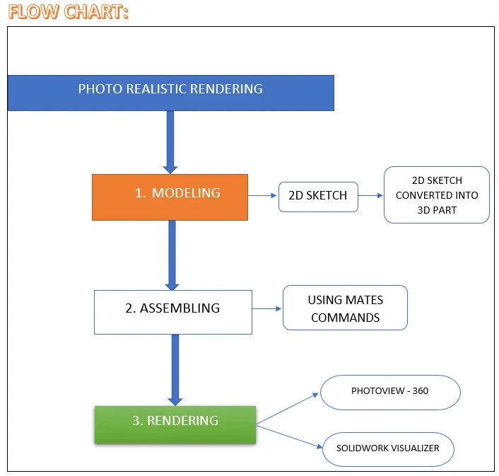
PART MODELING OF AMERICAN CHOPPER
Chopper Parts are Listed below:
- Transmission Belt
- Kickstand
- Front Fender
- Rear Fender
- Chain
- Oil Tank
- Pedal
- Front Wheel
- Rear Wheel
- Front Fork
- Chassis
- Engine
- Fuel Tank
PART MODELING:
The first step of part modeling is need to sketch the part in 2D by using the tools in Sketch Tab at solidworks software.
The second step of the part modeling is need to convert the 2D sketch into 3D part by using the tools in Features Tab at solidworks software.
2D SKETCH:
A 2D sketch is usually draw in any two Axis (x-axis,y-axis & z-axis).this is the 1st step of part modeling.
The sketch reflects its status as mentioned below,
Black - Fully Defined
Blue - Under Defined
Red - Over Defined.
The geometry relations also reflect in the sketchs which are parallel, vertical, horizontal, tangent, middle, etc….
SKETCH TOOLS USED:
In sketch tab there are lot of tools are available which are mentioned and explained below.
LINE:
This tool is used to Sketch a horizontal, vertical, or angled line.
RECTANGLE:
This tool is used to draw the rectangle as per user given dimensions.
POLYGON:
this tool helps to Sketch a polygon. Allows the user to input the number of sides on the polygon. Inserts pre-defined reference geometry to minimize sketch dimensions.
CIRCLE:
This tool helps to draw a circle by as per user inputs.
TANGENT ARC:
An incomplete circle defined by its tangency to the sketch entity.
SKETCH FILLET:
A tangent arc in between two sketch entities. Specify the radius by user.
SPLINE:
A two- or three-dimensional curve defined by a set of control points. Points within a spline can be added or deleted by user.
ELLIPSE:
This tool helps to Sketch a complete ellipse.
OFFSET ENTITIES:
This tool helps to Copy a sketch entity to a specified distance from the original entity. Must have a sketch entity already drawn and selected to use this tool.
3D DESIGN:
After complete the sketch, I create the 3D model by using Feature’s tab tools also I used applied features tools such as fillets, chamfers, or shells.
The Feature tab tools listed and explained below
EXTRUDE BOSS/BASE
The Extruded Boss is the most basic of all SOLIDWORKS features, and extrudes a sketch along a straight-line path to add material. As a sketched feature, it requires a sketch before use.
CUT-EXTRUDE
The Cut-Extrude tool is similar to an extrude feature, except that it removes material from the model instead of adding material.
FILLET
Fillet tool is used to making the round edges of part it may internal or external the most usage is to avoid sharp edges and make it smoothening.
REVOLVE BASE:
Revolves Base/Boss is a tool which is used to add material by revolving one or more profiles around a centreline.
SWEPT BASE/BOSS:
It is a tool which is used to creates a sweep base/boss in closed profile (section) along a path.
LOFT BASE/BOSS:
Loft base/boss is a tool which is used to create a loft in between two profiles along with guide path.
BOUNDARY SURFACE:
The boundary surface feature lets you create surfaces that can be tangent or curvature continuous in both directions (all sides of the surface). In most cases, this delivers a higher quality result than the loft tool.
SWEPT CUT:
The Swept cut tool is similar to an swept surface feature, except that it removes material from the model instead of adding material along with the sweep path.
REVOLVE CUT:
Revolves cut is a tool which is used to removing unwanted material by revolving one or more profiles around a centreline as per user given dimensions.
FILLET:
Fillet tool is used to creates a rounded internal or external face on the part. we can fillet all edges of a face, selected sets of faces, selected edges, or edge loops.
CHAMFER:
Chamfer tool is used to connect the two adjacent faces using an inclined line.
LINEAR PATTERN:
Linear pattern is a tool which is used to create ‘n’ number of selected body or part through user mentioned linear path.
CIRCULAR PATTERN:
Circular pattern is a tool which is used to create ‘n’ number of selected body or part through user mentioned circular path.
CURVE PATTERN:
Curve pattern is a tool which is used to create ‘n’ number of selected body or part through user mentioned curve path.
SHELL FEATURE:
The shell tool is helps to create hollows out a part and creates thin-walled features on the faces.
MIRROR FEATURE:
Mirror is a tool which is used to create a copy of one or more features, mirrored about a face or a plane.
DRAFT FEATURE:
Draft tools helps to create tapers faces using a specified angle to selected faces in the model.
DOME:
Dome tool is helps to create an elliptical or rounded shape of the part face with circular base.
SPLIT:
It is Use the Split Property Manager to divide parts into multiple bodies. You can use the Split Property Manager to save the new bodies when you split the part or use the Save Bodies Property Manager to save them after the split is complete.
COMBINE FEATURE:
In a multibody part, we can combine multiple solid bodies to create a single-bodied part or another multibody part.
We can add or subtract bodies, or keep material that is common to the selected bodies.
MOVE/COPY:
This tool is used to copy/move the 3D body from one place another places.
MIRROR:
Mirror tool is used to mirror the Solid body or feature by reference of the plane or feature.
EXTRUDE SURFACE:
This tool is used to create extruded surfaces from models that include 2D or 3D faces.
SWEPT SURFACE:
It is used to create a surface along with a path the curve is driven.
LOFT SURFACE:
Loft surface is a tool which is used to create a loft in between two profiles along with guide path.
You can cut a solid model by removing material with a surface or plane. With multibody parts, you can select which bodies to keep.
KNIT SURFACE:
The Knit Surface tool is used to combine two or more faces and surfaces into one.
Note the following about knit surfaces:
- Edges of the surfaces must be adjacent and not overlapping.
- Surfaces do not need to be on the same plane.
- Select the entire surface body, or select one or more adjacent surface bodies.
- Knit surfaces absorb the surface bodies you used to create them.
- Create a solid body when the knit surfaces form a closed volume, or leave as a surface body.
- Select Merge entities to merge faces with the same underlying geometry.
- Select Gap Control to view the gaps or modify the knitting tolerance
APPEARANCE:
An appearance defines the visual property of model including colours and textures. We can add appearances to faces, features, bodies, and the part itself. In an assembly, we can add appearances to components. It won’t affect the Dimensions of PART, BODY.
CMPONENTS MODELED:
1.TRANSMISSION BELT
The Below mentioned Features are used for this Model:
- SKETCH TOOLS
- OFFSET
- EXTRUDE BOSS/BASE
- FILLET
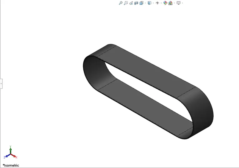
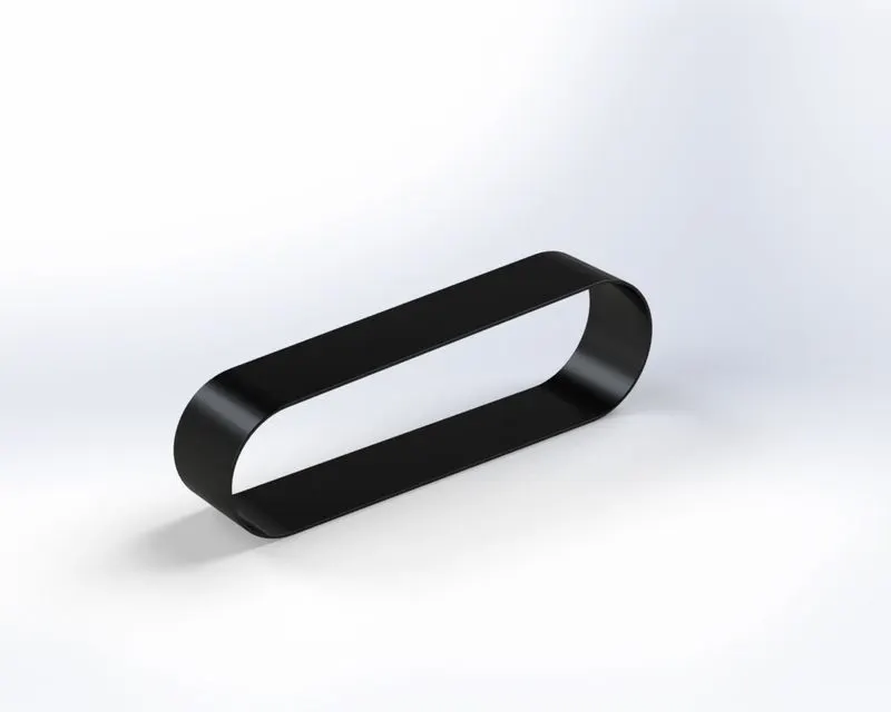
- Transmission Belt is used to transfer the Power from engine output shaft to Gear Box input shaft.
- Sketch has been drawn as per the adopted size of Engine’s pully in 2D by using the sketch tool of Line, curve & some relations.
- After it has been converted 3D model part by using the Extrude boss/base Tool.
Designed Model Part Image:
Rendered Model Part Image:
2.KICK STAND
The Below mentioned Features are used for this Model:
- SKETCH TOOL
- LOFT Base/Boss
- DOME
- ECTURDE CUT
- SPLIT
- EXTRUDE BOSS/BASE
- FILLET
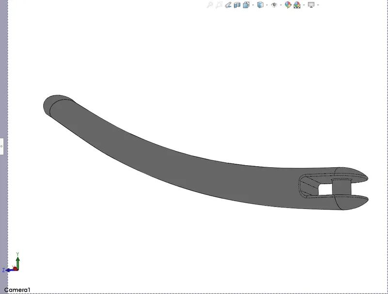
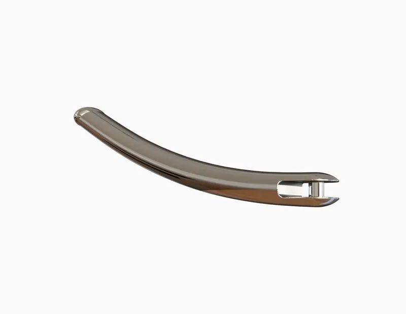
- Kickstand is used to stand the Vehicle on the floor for our specified angle.
- Stand sketch has been drawn as per our required dimensions by using the sketch tools like circle, angle line.
- After it has converted 2D into 3D part model some additional sketch also has been drawn on the part to create required shape by using the Lofted Base/Boss, Dome, Extrude Cut, Split, and fillet.
Designed Model Part Image:
Rendered Model Part Image:
FENDERS:
Here we have a two Fenders 1. Front fender, 2. Rear fender.
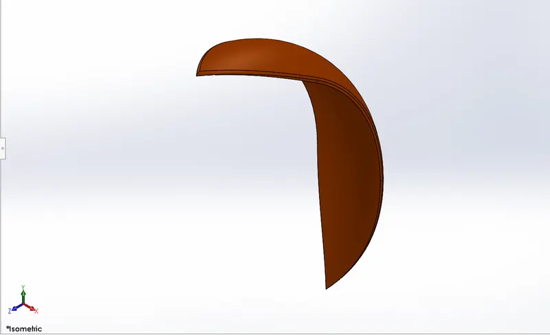
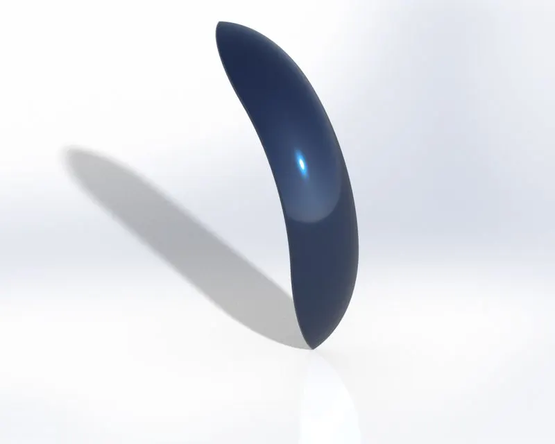
3.Front Fender:
The Below mentioned Features are used for this Model:
- SKETCH TOOLS
- REVOLVED BOSS/BASE
- SPLIT
- FILLET
- Front Fender is used to avoid the mud, sand, liquids and other spray throw into the air or on the engine by rotating force of tire.
- 2D sketch has been drawn as per the adopted size of tire to make a frame of tire.
- After it has converted 2D into 3D part model as per required dimensions.
- The pointed ends are created by Split tool. Then sharp edges are converted into round edges by using Fillet tool.
Designed Model Part Image:
Rendered Model Part Image:
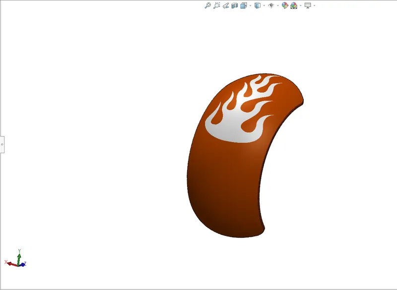
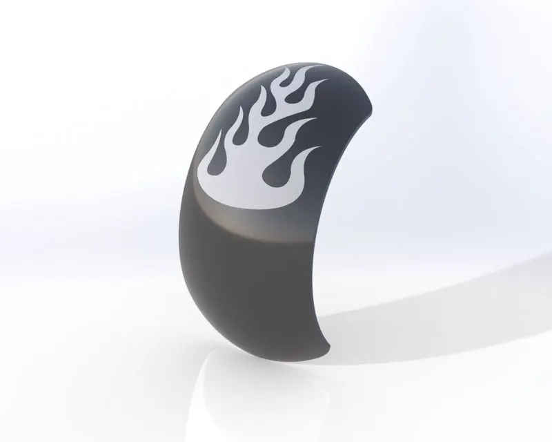
4.Rear Fender:
The Below mentioned Features are used for this Model:
- SKETCH TOOLS
- REVOLVED BOSS/BASE
- SPLIT
- FILLET
- SHELL
- It is used to avoid the mud, sand, liquids and other spray things throw into the air or on the engine by rotating force of tire.
- 2D sketch has been drawn as per the adopted size of tire to make a frame of tire.
- After it has converted 2D into 3D part model as per required dimensions.
- It is Shorter and thicker than front fender. It has round end as per the design idea.
Designed Model Part Image:
Rendered Model Part Image:
5.CHAIN:
The Below mentioned Features are used for this Model:
- SKETCH TOOLS
- EXTRUDE BOSS/BASE
- LINEAR PATTERN
- CURVE PATTERN
- FILLET
- MIRROR
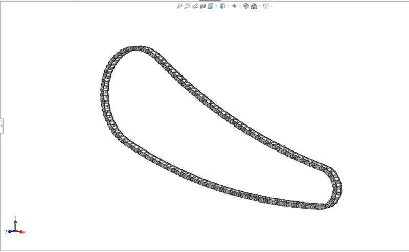
- Chain is used to transmitted the power from Gear box output shaft to Rear wheel sprocket.
- 2D sketch has been drawn for outer plate & Inner plate blocks of chain.
- After it has converted 2D into 3D part model as per required dimensions.
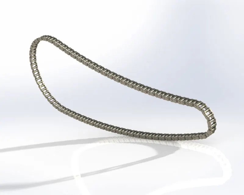
- Here total 390 solid bodies are used to create required dimension part Which are 130 outer plate, 130 inner plate and 130 pins.
- We used linear pattern command for n number of bodies created on the linear area of chain and we used curve pattern command for n number of bodies created on curved area of chain.
- The above-mentioned bodies are should keep separate body because it has to rotate along with curve and around sprocket. if we merge and make it as single body, it couldn’t work.
Designed Model Part Image:
Rendered Model Part Image:
6.OIL TANK:
The Below mentioned Features are used for this Model:
- SKETCH TOOLS
- EXTRUDE BOSS/BASE
- COMBINE
- SHELL
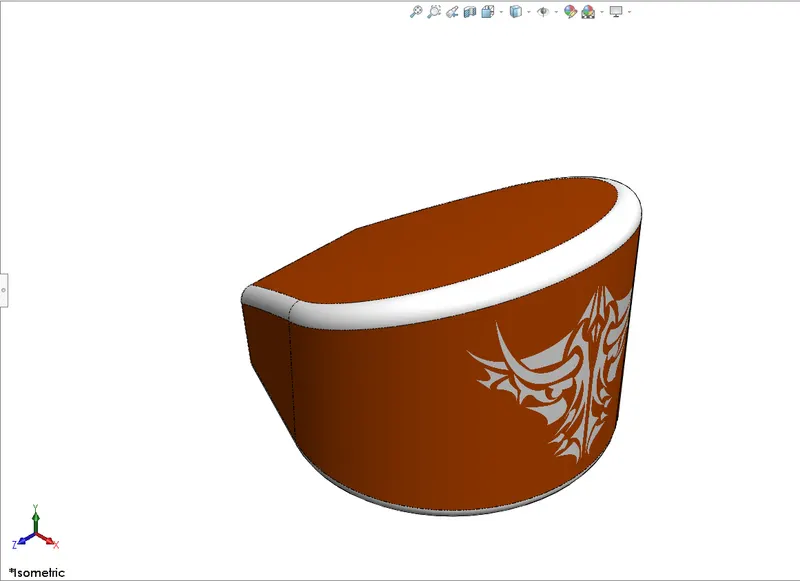
- Oil Tank is used to supply the oil to the engine crank shaft, Piston & Engine Cylinder to reduce the friction. It is placed on the engine block which is also made hallow inside.
- 2D sketch has been drawn for adopted size of oil tank.
- After it has converted 2D into 3D part model as per required dimensions.
- Shell tool is used to make the tank to be hollow.
Designed Model Part Image:
Rendered Model Part Image:
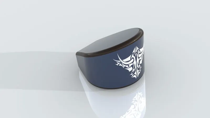
7.PEDAL
The Below mentioned Features are used for this Model:
- EXTRUDE BOSS/BASE
- REVOLVE
- DOME
- CHAMFER
- FILLET
- LINEAR PATTERN
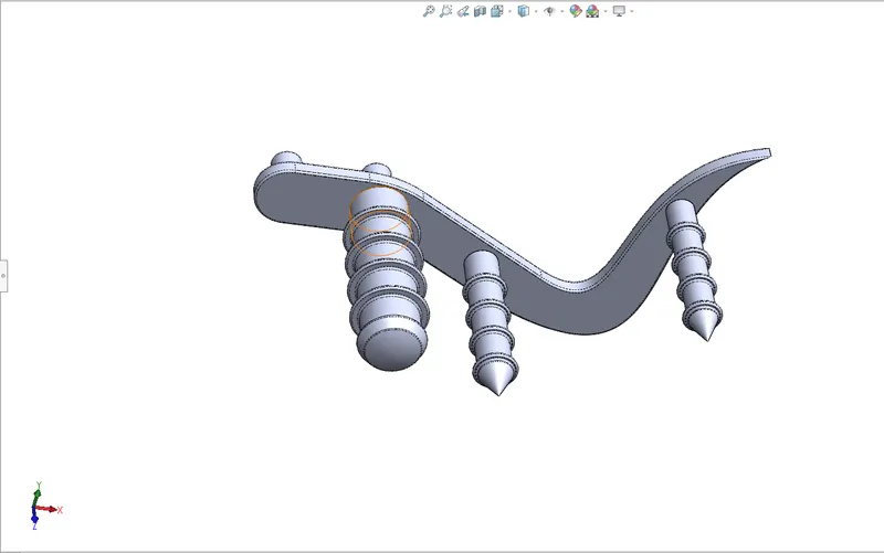
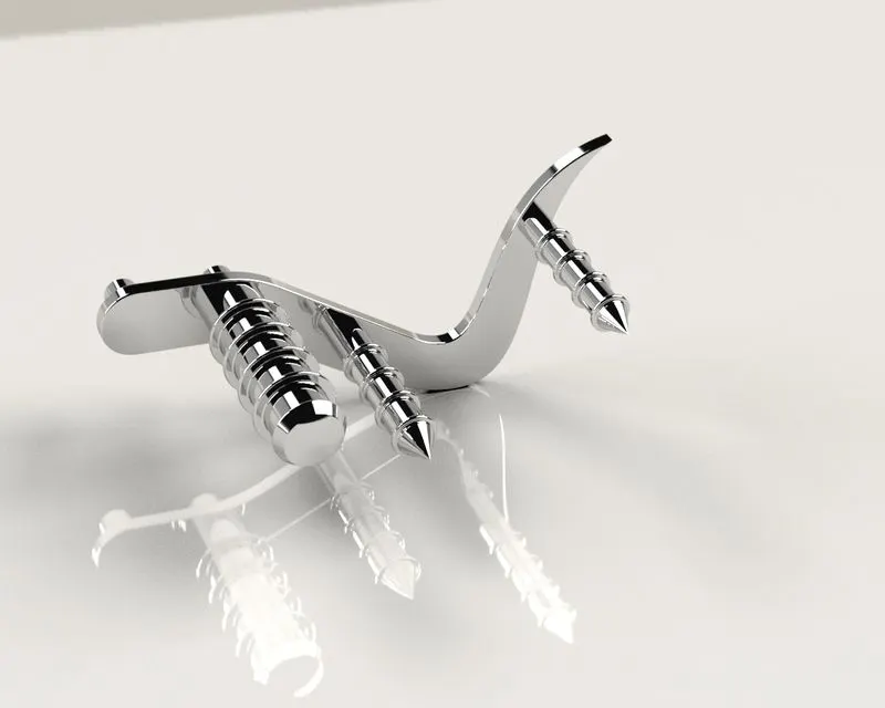
- Pedal is used as a leaver controller of brake and gear by the foot.
- 2D sketch has been drawn for adopted size to the Chassis.
- After it has converted 2D into 3D part model as per required dimensions. Here right-hand side pedal is modelled, left hand side pedal is mirrored.
Designed Model Part Image:
Rendered Model Part Image:
8.FRONT WHEEL:
The Below mentioned Features are used for this Model:
- SKETCH TOOLS
- REVOLVED BOSS/BASE
- EXTRUDE BOSS/BASE
- REVOLVE CUT
- CIRCULAR PATTERN
- FILLET
- CHAMFER
- COMBINE
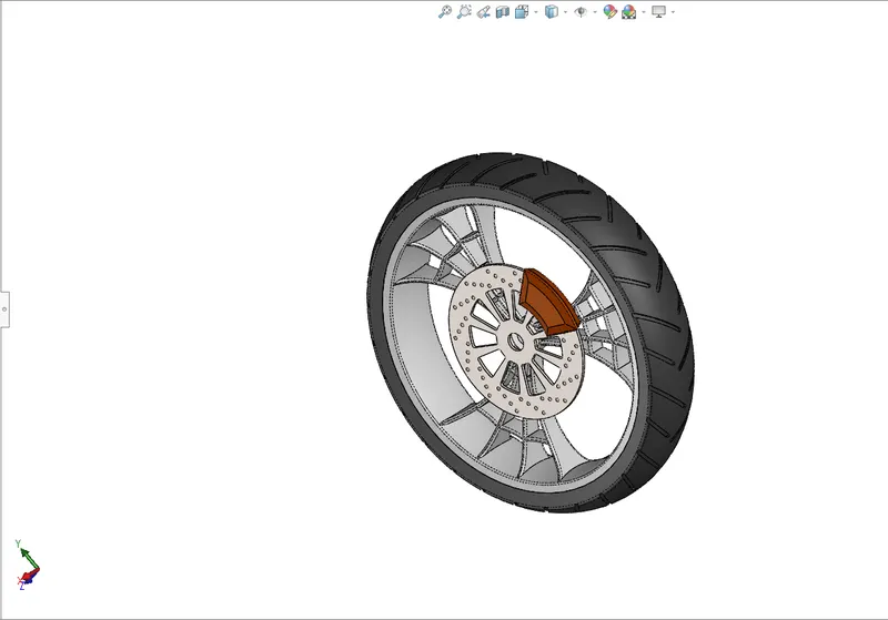
- Front Wheel is thinner than the Rear wheel. It contains many parts like Rim, Rotor, Calliper, Tire.
- 2D sketch has been drawn for adopted size of front wheel.
- After it has converted 2D into 3D part model as per required dimensions. Here we design the wheel alloy is like spider web.
Designed Model Part Image:
Rendered Model Part Image:
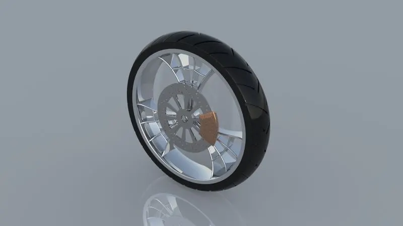
9.REAR WHEEL:
The Below mentioned Features are used for this Model:
- SKETCH TOOLS
- REVOLVED BOSS/BASE
- EXTRUDE BOSS/BASE
- REVOLVE CUT
- CIRCULAR PATTERN
- FILLET
- CHAMFER
- COMBINE
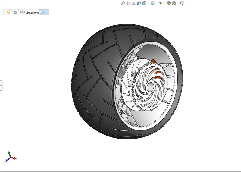
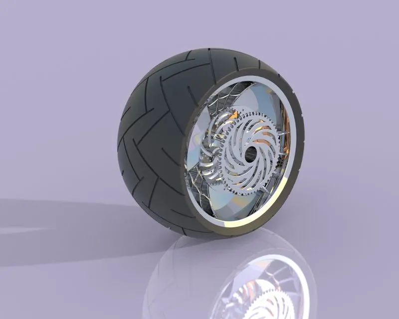
- Rear Wheel design is similar to the Front Wheel design additionally one part is added.
- It contains 5 solid bodies which are Rim, Rotor, Calliper, Tire and Sprocket.
- The sprocket teeth are counted design.
Designed Model Part Image:
Rendered Model Part Image:
10.FRONT FORK:
The Below mentioned Features are used for this Model:
- SKETCH TOOLS
- REVOLVED BOSS/BASE
- EXTRUDE BOSS/BASE
- REVOLVE CUT
- FILLET
- CHAMFER
- COMBINE
- PROJECTED CURVE
- SWEPT BOSS/BASE
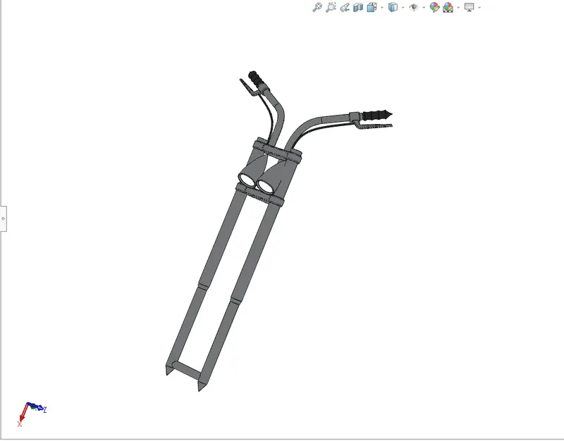
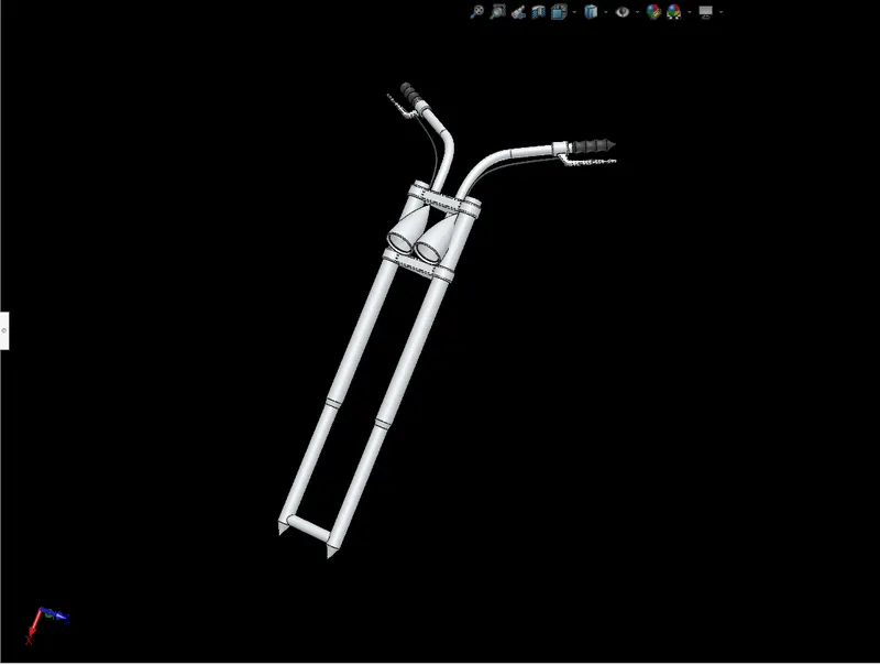
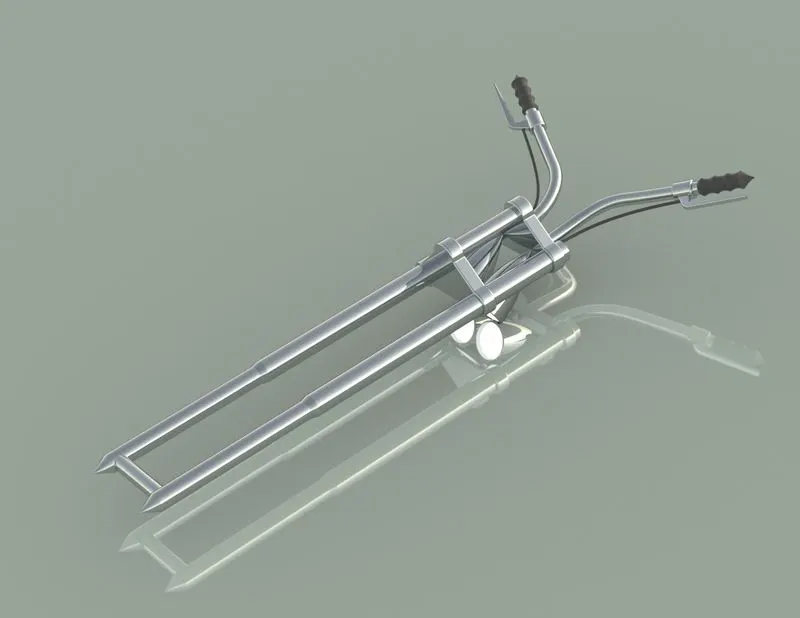
- Front Fork is used to direct the vehicle while running it has many hand control devices like front brake, head light, indicator, clutch, self-starter switch and etc also it gives the space to mounting the many parts like front wheel, head lights and etc….
- 2D sketch has been drawn for adopted size to the Chassis.
- After it has converted 2D into 3D part model as per required dimensions. here we create the many new planes to achieve the special designed front fork.
Designed Model Part Image:
Rendered Model Part Image:
11.CHASSIS:
The Below mentioned Features are used for this Model:
- SKETCH TOOLS
- EXTRUDE BOSS/BASE
- SWEPT BOSS/BASE
- PROJECTED CURVE
- SPLIT
- FILLET
- CHAMFER
- COMBINE
- MIRROR
- DOME
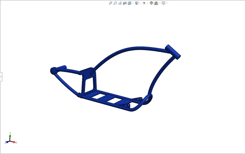
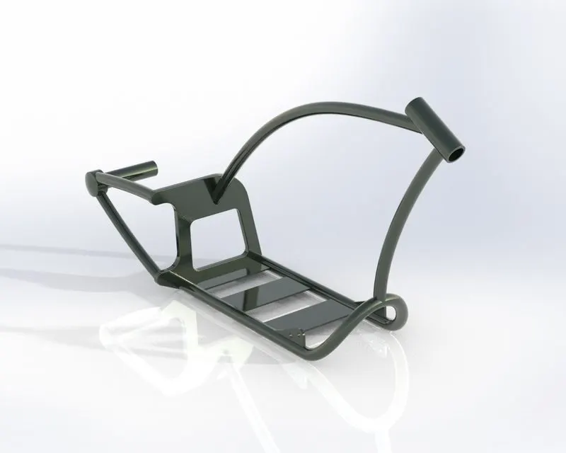
- The chassis is the Frame of the chopper it bears the most of the weight. In chassis designing is all parts should be mounted with it and also it gives unique look.
- 2D sketch has been drawn for adopted size of initial design idea.
- After it has converted 2D into 3D part model as per required dimensions. Here we mostly used command is Swept Base/Boss tool.
Designed Model Part Image:
Rendered Model Part Image:
12.ENGINE:
The Below mentioned Features are used for this Model:
- SKETCH TOOLS
- EXTRUDE BOSS/BASE
- FILLET
- REVOLVE
- DOME
- CIRCULAR PATTERN
- CURVE
- COMPOSITE CURVE
- FILLET CHAMFER
- SWEPT BASE/BOSS
- L PATTERN
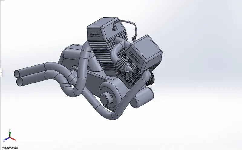
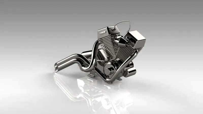
- We know that Engine is the heart part of bike it powers the bike. The V type engine with 2 Exhaust pipe designed for chopper.
- It contains inlet & outlet volves, spark plug, cooling fins, power transmission unit and etc…
- 2D sketch has been drawn for adopted size of initial design idea.
- After it has converted 2D into 3D part model as per required dimensions. Here we mostly used command is Composite tool.
Designed Model Part Image:
Rendered Model Part Image:
13.GAS TANK:
The Below mentioned Features are used for this Model:
- SKETCH TOOLS
- SWEPT SURFACE
- SURFACE TRIM
- SURFACE LOFT
- CURVE
- BOUNDARY SURFACE
- SURFACE KNIT
- FILLET SHELL
- SWEPT CUT
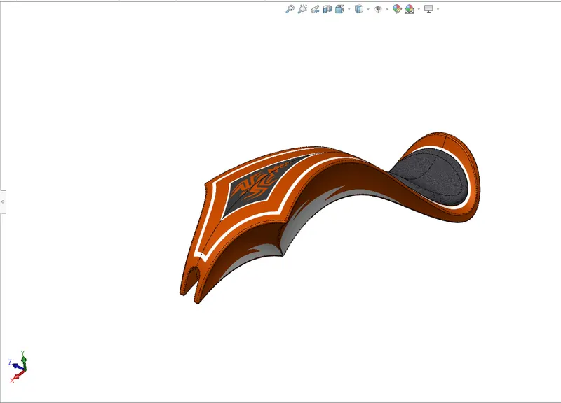
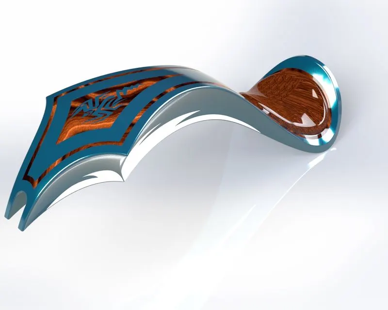
- The fuel tank for this Chopper is designed as per info sketch.
- we made hollow inside the gas tank to store the Fuel. In this part design we used Surface feature tab.
- 2D sketch has been drawn for adopted size of initial design idea.
- After it has converted 2D into 3D part model as per required dimensions. the bottom of the fuel tank is designed as per the Chassis’ dimension for mounting purpose.
Designed Model Part Image:
Rendered Model Part Image:
ASSEMBLING
Assembly is most often referred to components together in an assembly line, but more specifically, it refers to creating a complete product that performs an intended function.
ASSEMBLY APPROCHES IN SOLIDWORKS
- TOP – DOWN APPROCH
- BOTTOM – UP APPROCH
All parts are inserted in assembly file those are merge and join together by using mates’ command.
MATES:
Mates create geometric relationships between assembly components. As you add mates, you define the allowable directions of linear or rotational motion of the components. You can move a component within its degrees of freedom, visualizing the assembly's behaviour.
The below mentioned few mates commands are used for American Chopper Assembly:
- Angle Mate
- Reference Entity for Angle Mates
- Coincident Mate
- Concentric Mate
- Distance Mate
- Lock Mate
- Parallel and Perpendicular Mates
- Tangent Mate
NOTE:
If we change the component’s dimensions or appearance immediately it will be reflected in the assembly i.e., the rebuild happen automatically or it will ask the user to rebuild it.
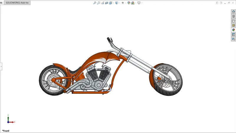
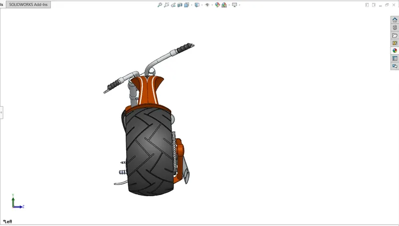
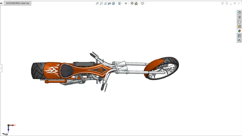
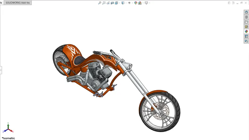
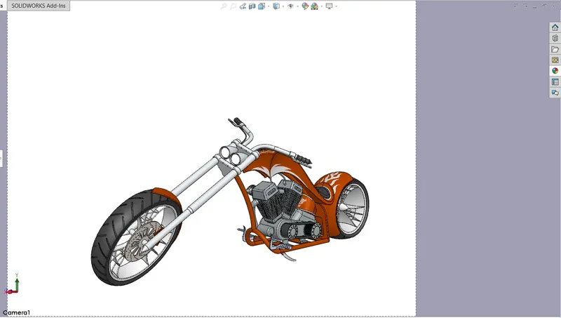
Assembled View of American Chopper:
Front view of the Assembled American Chopper
Side view of the Assembled American Chopper
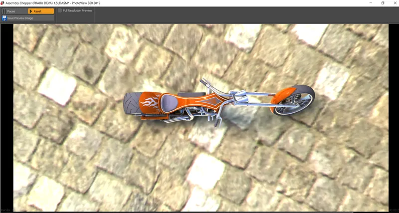
Top view of the Assembled American Chopper
Isometric view of the Assembled American Chopper
Camera view of the Assembled American Chopper
RENDERING:
The term rendering is analogous to the concept of an artist’s impression of scene.
The rendering of 3D CAD model in solidwork can be done by using the below software:
- Photoview -360
- Solidwork visualize
PHOTOVIEW-360
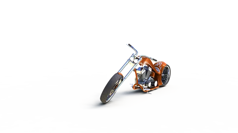
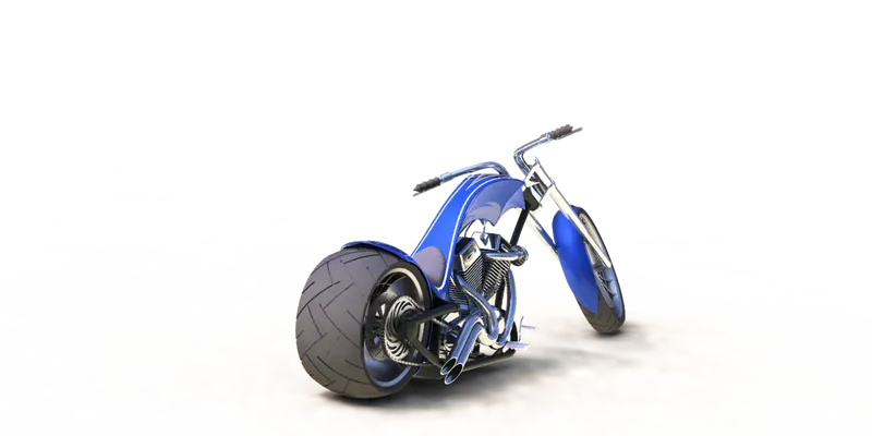
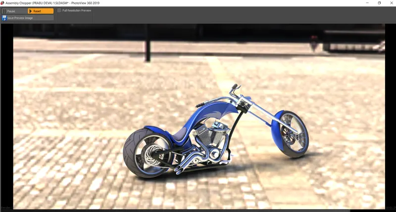
PhotoView 360 is a SOLIDWORKS add-in that produces photo-realistic renderings of SOLIDWORKS models. The rendered image incorporates the appearances, lighting, scene, and decals included with the model. PhotoView 360 is available with SOLIDWORKS Professional or SOLIDWORKS Premium.
Rendering images of American Chooper done by Photoview-360:
SOLIDWORK VISUALIZE
SOLIDWORKS Visualize (formerly known as Bunkspeed) provides a suite of standalone software tools that combine industry-leading rendering capabilities with visual design-oriented features and workflows, allowing easy and fast creation of visual content that communicates a design’s vision, passion, and emotion.
Rendering Images of American Chopper done by Solidwork Visualize:
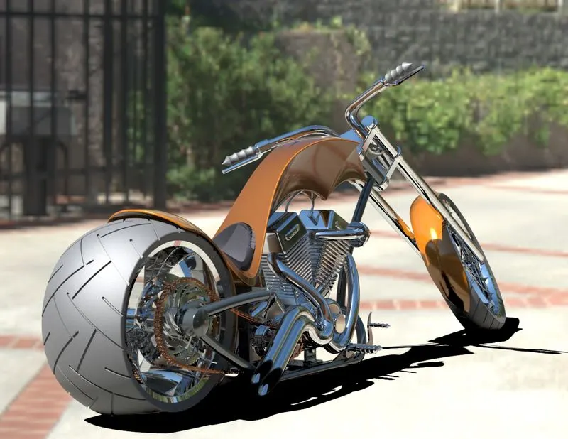
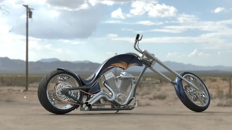
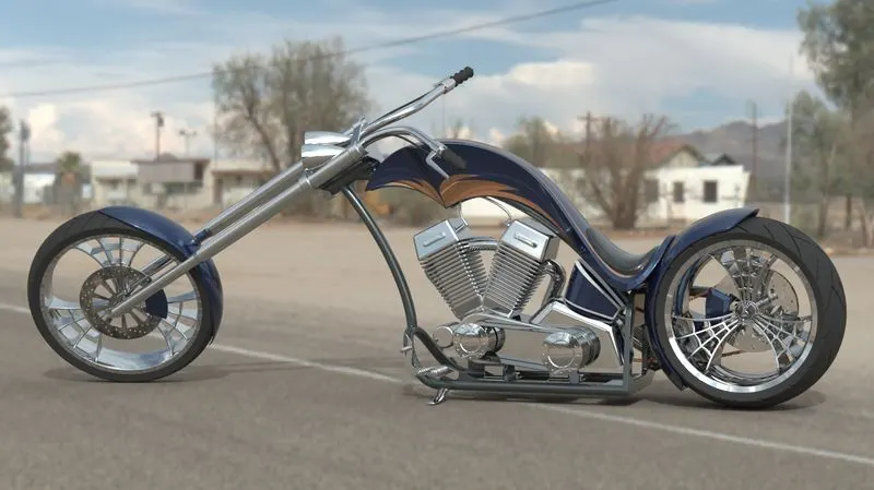
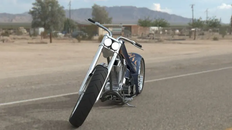

Finally I have completed the Rendering of American Chopper by using the Photoview - 360 and Solidwork Visualize softwares.
CONCLUSION
Happily, I have concluded that, I have successfully learnt the way of using the solid and surface modeling Features of solidwork software and also i have learnt to create Rendering images of 2D & 3D modeling by using the Photoview-360 & Solidwork Visualize softwares.