Photo Realistic Rendering
Complete solidworks course-Assembly of Chopper Model.
Objective
The main objective of the course is to learn darwing, designing parts , assemblying them together and rendering the chopper in the solidworks visualizations
Introduction
The main aim of the course is to design a chopper , for which we are required to first design individual parts and combine them to make a single assembly
Design Methodology
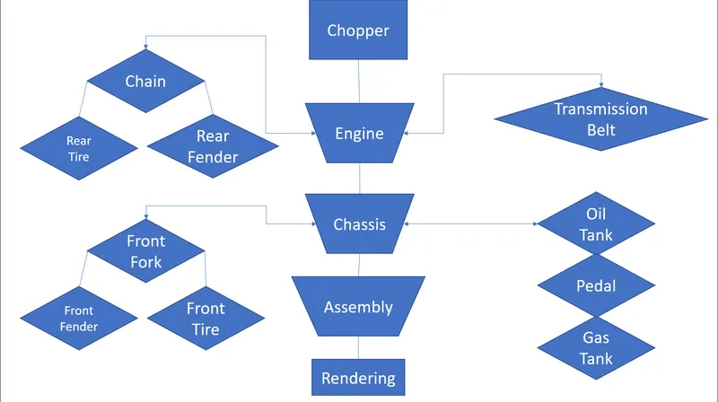
Description
-Extrude
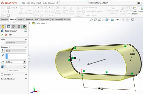
The extrude command is a commonly used command , The main function of the command is
to elongate any sketch into solid three dimensional piece, which is perpendicular to the sketch plane.
The main requirement to use the command is to main a closed sketch as shown in the figure.
-Cut Extrude
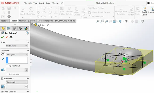
The main function of the cut extrude command is just opposite to that of the extrude command.
i.e, the function removes the required extrusion which lies in the path perpendicular to the sketch plane.
Here also , the sketch should be closed.
-Loft Command
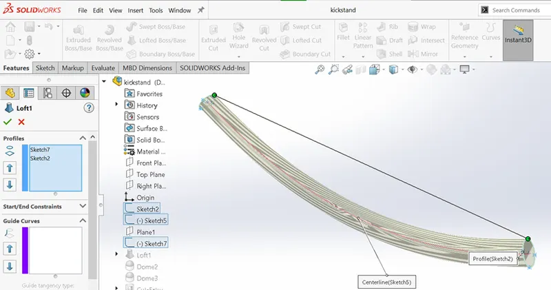
Loft command is used to connect 2 closed sketches to make a surface or a solid in three dimension.
There are many customizations to join the two sketches as per the requirement.
-Circular Pattern
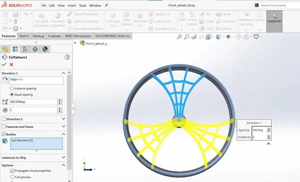
Circular pattern is helpful in creating circular patterns of any body , as shown in the figure we require
to select a body and the circular path , that is to be followed. The above image shows designing of rim .
-Linear Pattern
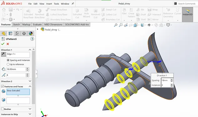
Linear pattern is same as circular pattern , the only difference is the instead of using a circular reference ,
a linear reference is used . The above image shown the making of grip on the paddle through linear pattern
-Revolve
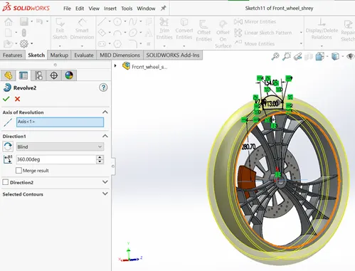
The main function of the revolve command is to sweep the object in circle about a reference axis to make a 3d surface or a solid .
The image above shows how the tire is made using the revolved boss command.
-Fillets
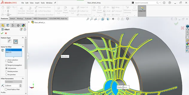
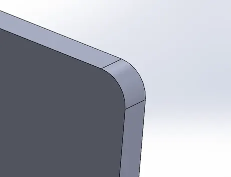
The fillets are used to curve out sharp edges , externally or internally . The fillet menu lets us customize the radius of the curve ,
it can even provide options to create different types of fillets.
-Chamfer
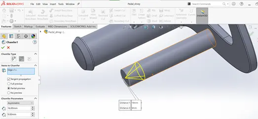
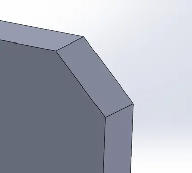
The chamfer is also used to remove sharp edges, the only difference between
Fillet and chamfer is that fillet produces curves while chamfer creates sloped edges.
-Shell
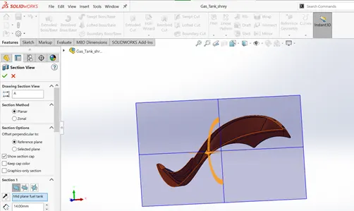
The main purpose of the shell command is to produce shell , i.e, converting solid objects to hollow.
As shown in the figure we can see that hollow gas tank in section view.
-Surface Loft
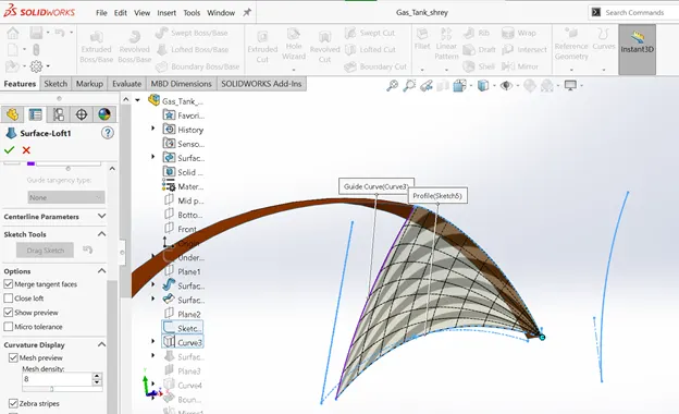
Surface loft is used to create surface in 3 dimension, we need to select profiles and a guide curve to create a surface
-Mirror
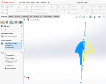
Mirror command is a handy tool to make symmetric bodies , the body and the mirror
plane is to be selected. The above image shows the making of gas tank by mirroring it symmetric .
-Combine
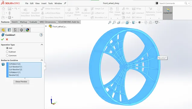
The main purpose of the combine command is that it helps in combining two or many bodies
to a single combined body. The image shows how the rim is designed and combined.
-Reference Plane
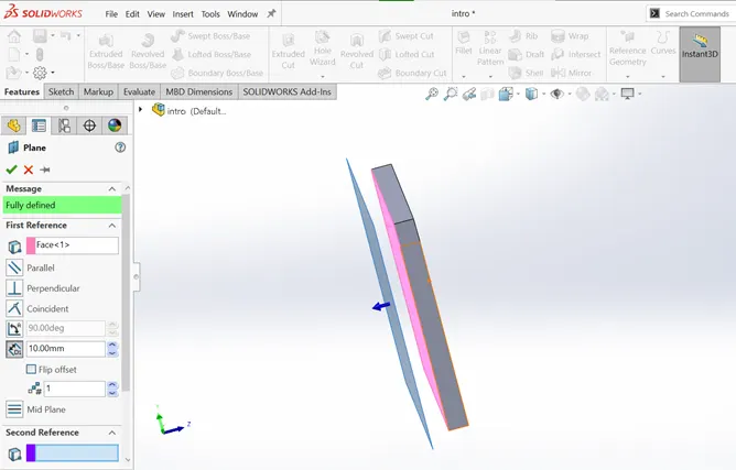
Reference planes are used to create sketch on a plane as per requirements ,
many options are provided to align the plane to the mentioned position .
-Projection Curve
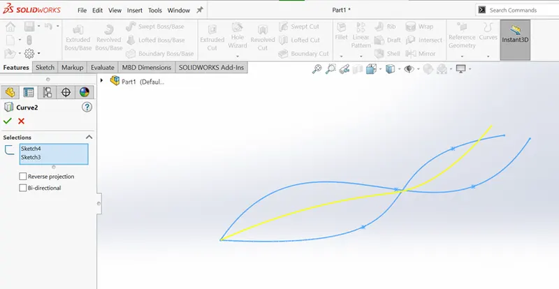
Projected curve is used to create a three dimensional curve using two 2 dimensional sketches in different planes.
-Split
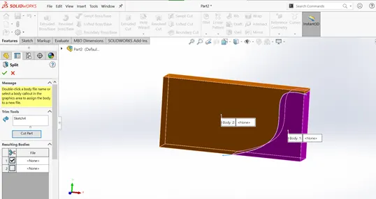
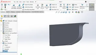
Split tool is used to split bodies between a sketch , it can be decided which sid of the part is to be cut ,
you can even consume the cut body as shown in the second figure
-Sweep
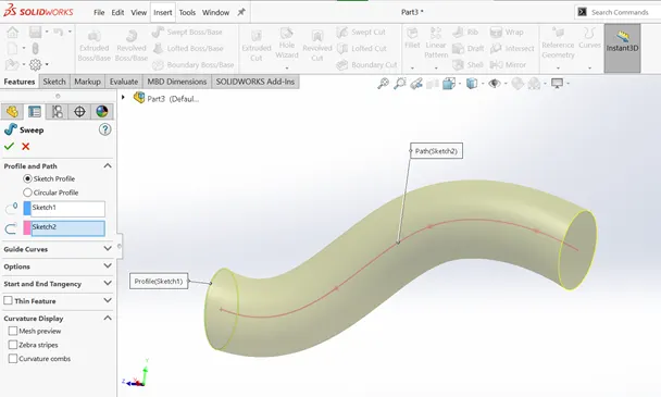
Sweep function helps in producing 3 dimensional surface or solid with the help of the
sketch to be swept and the path as shown.
(1)Transmission Belt
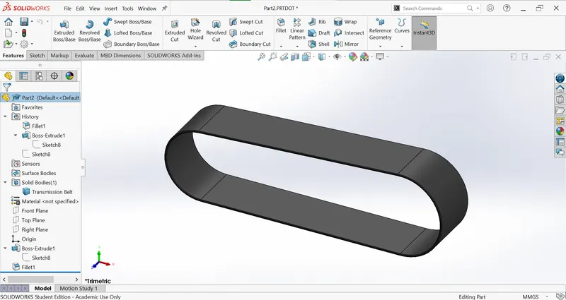
In the above part , basic functions are used , such as
Sketch (Drawing a closed sketch) and we used off set entities (To off set the sketch) then we used the extrude command to extrude the sketch as to make the desired shape and then we gave the appearance
(2)Kickstand
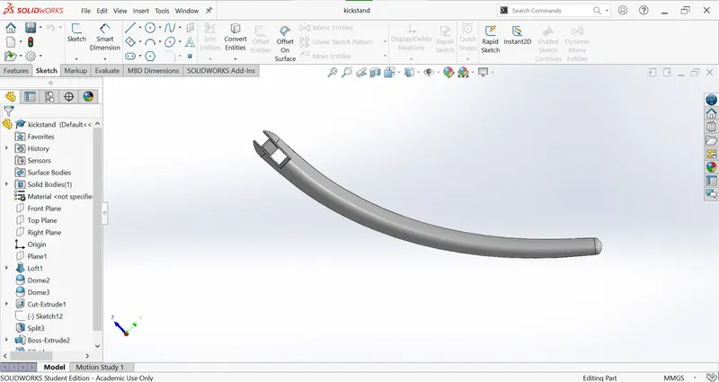
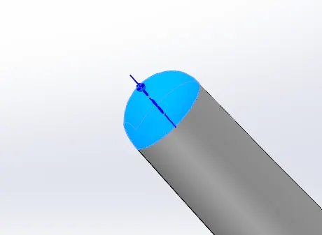
The new fuction used here is "Spline", to give the required curved shape of the kickstand . Then we used the loft command, the main purpose of the loft command is that it allows to extrude a sketch on a required path, then we used the dome command from the function tab to give a finishing touch to the ends of the kickstand then we used the cut extrude command to remove the unwanted part. Then we used the fillet command to soften out the sharp edges.
(3.)Front Fender
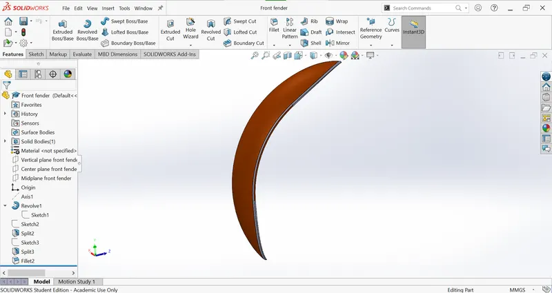
First we performed the sketch, the we renamed the planes as per convenience, then we used the revolve command to extrude with respect to the axis of rotation. Now we make a new sketch and performed the split command, the main purpose of the command is that it allow us to choose and cut body from the main part. Then we used the fillit command on the edges and at last we choose the appearance and painted it in siana
(4.)Rear Fender
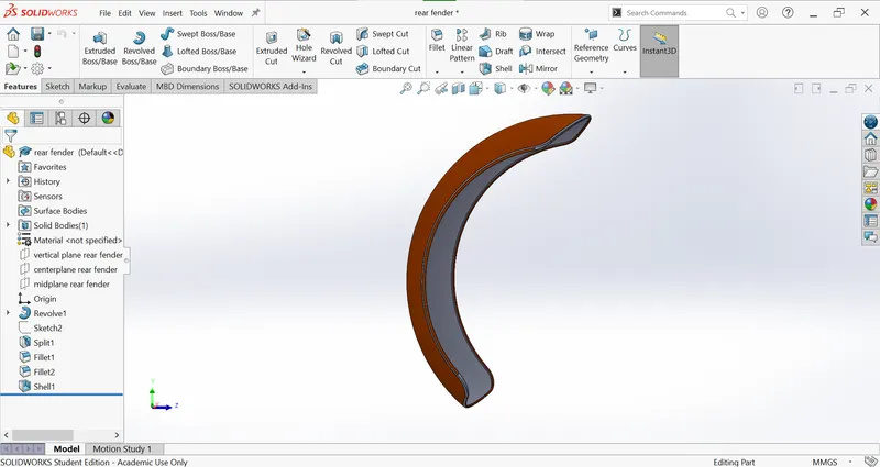
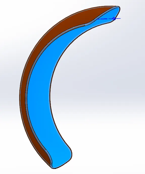
All the functions are similar to that used in making the front fender , though here we have used shell command which helps in creating a shell in the inner part
(5.)Pedal
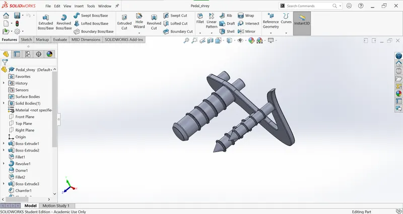
In this part we have performed different functions such as sketch, extrude cylindrical shapes , add fillet , the new feature used in the part to create grip is linear pattern , linear pattern helps in creating a pattern in linear direction with a bunch of customizations such as the number of patterns , etc.
(6.)Chain
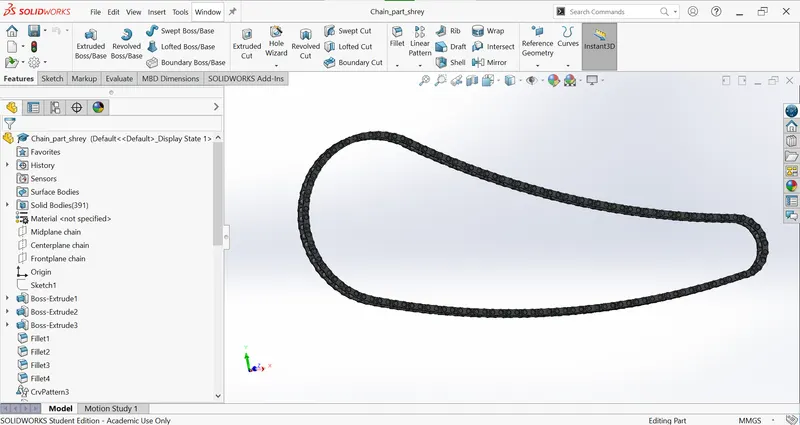
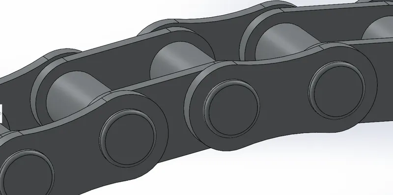
The chain part was one of the most difficult part to make , first we created two chain links as shown ,which would help in connecting the chain, then we save these bodies as chainlink so that as per requirements we can manually adjust and produce the chainlinks as per the requirement, then we created a sketch which gives direction to the linear pattern for the chainlink. Now the problem was that , if i selected the whole path for the linear pattern , after some time it would get distorted , so i performed linear pattern four times and manually put some chainlinks in place if required. Then we performed the mirron function about mid plane to complete the chain .
(7.)Oil tank
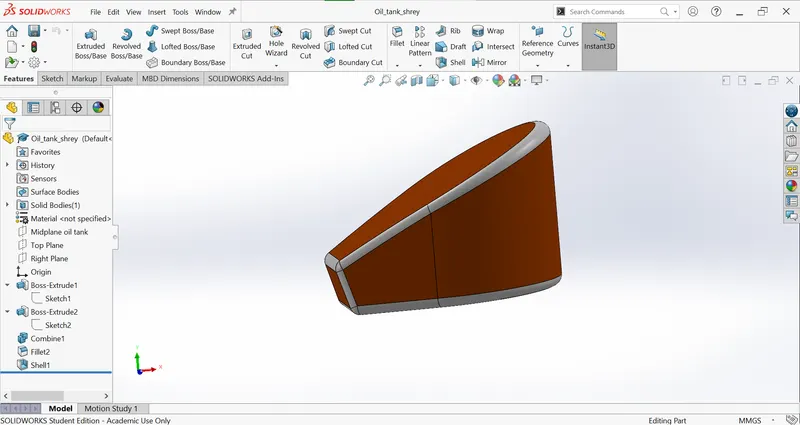
In this part we sketch and extrude 2 body and we use the combine command to use the intersection of the bodies which result in the required shape , then we make the use of shell command and make the solid body hollow and at the end we give the appearence to the part as shown.
(8.)Front wheel
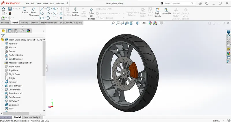
First We made the outer part of the rim with the help to revolve cammand
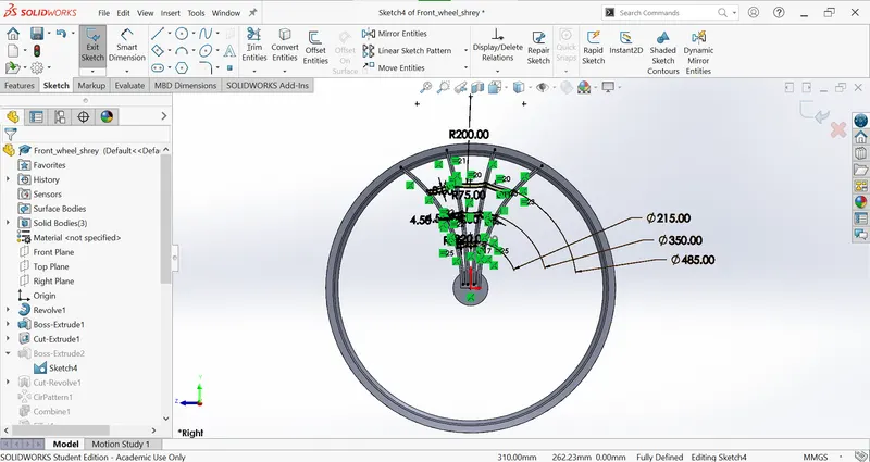
As shown in the figure , the design of the wheel is created and with the help of circular pattern commant it is distributed as per design.Then the disk plate and the calipers are made from
sketching, extruding and applying circular pattern to the holes
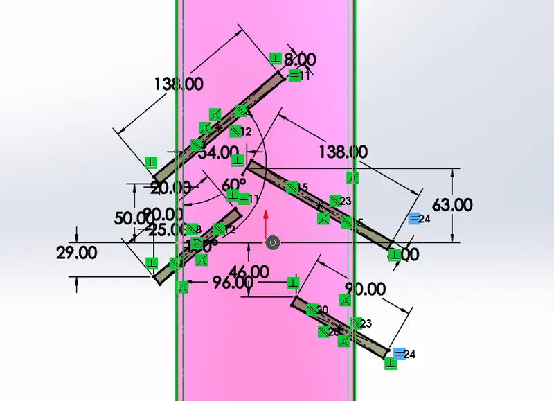
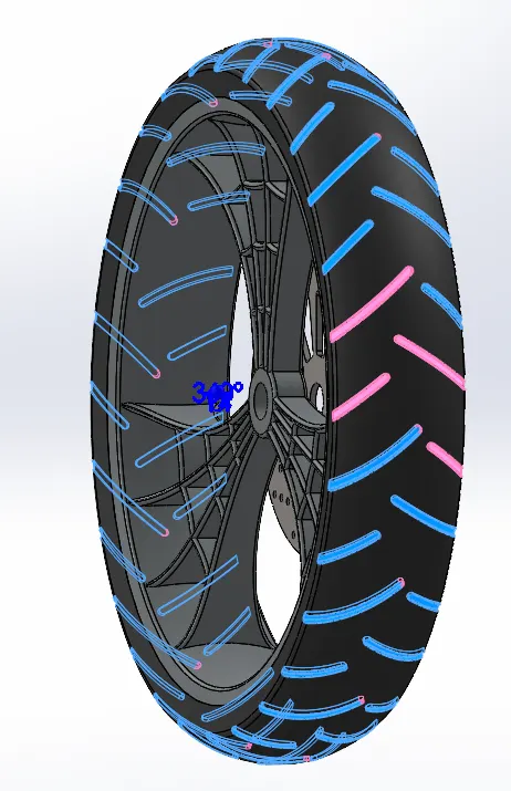
At the end the tire pattern is sketched and cut extruded and made it a circular pattern.
(9.)Rear wheel
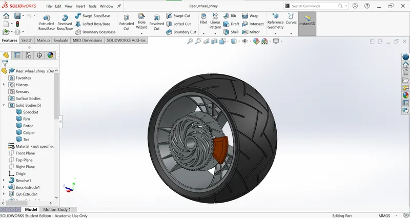
The only difference is that the rear tire has got a sprocket , which is made to hold the chain and is made of cut extrude and applying circular pattern.
(10.)Engine
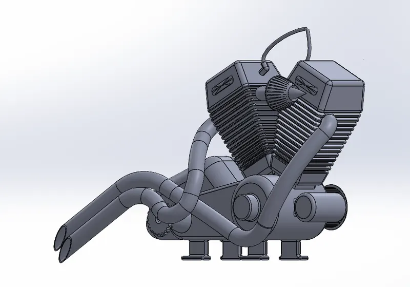
Engine is complex part, it uses many commands to create the part.The main work of the engine is to generate power, required by the chopper.
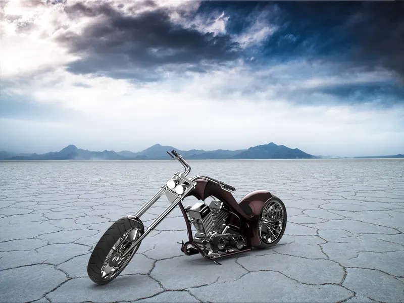
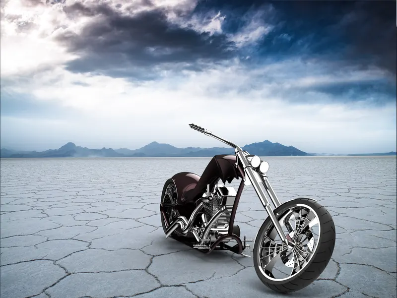
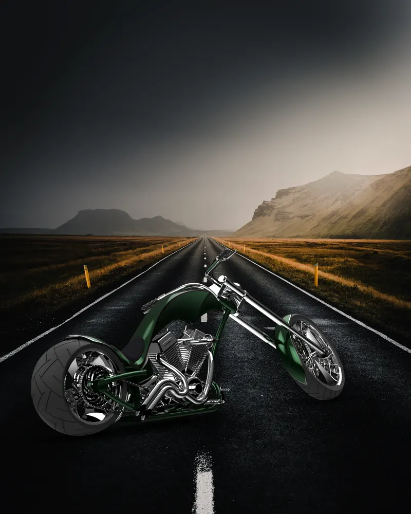
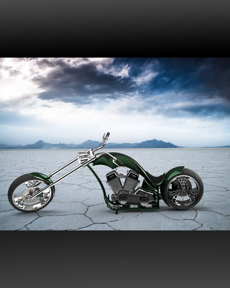
Rendered Images
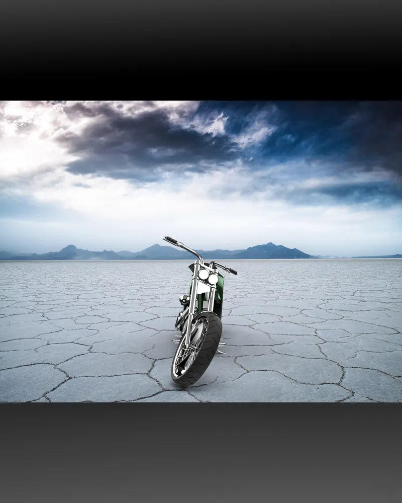
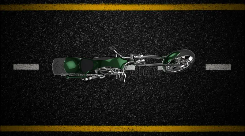
Conclusion
To Summarize , we got to know many tools and functions of solidworks, how they work and how to impliment, while making the chopper we come to know how solidworks is used in creating sketches, converting them to three dimensional parts , we come to know how the the chopper is assembled . Then we come to know about solidworks visualise, how rendering is done, how to apply customizations .