Photo Realistic Rendering
To Model, Design, assembly, and Rendering of American chopper Using Solidworks and Photoview 360
- Objective -The Objective of this project report is to Design a 3D Model of American Chopper in Solid works and to Learn Solid Modelling.
- Introduction - The American Chopper is a type of custom motorcycle. The chopper is perhaps the most extreme of all custom styles, often using radically modified steering angles and lengthened forks for a stretched-out appearance.
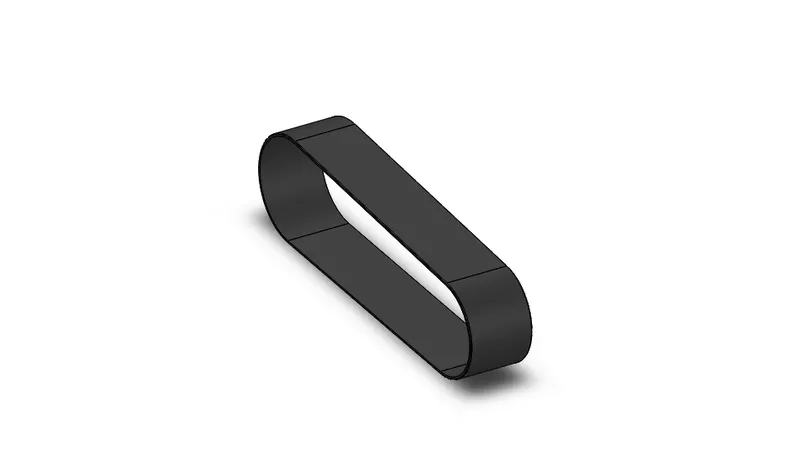
- Design Methodology- TRANSMISSION BELT- To Model Transmission belt, I draw 2d sketch profile of belt on front plane using smart inbuilt technology of solid works & offset it 3.5mm outer, now I Extrude it by 88mm depth and apply 1mm radius fillets to all Edges.
- Features
- Boss Extrude-An Extruded Boss/Base feature will allow to take a 2d sketch and add thickness to it in the third dimension.
- Fillet-A fillet is a rounding of an Interior or Exterior corner of a part design.
- Offset- Offset one or more sketch Entities, selected model edges, or model faces by a specified distance.
KICKSTAND
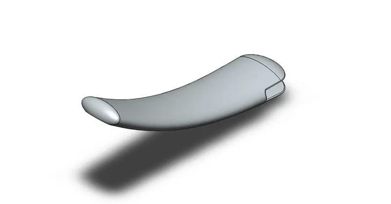
To Model kickstand first I make Solid profile of kickstand, then I apply dome of 13mm & 5mm to the Body, Now I cut the front part of body Using Cut Extrude Feature using through all. Using Split feature, I make flat surface on back of body. A solid boss of 8mm thickness is created on front part of Body, Fillet of 0.5mm radius is applied on external edges, and 2mm radius on internal edges is applied.
Feature-
- Loft-This feature allows us to generate complex geometry in a single feature.
- Dome-Dome feature is used to give 3d arc like shape to the Plane Surface.
- Cut Extrude-It is used to Remove Material by projecting a sketched section Normal to the sketching plane.
- Split-It is used to cut the material by projecting line.
- OIL TANK
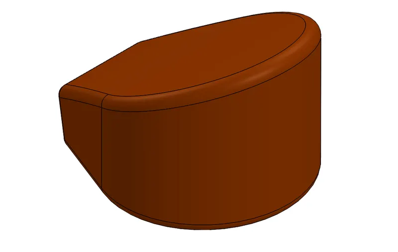
To model oil tank First I draw 2d sketch on top plane & extrude it 170mm depth, again I draw sketch and extrude using through all feature. Next I apply combine feature and 10mm radius fillet & 3mm shell.
Features
- Boss Extrude.
- Combine.
- Shell
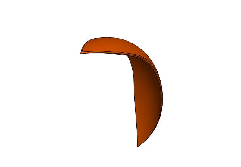
Front Fender-Fender of motorcycle prevent sand, mud, rocks, liquids, and other road spray from being thrown into the air by the rotating tire.First I rename the planes, front plane as Vertical plane front fender, Top plane as Center plane front fender, & Right plane as Mid plane front fender.
To design fender, I draw 2d sketch profile for revolve then I draw another sketch on top of fender for split 1, Now another sketch is drawn on bottom of fender for split 2, Now complete the sketch applying 6mm radius fillet to all edges.
- Features
- Revolve-Revolve feature is used to revolve a 2d sketch along an axis or centerline
- Split-The split line tool is used to project an entity(sketch, solid, surface, face, plane, or surface) spline.
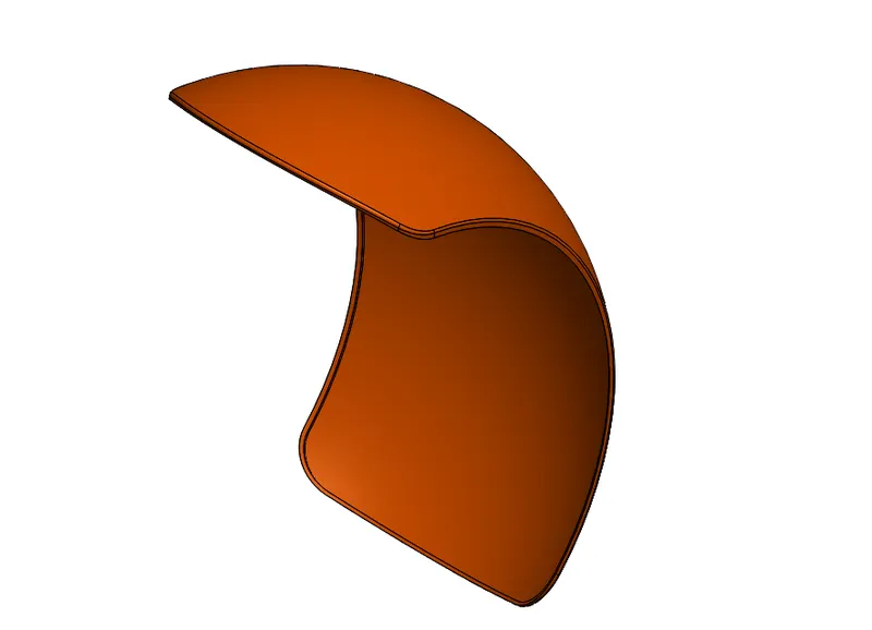
- Rear Fender-To Model Rear Fender, I make 2d sketch profile for Revolve, then I make sketch on center plane Rear fender for Split, 45mm radius fillet applied to all 4 Corner edges, 4mm radius fillet is applied to all External edges, Shell of 4mm thickness is applied.
- Features
- Revolve-Revolve feature is used to revolve a 2d sketch along an axis or centerline.
- Shell-Shell tool hollows out a part, leaves open the faces you select, and creates thin-walled features on remaining faces.
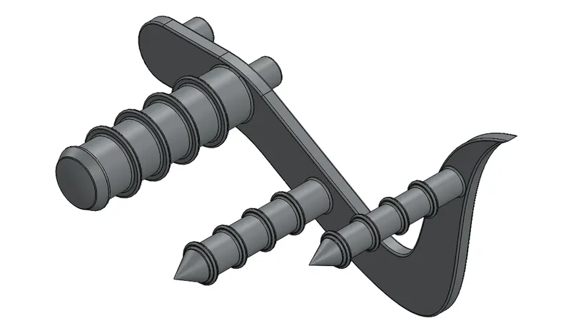
- Pedal-To Model pedal, I draw 2d sketch profile for two boss Extrude, First is 8mm thick and Second is 20mm thick, then I apply 1mm radius fillet and draw another 2d sketch for Revolve, 3mm dome and 1mm radius fillet to the edges is applied. Again boss extrude of 100mm depth is Applied, 1st chamfer with distance d1-16mm, d2- 9mm is applied and 2nd Chamfer with D1-16mm, D2-7.5mm is Applied.
- Features
- Boss Extrude- An Extruded Boss/Base feature will allow to take a 2d sketch and add thickness to it in the third dimension
- Chamfer-Chamfer means to put an edge, angle or groove in.
- Chain
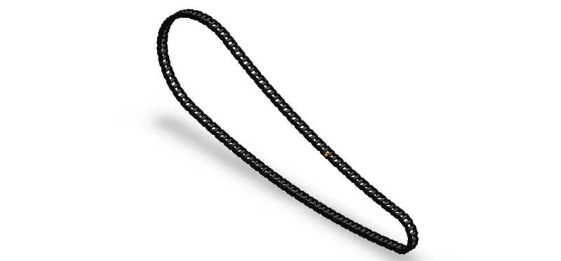
To model chain, first I make 2d sketch for chain path then I make links sketches (inner & outer plates). Now I draw sketch on midplane chain and extrude it 25mm depth about midplane, again I make 2 more extrude for inner & outer plate using 9.5mm from offset and 2.5mm depth for Outer plate & from vertex taking 2mm depth for inner plates. fillet of 0.5mm is applied & Curve driven pattern with 20 instances.Now for next curve I apply 4 no of instances, and 30.26 spacing, the depth is same for inner and outer plates. and for last two curve the Curve driven pattern instances is 23 & 16, with 30.26mm spacing and 0.5mm fillet.
- Features
- Curve driven pattern-The curve driven pattern allows you to create patterns along a planar or 3D curve.
- Mirror-Mirror is used to make another copy of sketches.
- Front Wheel
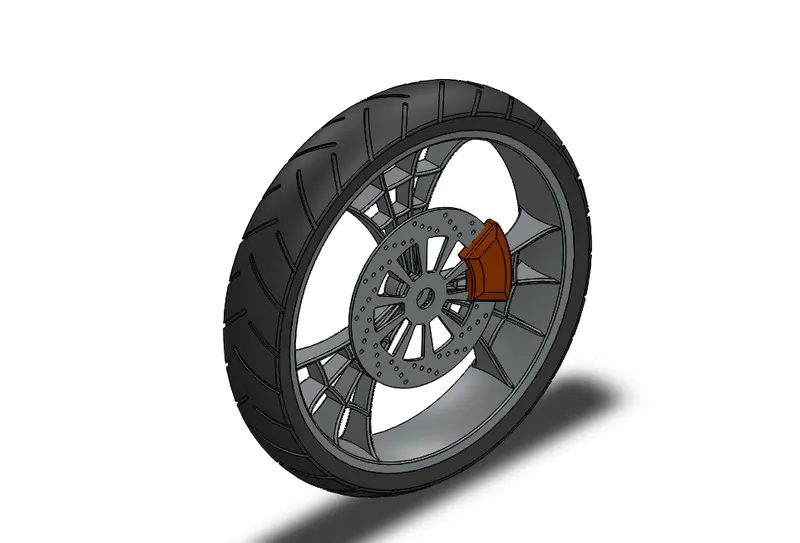
To Model Front wheel, first I design Rim of wheel by using features like Revolve, Boss extrude, cut extrude, Cut Revolve, Circular pattern, combine and Fillet. Now next I design Rotor using same feature as used in Rim, the diameter of Rotor is taken as 345mm and 14 no of instances is taken for circular pattern. Cut extrude applied for axle hole of 40mm diameter. for Caliper design I use boss extrude, chamfer and fillet features.For Tire Design Revolve, Cut Extrude, fillet and Circular pattern applied, the no of instances is 14 for circular pattern.
- Features
- Revolve- Revolves add or remove material by revolving one or more profiles around a centre line. You can create revolved boss/bases, revolved cuts, or revolved surfaces. The revolve feature can be a solid, a thin feature, or a surface.
- Cut extrude- You create an extruded cut in a two-dimensional or axisymmetric planar part by sketching the two-dimensional cross-section of the cut directly on the plane of the part. The cut always passes completely through the part.
- Cut revolve-Use the Revolve tool to remove material by revolving a sketched section around a centreline.To create a cut, use the same angle options as for protrusions.
- REAR WHEEL
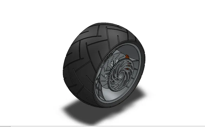
Rim design-To design Rear wheel first I make 2d sketch for Revolve, then I make extruded boss/base of 300mm depth across mid plane, cut extrude using through all both feature, boss extrude again using up to vertex feature in direction 1, Circular pattern with 3 no of instances, equal spacing and 360degree angle, combine feature also used, Cut revolve used to give rim a Curve design, fillet of 2mm is used, a cut is created using cut extrude of 60mm diameter for axle.
Rotor design- To design Rotor I make circle of 320mm diameter, now Boss extrude using offset value of 105mm, and 7mm depth is created. I create cut extrude for rotor holes, circular pattern with 14 no of instances, equal spacing and 360degree angle is applied. Another cut extrude is created for big holes on rotor, fillets of 5mm radius applied on inside edge of cut created, Circular pattern with 9 no of instances, equal spacing and 360degree angle is created.
Caliper design-To design caliper first I make 2d sketch profile of caliper and create boss extrude with offset value 3.5mm and depth of 30mm across mid plane, I use two chamfers, 1st chamfer distance is d1- 20mm, d2- 6mm, 2nd chamfer d1- 6mm, d2- 20mm, 8mm radius fillet is applied on two corner edges of caliper, and 4mm radius fillet on rest edges.
Sprocket design-To design sprocket I make circle of 300mm diameter, and create boss extrude of 15mm depth, Chamfer of 4mm distance and 45degree angle is applied. I make cut extrude for sprocket teeth using through all features, 2.20mm fillet is applied. Circular pattern with 60 no of instances, and equal spacing is applied.Two cut Extrude for cut on sprocket is created using through all feature
Tire design-To design tire, 2d sketch profile for revolve is drawn, for tire tread Cut extrude is applied of 400mm offset value, and 6mm distance offset from surface. 4mm fillet is applied on inside edges, circular pattern with 9 no of instances and equal spacing is applied.
Feature
- Boss Extrude
- Cut extrude
- Revolve cut-The revolved cut tool allows you to cut a profile around an axis creating complex geometry in a single feature.
- Circular pattern-The circular pattern command is an excellent tool used to replicate features, faces, or bodies in a rotational manner about an axis.
- Fillets and chamfer
- FRONT FORK
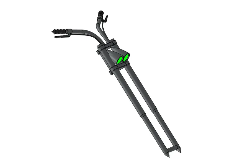
To model Front fork first I make suspension using revolve feature, then I make Fuel meter using Boss extrude, fillet & Linear pattern. Now Wheel Axle rod & Chassis axle rod is made using boss extrude.Now I apply revolve for headlight, Cut extrude of 10mm depth & 5degree is applied, fillet of 3mm & dome of 7mm is applied. another fillet of 1mm radius is applied to inside edge. A Revolve cut is applied, Now I use move command to move the Headlight. Now I draw 2d sketch on top plane & front plane to make projected curve for Sweep.
Reference plane 1-On Plane 1, I draw 2d sketches and apply revolve 1 & Revolve 2.
Reference plane 2-On plane 2, I apply Boss extrude of 15mm depth, fillet of radius 25mm, 15mm, and 4mm. A projected curve is made for Brake & Clutch wire & Sweep is applied.
Fork midplane- On fork midplane I apply Mirror and combine feature.Now I apply reference plane and name as vertical plane front fork selecting top plane as first reference, with 59degree angle and Axle axis as 2nd reference.
FEATURE
- Boss extrude
- Revolve
- Linear pattern
- Extruded cut
- Dome
- Cut revolve
- Projected curve
Projected curve-It is a tool to form 3d curves from two 2d curves from two different planes.
- GAS TANK
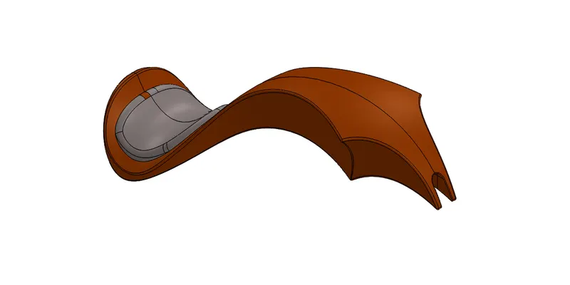
Gas tank is designed using Surface modelling Features like Surface sweep, Surface trim, Projected curve, surface loft and Boundary surface.
Reference Plane 1-First I make surface sweep from 2d sketches. then I draw another 2d sketch to trim the surface.
Reference plane 2- Here I apply projected curve & Surface loft feature.
Reference plane 3- On Reference plane 3, I apply Boundary surface 1 & 2, Mirror, surface knit, split, surface extrude feature, surface loft, sweep cut, fillet and shell feature. The radius of fillet 20mm, & 5mm, the shell is of 3mm thickness.
Feature-
- Surface sweep-Sweep Surfaces are surfaces that are generated from a section curve positioned along a path. ... Parallel Sweep is defined as a section curve moving along a guide path while maintaining the section curve to be parallel to the guide path.
- Surface loft-Loft Surfaces are surfaces generated by multiple 3D Curves or existing edges creating a smooth tangency between the selected curves. Match Points are created between each selection denoting the orientation and path of the loft surface.
- Boundary Surface-The boundary surface feature lets you create surfaces that can be tangent or curvature continuous in both directions (all sides of the surface). In most cases, this delivers a higher quality result than the loft tool.
- Sweep cut-Solidworks swept cut is features tool, mainly used to cut a solid model or part by sweeping a completely closed profile along an open or closed path. To use swept cut, you should need a closed profile and open or closed path, which may be line, helix, and circle, rectangular or arc etc.
- CHASSIS
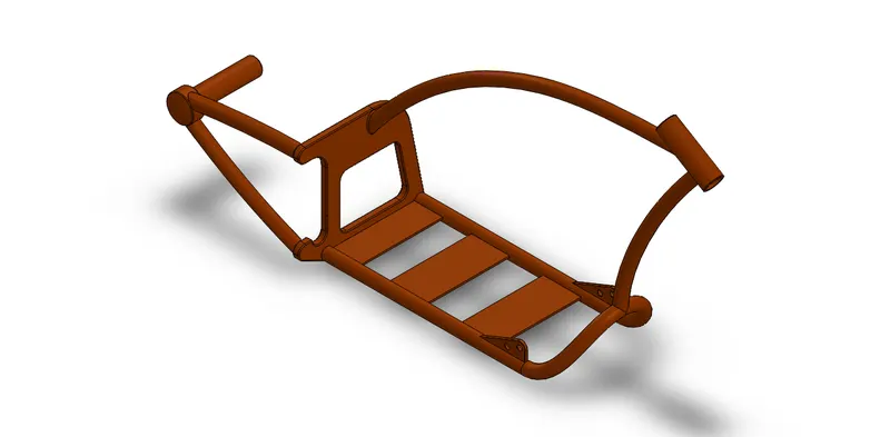
To model Chassis, first I make projected curves using 2d sketches, then I apply sweep and Mirror, I apply Boss Extrude ,Cut extrude, Chamfer & fillets.Now I draw Reference plane 1 & apply Sweepes, Boss Extrudes, and Dome features. Again I draw Reference plane 2 and apply sweep for Top tube and split. On Reference plane 3, I apply sweep for down tube, split and combine features.Now I apply Revolve for Head tube, split and combine feature.Now I make plates on which engine is mounted by Boss extrudes using upto next option, and 2mm fillet is applied.
Pedal Mounting-To mount pedal I make mounting area by applying boss extrude of offset 165mm and 10mm depth.split is applied, fillet of 20mm and 1mm radius is applied on corner and edges.Mirror and combine feature also applied.
Kickstand Mounting-To mount kickstand, I apply 40mm depth Boss extrude, 3mm radius fillet and face fillet. A extrude cut is applied of 12mm diameter.
Bottom plane fuel tank-First reference as Bottom plane chassis and 308mm offset distance, I draw a 2d sketch and apply split feature and 3mm radius fillet.
Features
- Boss extrude
- Sweep
- Split
- Mirror
- Combine
- Projected curve
- Engine
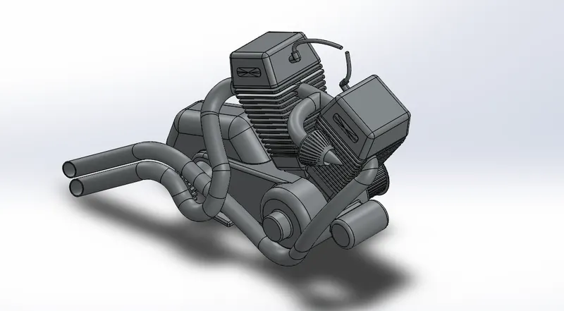
To design engine first I use Blueprint of chopper with X=- 1493, Y=-965 values, then I make Motor housing by using four extruded boss Base of 200mm, 50mm, 40mm, and 150mm depth. Now I apply 50mm radius fillet on back portion edges. Now I apply revolve feature to make front pulley, and Back pulley.I draw 2d sketch to make boss extrude for pulley teeth, and use circular pattern with 40 instances, & equal spacing, same for back pulley with 44 instances. 10mm dome is applied.Now I Apply cut extrude of 250mm offset value & 3mm offset distance, for both Pulley. Chamfer of 3mm distance & 45degree angle is applied and fillet of 1mm applied.
Starter-I draw 2d sketch for starter and apply boss extrude of 150mm depth about midplane, other extrude of 110mm depth.
Cylinder design-To design cylinder first I draw 2 lines of 102mm, and 240mm length, from origin and 64degree angle. Now I create a reference plane and draw sketch on it Using center point rectangle from midpoint of 190mm*190mm. Now I extrude this sketch using up to vertex and 7.5degree draft.Now I sketch on end face using center point rectangle of 100*100mm. extrude using up to Next. I select boss extrude 10 sketch and extrude it with 125mm depth.Chamfer with distance-distance is applied d1-90mm, d2-15mm on top edges. Fillets of 15mm is applied on all edges of cylinder.
Cooling fins-For cooling fins I draw new sketch on plane 2 which is center point rectangle of 120*120mm & 220*220mm. fillet applied on inside edges of sketch of 10mm. Now extrude cut applied here with offset of 26mm and direction 1 of 8mm, linear pattern of 14 instances and 16mm distance is applied. 2mm fillet applied on inside and outside edges.10mm fillet applied on outside edges of engine case and starter. 5mm fillet to inside edges connected starter to engine.
Cylinder valve cover-First I make 2d sketch on cylinder face, and apply boss extrude of 2mm depth. Dome of 2.5mm is applied and mirror it.
Spark plug-To model spark plug I draw 2d sketch first and apply 20mm depth boss extrude, 10mm & 2.5mm fillet is applied. Now I use split & Mirror feature, again 25mm & 4mm fillet is applied to the edge of motor housing.
foot of engine-Now I apply 50mm & 12mm depth boss extrude to make base part of engine which is joined with Chassis.and apply 5mm & 2mm radius fillets to inside edges.
Sprocket-First 2d sketch is drawn then I apply Boss extrudes of 15mm & 85mm depth, a chamfer of 4mm distance & 45degree angle is applied.Cut extrude, fillet of 2.20mm radius and circular pattern with 21no of instances is applied.I applied Chamfer with distance-distance feature of 24mm & 75mm distance another chamfer of 5mm distance and 45degree angle.
Air Filter-To model Air filter I apply sweep,Mirror & combine feature. Now I make Reference plane and apply sweep, Revolve, fillet of 5mm radius, Cut extrude of 2mm offset and Circular pattern with 30 instances.
Composite curve 1-First I make two projected curves, then I make reference plane and apply Composite curve, & sweep feature.
Composite Curve 2-Again I make Projected curves by drawing two 2d sketches, now A Reference plane is drawn and projected curve is applied then Composite curve is applied.
Now I make reference plane and apply sweepes for 2nd exhaust, andspark plug wires.
Features
- Boss Extrude
- Cut Extrude
- Circular Pattern
- Revolve
- Reference plane
- Linear pattern
- Sweep
- Mirror
- Combine
- Projected Curves-It is a tool to form 3d curves from two 2d curves from two different planes.
- Composite curve-A composite curve is created by combining curves, sketch geometry and model edges into a single curve.
ASSEMBLY OF CHOPPER-Now I assemble the all parts Using standard Mates, like Concentric,Coincident, distance, lock,parallel, angle, and tangent mates. The assembly order is shown below
- CHASSIS
- ENGINE
- PEDAL
- KICKSTAND
- TRANSMISSION BELT
- REAR WHEEL
- REAR FENDER
- CHAIN
- GAS TANK
- FRONT FORK
- FRONT WHEEL
- FRONT FENDER
- OIL TANK
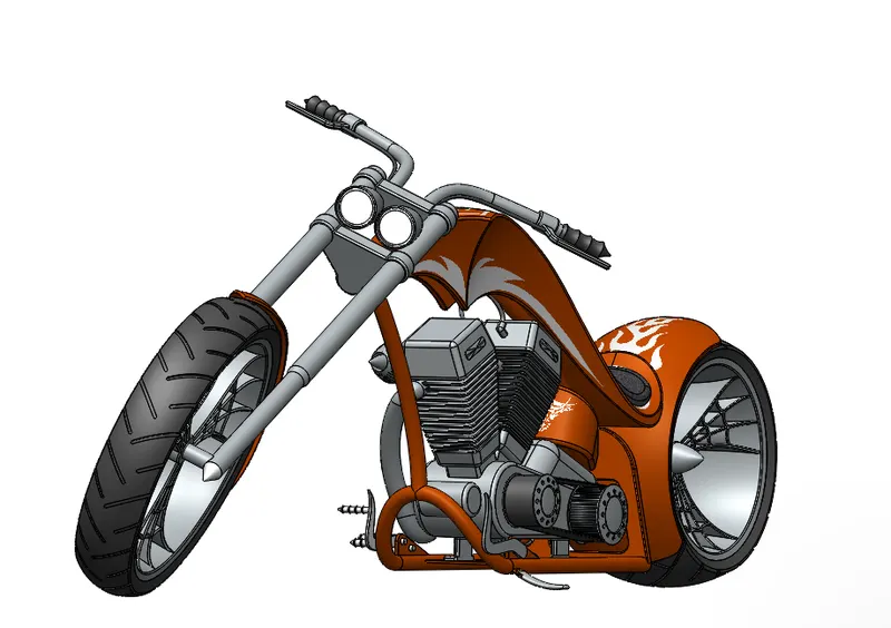
RENDERING OF CHOPPER-For Rendering Of Chopper I use Photoview 360, and placed decals on Gas tank, Rear fender and oil tank.I Choose Siena Color as appearance.To do final rendering first I do,
- Rendering Setting the chopper up in our Environment
- Rendering Adding decals to our chopper
- Rendering adjusting colors and editing material
- Scene composition
- Rendering scene setup
- Rendering of lights
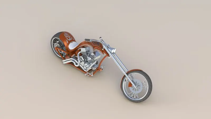
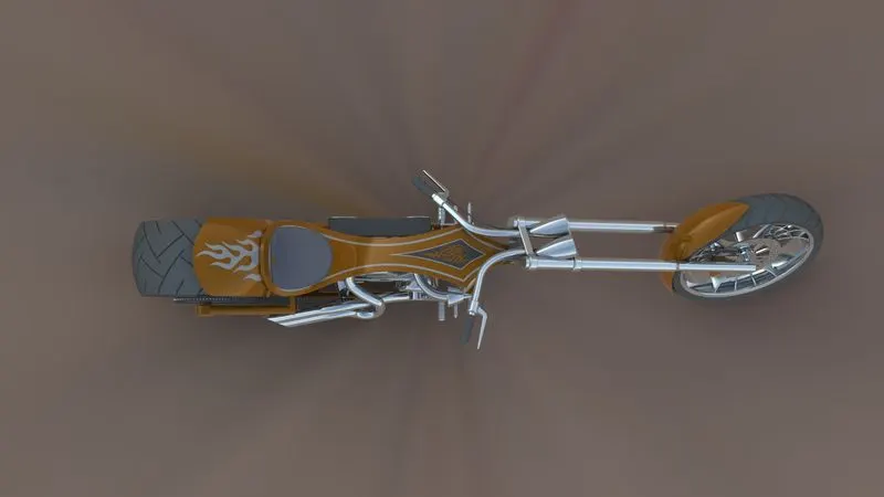
ISOMETRIC VIEW TOP VIEW
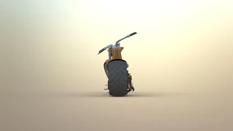
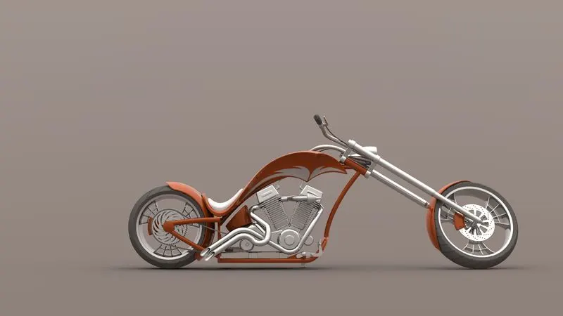
SIDE VIEW FRONT VIEW
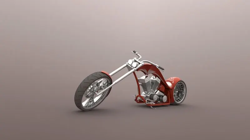
CAMERA VIEW
Conclusion-I Design & Model all parts of American Chopper, Assemble the parts of Chopper and Do Final Rendering Using Photoview 360.