Photo Realistic Rendering
https://drive.google.com/drive/folders/1-u-L4rRRc1w6C6A8rk3PU75wzlFJMNKT?usp=sharing
PROJECT REPORT
AMERICAN CHOPPER
Aim:
To sketch all parts of an American Chopper and assemble all the parts together by using Solid works.
Objectives:
- To sketch all the parts of an American Chopper with fully defined.
- To assemble all parts of an American Chopper with fully defined.
- To render the assembly by Photo view 360o and to know all rendering options.
Procedure:
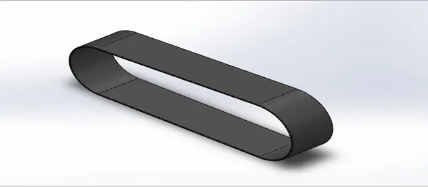
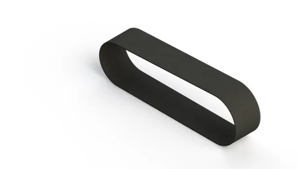
- Transmission Belt
It is a belt which is used to transfer power from one shaft to another.
Tools used:
- Extrude
- Fillet
CAD Model image:
Rendered image:
- Kick stand
It is a metal bar or rod attached to a bicycle or motorcycle that is used to support the vehicle when it is stationary and when it is not in use.
Tools used:
- Loft
- Dome
- Extrude Cut
- Split
- Extrude
- Fillet
CAD Model image:
Rendered image:
- Front Fender
It is a part of an automobile which is used to prevent mud, rock, liquids and other particles in the road from being thrown into the air by the front rotating tire.
Tools used:
- Revolve
- Split
- Fillet
CAD Model image:
Rendered image:

- Rear Fender
It is a part of an automobile which is also used to prevent mud, rock, liquids and other particles in the road from being thrown into the air by the rear rotating tire.
Tools used:
- Revolve
- Split
- Fillet
- Shell
CAD Model image:
Rendered image:
- Oil Tank
It’s primary function is to store oil in the tank and pump it into an internal combustion engine.
Tools used:
- Extrude
- Combine
- Fillet
- Shell
CAD Model image:
Rendered image:
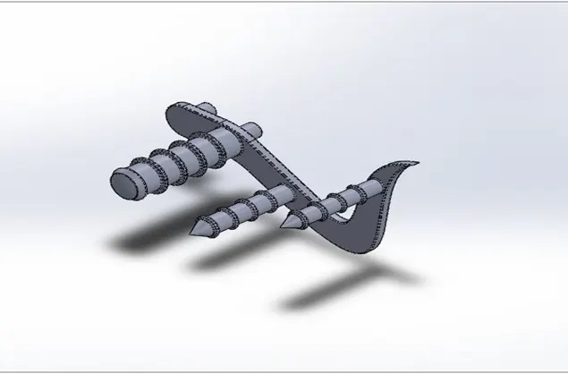
- Pedal
It is a pair of foot – operated levers used for powering a bicycle or other vehicle propelled by the legs.
Tools used:
- Extrude
- Fillet
- Revolve
- Dome
- Chamfer
- Linear Pattern
CAD Model image:
Rendered image:
- Chain
It is a way of transmitting mechanical from output shaft of the transmission to the rear wheel and often used to convey power to the wheels of a vehicle.
Tools used:
- Extrude
- Fillet
- Curve Driven Pattern
- Mirror
CAD Model image:
Rendered image:
- Front Wheel
It is steer-able, which means that power has to be transmitted at very variable angle.
Tools used:
- Revolve
- Extrude
- Extrude Cut
- Revolve Cut
- Circular Pattern
- Combine
- Fillet
- Chamfer
CAD Model image:
Rendered image:
- Rear Wheel
The entire weight of the bike is on the rear wheel and where power is applied and it makes them driven wheel.
Tools used:
- Revolve
- Extrude
- Extrude Cut
- Circular Pattern
- Combine
- Revolve Cut
- Fillet
- Chamfer
CAD Model image:
Rendered image:
- Front Fork
It is where the front wheel is connected and act as large hydraulic shock absorbers with internal coil springs.
Tools used:
- Revolve
- Extrude
- Fillet
- Linear Pattern
- Extrude Cut
- Dome
- Curve
- Sweep
- Combine
CAD Model image:
Rendered image:
- Engine
It is used to convert power to produce motion and force. In motorcycle we use internal combustion engine, which burn a fuel to create heat and then used to do work.
Tools used:
- Extrude
- Fillet
- Revolve
- Circular Pattern
- Dome
- Extrude Cut
- Chamfer
- Linear Pattern
- Mirror
- Split
- Sweep
- Combine
- Composite Curve
CAD Model image:
Rendered image:
- Chassis
It is a base frame of the vehicle at which engine, pedal, rear wheel, front fork are mounted.
Tools used:
- Curve
- Sweep
- Mirror
- Extrude
- Extrude Cut
- Chamfer
- Fillet
- Sweep
- Dome
- Split
- Combine
CAD Model image:
Rendered image:
- Gas Tank
It is a tank which is attached in vehicle and where the driver seat is also placed.
Tools used:
- Surface Sweep
- Surface Trim
- Curve
- Surface Loft
- Boundary Surface
- Mirror
- Surface Knit
- Split Line
- Surface Extrude
- Fillet
- Sweep Cut
- Shell
CAD Model image:
Rendered image:
- Chopper Assembly
All parts of the American Chopper had done and assembly of the Chopper parts are done with different mates.
Mates used:
- Midplane mate
- Tangent
- Coincident
- Parallel
- Distance mate
- Angle mate
- Width mate
- Concentric
- Mirroring of Pedal
Assembly image:
Rendered image:
- Rendering
It is the process of generating the photo realistic image from 2D or 3D models. It is also process of adding camera, decals and light to the model, giving it realistic appearance.
Tools used:
- Edit Appearance
- Edit Scene
- Edit Decal
- Integrated Preview
- Preview Window
- Final Render
- Option
- Schedule Render
- Camera
- Light
Conclusion:
Before starting the course, I thought that it was easy but it was very challenging to complete the parts of the American Chopper. During challenges, I had learned about how to use project curves, split tool, dome, and combine options. I also had known about rendering and different mating options.
This course is really helped to improve my skills in Solid works.