Photo Realistic Rendering
SKILL – LYNC
Design Engineer Master's Certification Program
Module -1 Ultimate SOLIDWORKS Course
Challenge – 8 Photo Relastic Rendering
American Chopper Final Report
Aim:
The main aim of the project is to design an American Chopper to get accustomed to various designing techniques: Solid Modelling, Surface modelling, Assembly and Rendering.
Intoduction:
This report contains the complete procedure for designing an American Chopper starting from components to final render using CAD software ( Solidworks)
Methodology:
- Components Design
- Assemble the components
- Apply Materials, Paint & Decal
- Render the final model
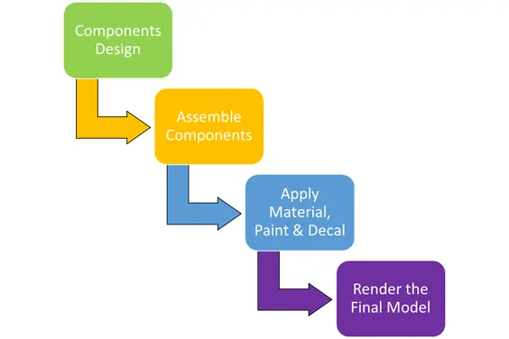
Fig 1 : Methodology
Components List:
- Chassis
- Engine
- Wheels (Front & Rear)
- Fork
- Gas Tank
- Oil Tank
- Fenders (Front & Rear)
- Pedal
- Chain
- Kick Stand
- Transmission Belt
Sketch Tool & Features Used:
- 2 D Sketch - 2 D sketch forms the base to design or to model components in 3 D. 2 D sketching includes - Lines, Circles, Splines, Arcs, Rectangle and etc.
- Trim - Trim tool removes the excessive sketch which are not required.
- Convert Entites - Converts 3 D model's sketch onto a desired plane for sketching.
- Offset - Offsets the sketch from center to either one side or both the sides for a specifed distance.
- Mirror - Mirrors faces, featurer and body about a face or a plane.
- Extrude Boss/Base - Extrudes a 2 D sketch in specified direction creating solid bodies.
- Revolved Boss/Base - Revolves a 2 D sketch around an axis creating a solid body or feature.
- Sweep - Sweeps a closed profile along an open or a closed path to create solid feature.
- Revolved Cut - Cuts a solid model by revolving a sketched profile around an axis.
- Loft - Adds material between two or more profile to create a solid feature.
- Fillet - Creates a rounded internal or external faces along one or more edges in solid or surface feature.
- Chamfer - Transitional edge between two faces of an object.
- Combine - Combines two or more solid bodies together.
- Dome - Adds one or more domes to selected planar or non planar faces.
- Shell - Removes material from a solid body to create a thin walled feature.
- Projected Curves - Creates a 3 D curve.
- Extend Surface - Extends the edge or multiple edges or the face on a surface, based on end conditions and extension type.
- Ruled Surface - Inserts ruled surfaces from the edges.
- Offset Surface - Creates offset surfaces using one or more contiguous faces.
- Boundary Surface - Creates a boundary surface between profiles in two directions.
- Lofted Surface - Creates a lofted surface between two or more profile.
- Trim Surface - Trims a surface where one surface inersects with another surface, a plane, or a sketch.
Images of the Features Used:
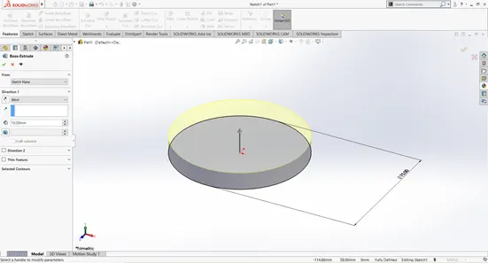
Fig 1 : Extrude
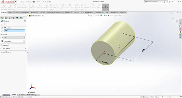
Fig 2 : Revolve
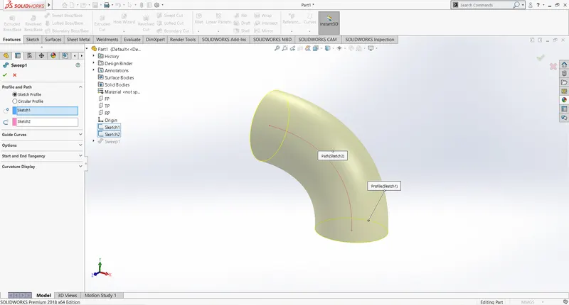
Fig 3 : Sweep
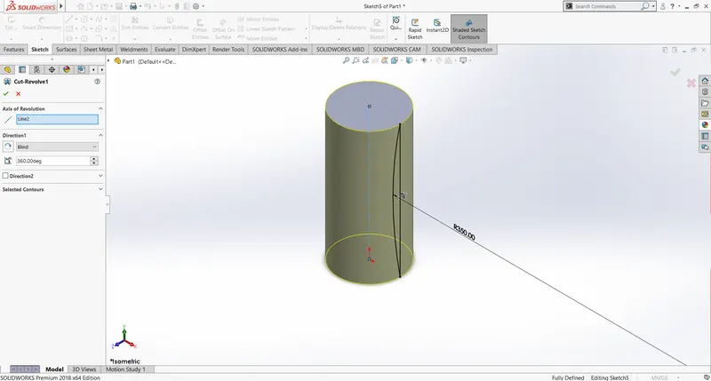
Fig 4 : Revolve Cut
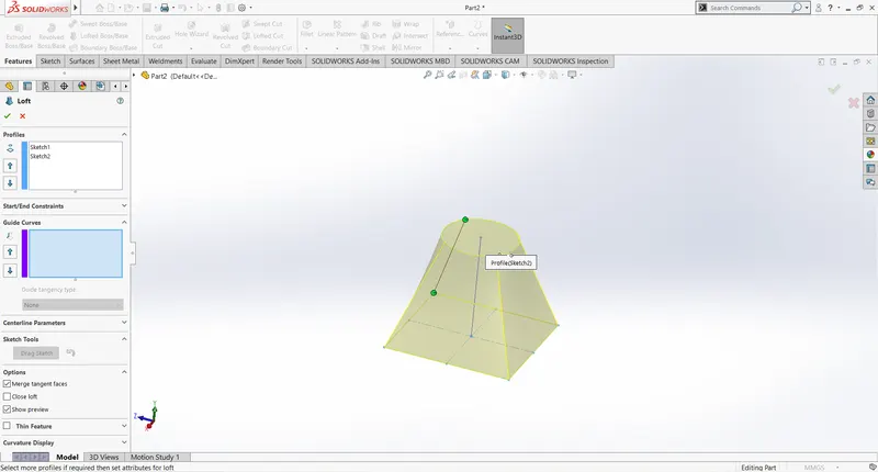
Fig 5 : Loft
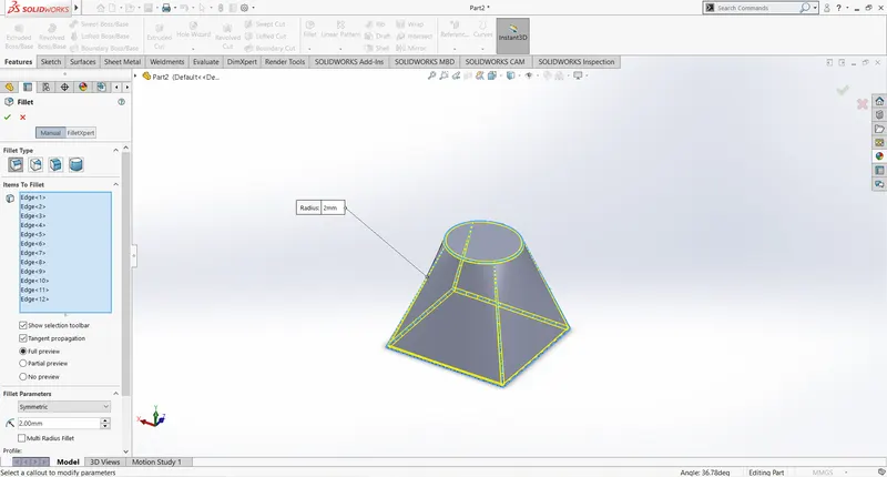
Fig 6 : Fillet
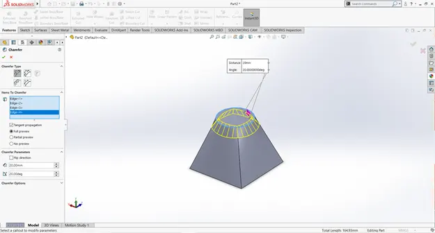
Fig 7 : Chamfer
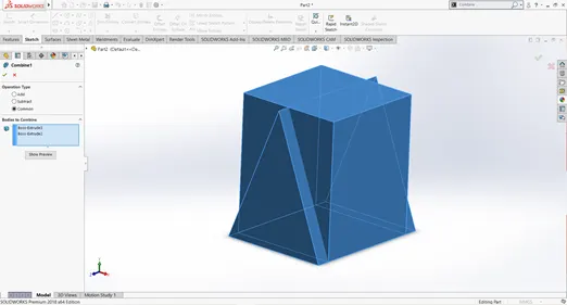
Fig 8 : Combine
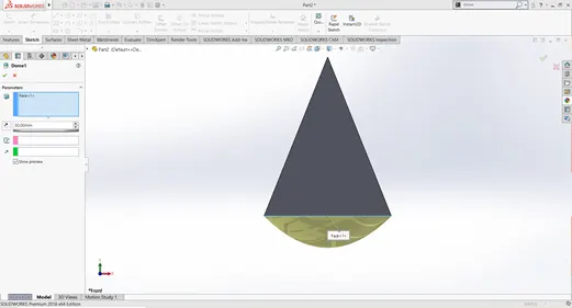
Fig 9 : Dome
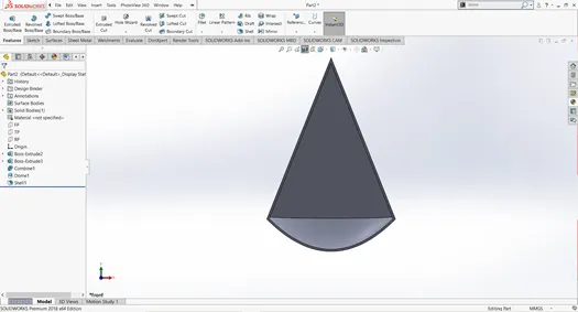
Fig 10 : Shell
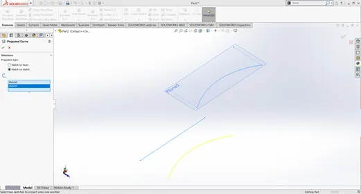
Fig 11 : Projected Curve
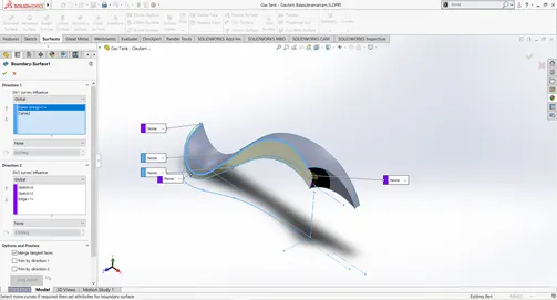
Fig 12 : Boundary Surface
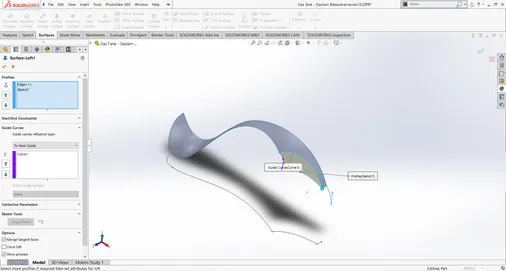
Fig 13 : Surface Loft
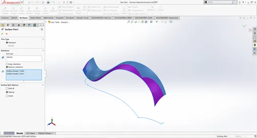
Fig 14 : Trim Surface
Components:
1. Chassis
Chassis is the base of all automobiles let it be 2 wheeler or 4 wheeler. All the components are assembled on to the chassis, and also they play a major role in vehicle dynamics. So when designing a chassis, lot of aspects has to be considered like safety, manufacturablity, dynamics of the vehicle etc.
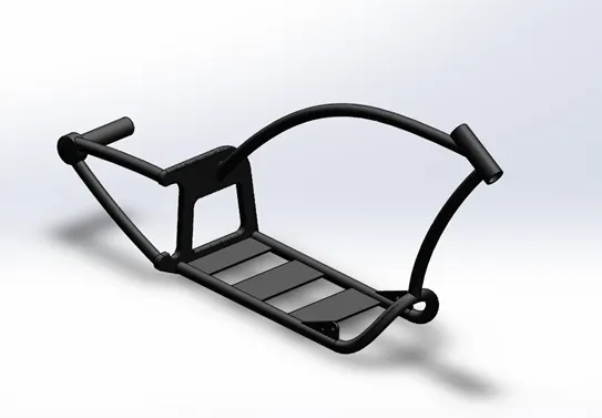
Fig 15 : 3 D Model of the Chassis
Learning Out Comes:
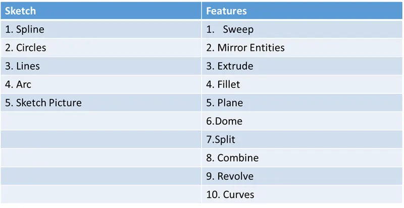
Fig 16 : Sketch & Feature used for Chassis
2. Engine
Engine had been and will be the source of power for any automobile. They turn air and fuel mixture into mechanical energy.
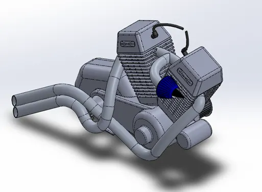
Fig 17 : 3 D Model of the Engine
Learning Out Comes:
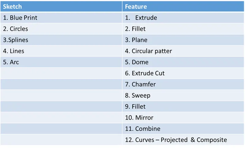
Fig 18 : Sketch & Feature used for Engine
3. Wheels ( Front & Rear)
Wheels are the point of contact between the ground and the entire automobile. They play a major role of delivering the power produced by the engine to the ground.
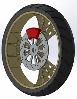
Fig 19 : 3 D Model of the Front Wheel
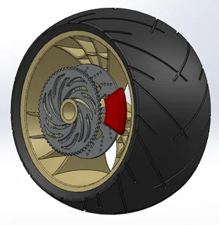
Fig 20 : 3 D Model of the Rear Wheel
Learning Out Comes:
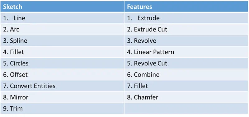
Fig 21 : Sketch & Feature used for Wheels ( Front & Rear)
4. Fork
Front fork are the contact between the rider and the front tyre. All the inputs provided by the rider like throttle, brakes and direction change are transfered from forks to the invidual componenet.
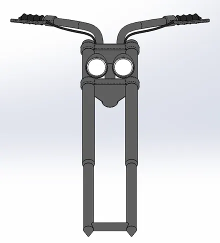
Fig 22: 3 D Model of the Front Fork
Learning Out Comes:
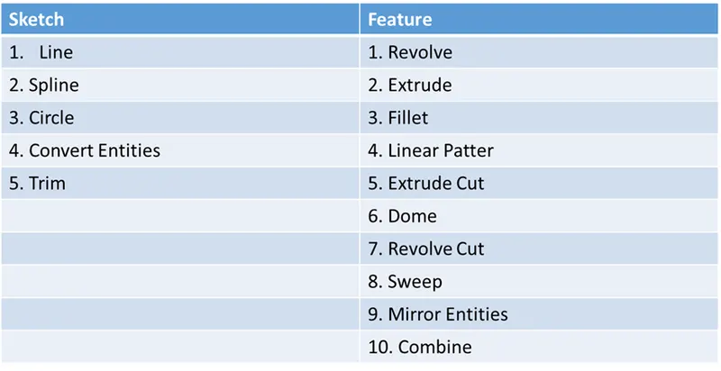
Fig 23 : Sketch & Feature used for Front Fork
5. Gas Tank
Gas tank store the fuel that is required by the engine for the combustion purpose. When it comes to designing a gas tank they main aspect to consider would be the strength of the material for the safety and dynamics of fuel slushing inside the gas tank.
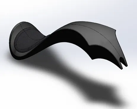
Fig 24 : 3 D Model of the Gas Tank
Leaning Out Comes:
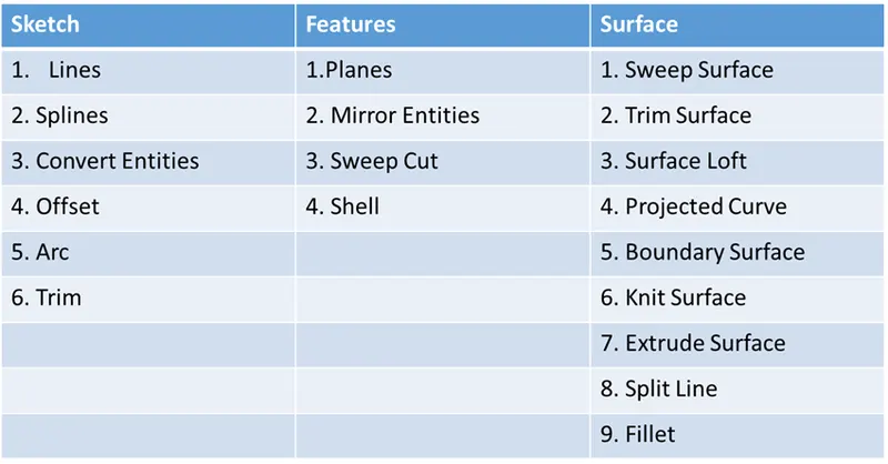
Fig 25 : Sketch & Feature used for Gas Tank
6. Oil Tank
Oil tank stores the oil that is required for lubrication for all the mechanical components like engine and gear box.
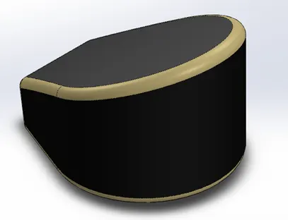
Fig 26 : 3 D Model of the Oil Tank
Learning Out Come:
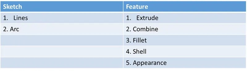
Fig 27 : Sketch & Feature used for Oil Tank
7. Fenders (Front & Rear)
Fenders act as barrier between the componenets and the debries that are thrown by the tyre.
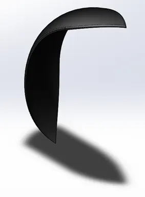
Fig 28 : 3 D Model of the Front Fender
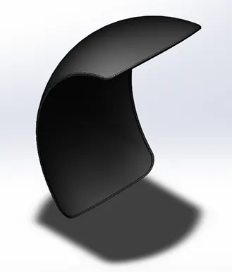
Fig 29 : 3 D Model of the Rear Fender
Learning Out Comes:
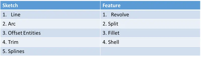
Fig 30 : Sketch & Feature used for Fender ( Front & Rear)
8. Pedal
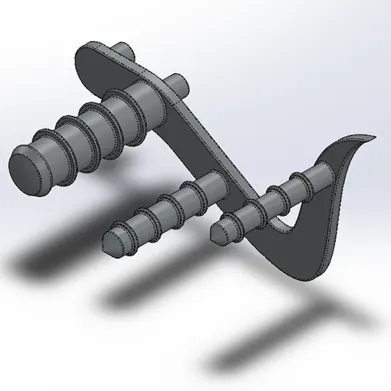
Fig 31 : 3 D Model of the Foot Pedal
Learning Out Comes:
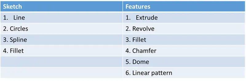
Fig 32 : Sketch & Feature used for Foot Pedal
9. Chain
Chain transfers power from gear box to the rear wheel.
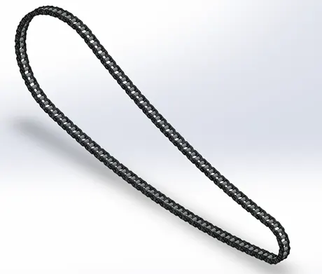
Fig 33 : 3 D Model of the Chain
Learning Out Comes:
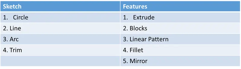
Fig 34 : Sketch & Feature used for Chain
10. Kick Stand
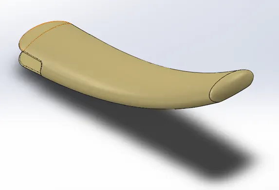
Fig 35 : 3 D Model of the Kick Stand
Learning Out Comes:
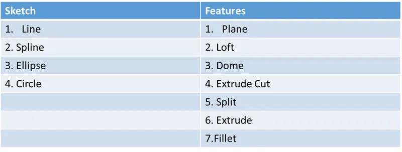
Fig 36 : Sketch & Feature used for Kick Stand
11. Transmission Belt
Transmission belt transfers power from engine to gear box.
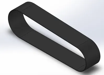
Fig 37 : 3 D Model of the Transmission Belt
Learning Out Comes:

Fig 38 : Sketch & Feature used for Transmission Belt
Assembly:
- Chassis forms the base for assembling all the componenets.
- Most of the components like wheels froks and engine shares the planes of the chassis for mating.
- Also the other components use mates like concentric, parallel etc upon which the componenet has to be assembled.
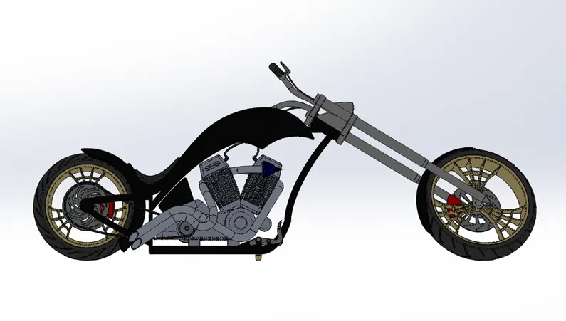
Fig 39 : 3 D Model of the assembled American Chopper (Front View)
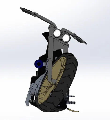
Fig 40 : 3 D Model of the assembled American Chopper ( Side View)
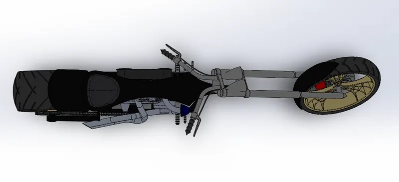
Fig 41 : 3 D Model of the assembled American Chopper ( Top View)
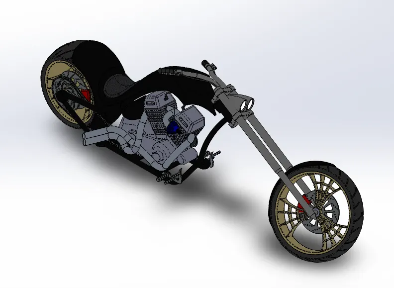
Fig 42 : 3 D Model of the assembled American Chopper ( Isometric View)
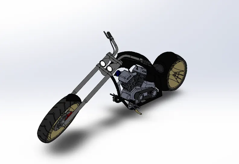
Fig 43 : 3 D Model of the assembled American Chopper ( Camera View)
Apply Materials, Paint & Decal:
- Once the componenets are assembled the materials, paints and decals are applied on to the component.
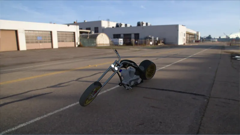
Fig 44 : Rendered image of American Chopper post applying materials, paint and decal in Photo View 360.
Rendering:
- American Chopper was rendered in Solidworks Visualise to create a photo relastic image of the bike.
Redering Process Involves
- Environment setup
- Lighting setup
- Camera setup
- Redering
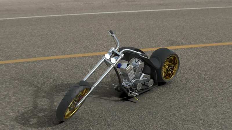
Fig 45 : Rendered image of the American Chopper
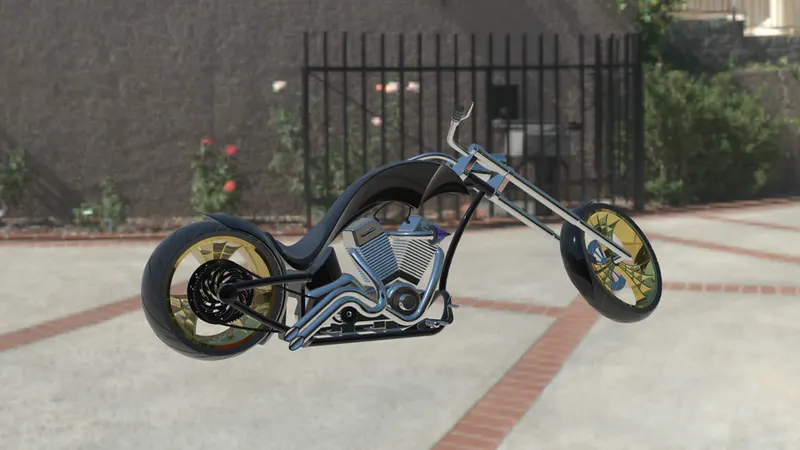
Fig 46 : Rendered image of the American Chopper
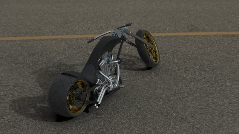
Fig 47 : Rendered image of the American Chopper
Conclusion:
This report gives us a brief procedure on how the American Chopper was designed.
https://drive.google.com/drive/folders/1UFu8dvCeErBYNQssBZWNbq3lCBGZRL1l?usp=sharing