Photo Realistic Rendering
TITLE: Modelling, Assembly and Photorealistic Rendering of American Chopper using SOLIDWORKS
Objective:
- To create the 3D model of an American Chopper using SolidWorks 2020
- To Create the required parts for the American Chopper
- To build the assembly with right configuration
- To create the photorealistic rendering of an American Chopper
Introduction
American Choppers
A chopper is a type of custom motorcycle which emerged in California in the late 1950s. A chopper employs radically modified steering angles and lengthened forks for a stretched-out appearance. They can be built from an original motorcycle which is modified ("chopped") or built from scratch. Some of the characteristic features of choppers are long front ends with extended forks often coupled with an increased rake angle, hardtail frames (frames without rear suspension), very tall "ape hanger" or very short "drag" handlebars, lengthened or stretched frames, and larger than stock front wheels.
Solidworks:
SolidWorks is a solid modelling computer-aided design and computer-aided engineering computer program published by Dassault Systems
This project consists of sketching, features, part modelling of an American chopper model. Added lights and cameras using Photoview 360 add in. Solidworks Visualize is used to add environments and have a quality rendering.
Tool Description:
Sketch:
- Line – It is a tool to draw a line using a start and end point. There are line, centreline, midpoint and construction lines
- Circle- It is a tool to draw a circle using centre point and required end point
- Spline- It is a tool to draw irregular shapes using fit points
- Rectangle—It is a tool used to draw 4 sides. Centre, corner and 3 sided rectangles are used
- Arc- It is a tool used to draw three-pointed arc on basis of position points
- Slot- It is used to create slots with straight and centre point slots
- Ellipse—It is a tool to create an oval shape using 2 snaps
- Trim entities—It is used to trim the unwanted sketches. Free form trim is used
- Convert entities—It is used to convert the required geometries on the sketch plane.
- Offset entities—It is used to offset the required sketches
- Extend- It is used to extend the entities to a required selection
- Mirror- It is used to duplicate the required geometry by planes, lines or axis as reference to mirror about.
- Pattern:
- Linear Pattern: - Its is used to create Linear patterns as copies. It requires direction of pattern, number of copies and distance between the copies.
- Circular pattern: - IT is used to create circular patterns as copies. It requires direction of pattern, number if copies and angle dimensions between copies.
Features:
- Sketch Plane- It is the plane where the sketch is developed
- Extruded Boss/Base- It is used to create solid from the geometry in one or both directions with different contours
- Revolved Boss/Base- It is used to create solid along the axis in different directions with contours
- Extruded Cut—It is used to remove material in a linear manner
- Fillet- It is used to create rounded face internally or externally.
- Chamfer- It is used to create smooth edges for a model
- Pattern: -
- Linear Pattern: - It is used to create multiple copies in linear manner by inputting direction, number of copies and distance between copies.
- Circular Pattern: - It is used to create multiple copies in a circular manner by inputting dicetion , number of copies and angle dimensions.
- Mirror- It is used to create copies by referring a line or a plane to mirror about.
- Shell- It is used to create a hollow surface leaving behind a thin layer feature
- Reference- It consists of plane, axis, curves etc to create a reference which helps to create different geometry.
- Split- It is used to create multiple bodies from a single existing body.
- Combine- It is used to combine 2 or more bodies to a single body.
- Dome- It is used to create one or more dimes for a model.
Surface:
- Sweep surface- It used to generate surface of a sketch along a path
- Loft surface – It generates surface using multiple sketches of different geometry along specified path
- Projected curve- It is used to create a 3D curve using multiple 2D curves.
- Knit surface- It is used to combine multiple surfaces
- Trim surface- It is used to intersecting surfaces
Parts of American Chopper:
- Transmission Belt
- Kickstand
- Front Fender
- Rear Fender
- Oil tank
- Chain
- Pedal
- Front Wheel
- Rear Wheel
- Front Fork
- Chassis
- Engine
- Gas Tank
Description:
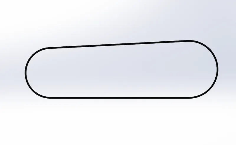
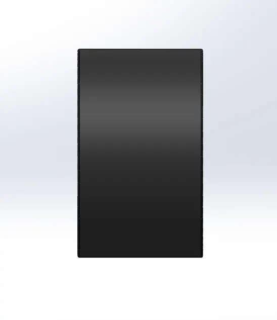
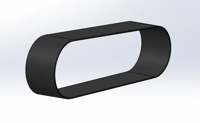
Transmission Belt:
Sketch Commands:
- Line
- Arc
- Offset Entities
- Smart Dimensions
Feature Commands:
- Sketch Plane
- Boss Extrude
- Fillet
- Appearance
Steps for Modelling Transmission Belt:
- First selecting the plane to be sketched on and by using line and arcs drawing required geometry and giving dimensions using smart dimensions.
- Using relations and making the lines and arcs tangent with each other. The entire sketch is Offsetted using Offset entities
- The sketch is extruded using Extrude boss feature and the sharp edges are removed by applying fillets.
- Appearance feature is used to add material and colour to it.
Kick Stand:
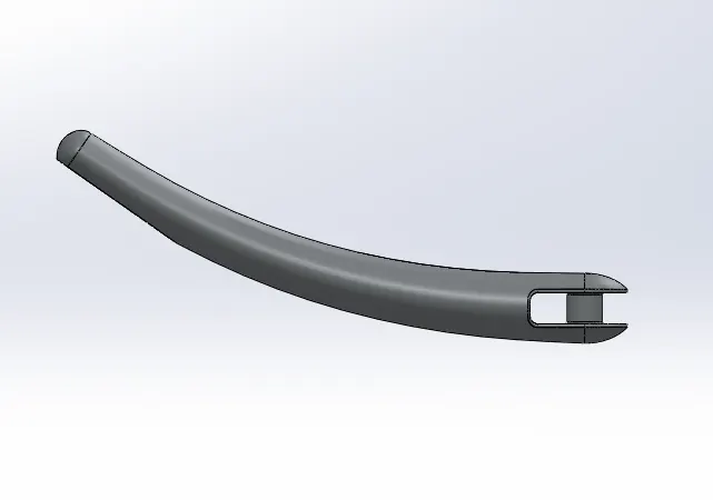
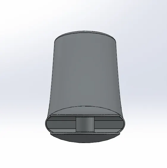
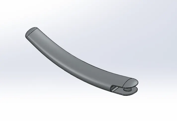
Sketch commands
- Line
- Splines
- Ellipse
- Circle
- Rectangle
- Smart dimensions
Feature commands
- Reference plane
- Loft
- Extrude cut
- Dome
- Split
- Extrude boss
- Fillet
Steps for modelling Kick Stand:
- At first the plane is selected to be sketch the first Ellipse of required dimension and a reference plane is taken to draw a second ellipse.
- Spline is drawn connecting two ellipses.
- Loft feature is used to create solid material between ellipses by using guide curves and Split command is used to remove unwanted material.
- At one edge a Rectangle is drawn and given dimensions using smart dimensions. Extrude cut is used to remove the material. Circle is used to add material.
- By using Fillet feature the sharp edges are removed.
Front Fender:
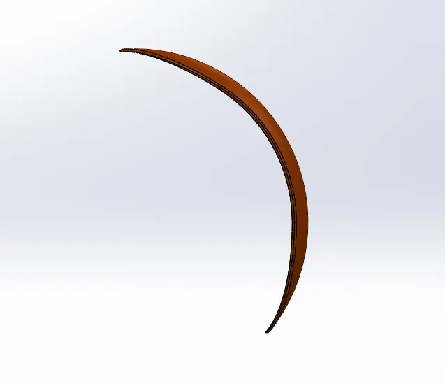
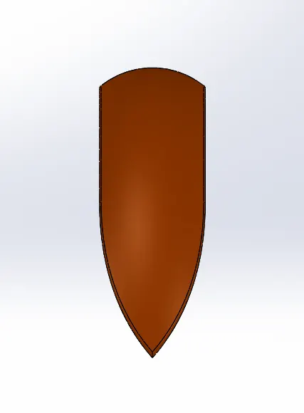
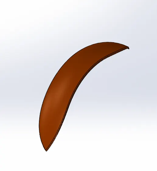
Sketch Commands
- Lines
- Arc
- Offset Entities
- Trim
- Extend
- Splines
- Smart Dimensions
Feature Commands
- Reference axis
- Revolve
- Split
- Fillet
Steps for Modelling Front Fender:
- At first required Plane to be sketched is chose and Arc is created and both edges are made horizontal with appropriate dimensions using smart dimensions.
- The sketch is drawn inwards using Offset entities and extended using Extend Trim command is used to trim unwanted sketch.
- The sketch is revolved using Revolve command for some angle in both directions using a Reference axis.
- The Splines are created from both edges and by using Split unwanted materials are removed.
- Fillet is used to remove sharp edges.
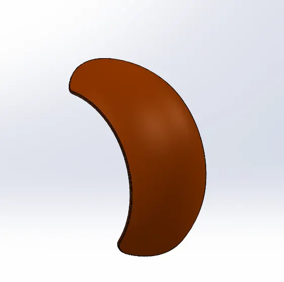
Rear Fender:
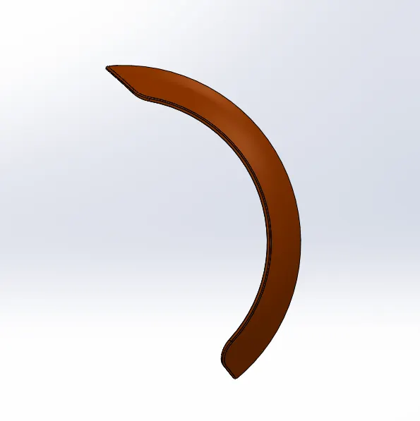
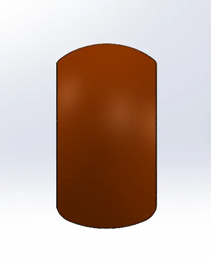
Sketch Commands
- Lines
- Arc
- Splines
- Offset entities
- Trim
- Extend
- Smart dimensions
Feature Commands
- Reference Axis
- Revolve
- Shell
- Fillet
Steps for Modelling Back Fender:
- A Plane is selected for the sketch. Arc is created and both edges are made horizontal with appropriate dimensions using Smart dimensions.
- The whole sketch drawn inwards using Offset entities, the edges are extended using Extend The unwanted geometry is removed using Trim command.
- The sketch is revolved with appropriate angles I booth directions using Revolve
- Fillet is used to remove the sharp edges.
- Shell is used to create hollow thickness using appropriate thickness.
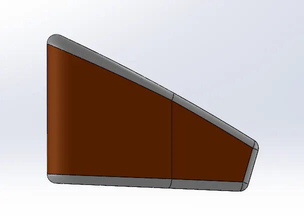
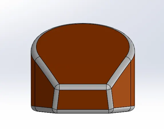
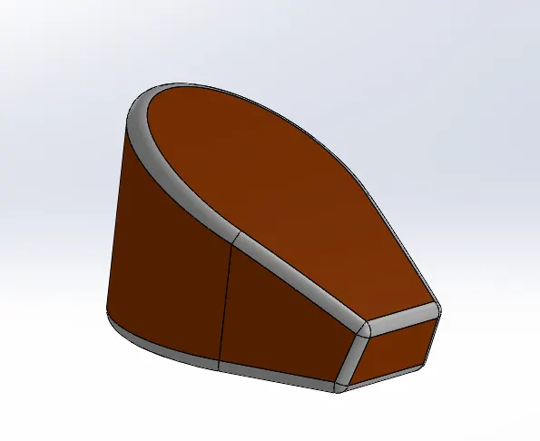
Oil Tank:
Sketch Commands
- Lines
- Splines
- Smart Dimensions
Feature Commands
- Boss Extrude
- Combine
- Fillet
- Shell
Steps for Modelling Oil Tank:
- A required Plane is selected to draw lines, arc with relations and appropriate dimensions using Smart dimensions.
- The whole sketch is extruded using Extrude Boss command from midplane and Combine feature is used to combine the two features.
- Fillet is used to remove the sharp edges.
- Shell is used to create the hollow surfaces with thin feature of required dimensions.
Pedal:
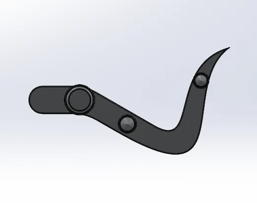
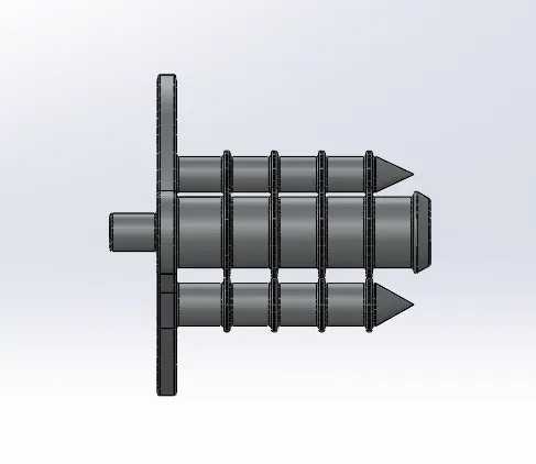
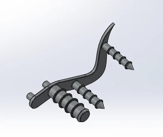
Sketch Commands
- Line
- Circle
- Splines
- Fillet
- Smart Dimensions
Feature Commands
- Boss Extrude
- Revolve
- Dome
- Fillet
- Chamfer
- Linear Pattern
Steps for Modelling Pedal:
- A Plane is selected to create a sketch with required geometries like a line, circles and splines. Fillet is used at the edges.
- The sketch is extruded using Extrude Boss with appropriate dimensions.
- A plane is created to create a sketch and Revolve the sketch.
- A Dome is created on the edge which is a concave.
- Fillet is used to remove sharp edges. Chamfer is used to convert edges to points.
- Linear pattern is used to create multiple copies of requires number and with appropriate distance between them.
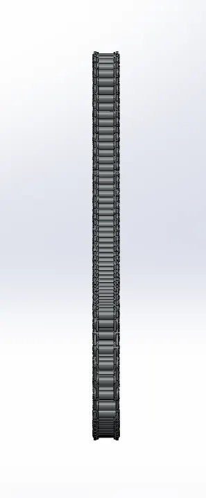
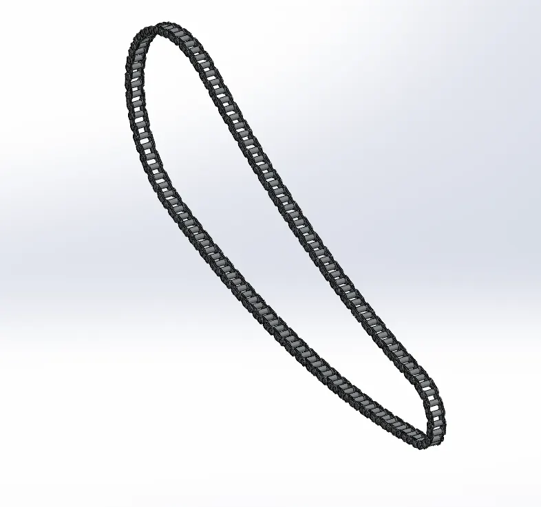
Chain:
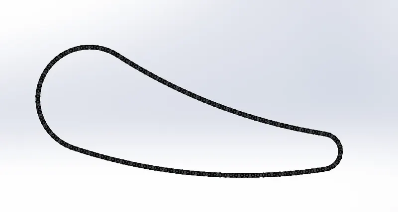
Sketch Commands
- Line
- Slot
- Circle
- Arc
- Trim
- Smart Dimensions
Feature Commands
- Boss Extrude
- Blocks
- Fillet
- Mirror
- Linear pattern
Steps for Modelling Chain:
- A plane is created to sketch the required geometry of lines and arcs of required dimensions using Smart dimensions.
- Two Chain plates are created using Slot, lines and arcs. Saved them as Blocks.
- These Blocks are used to create a sketch with appropriate relations of Concentric and Coincident between them.
- The sketch is extruded using Extrude Boss and the chain plates are made multiple copies using Linear Pattern by using a curve as a reference until the whole geometry is closed.
- Then the Pins which were created as blocks are inserted into the chain plates accordingly.
- Fillet are used to remove the sharp edges.
- Mirror is used to mirror the chain plates.
Front Wheel:
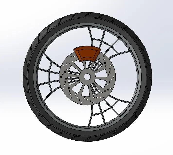
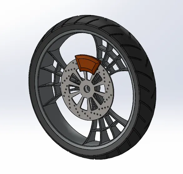
Parts in Front Wheel:
- Rim
- Rotor
- Caliper
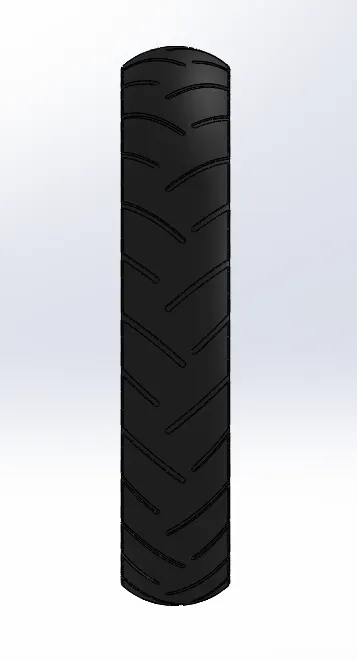
- Tire
Rim
Sketch Commands
- Line
- Arc
- Splines
- Circles
- Mirror
- Offset Entities
- Convert Entities
- Trim
- Fillet
- Smart Dimensions
Feature Commands
- Extrude Boss
- Revolve
- Extrude Cut
- Revolve Cut
- Circular Pattern
- Combine
- Fillet
Steps for Modelling Rim:
- A Plane is selected and required geometries like line and arc is drawn with appropriate dimensions using Smart dimensions.
- This shole sketch is revolved using Revolve Boss feature by selecting an axis.
- The Spokes are drawn with dimensions and by Mirror command required copies are created.
- Extrude Boss is used to add material and Extrude Cut is used to remove material to get the right shape of spokes.
- Circular Pattern is used to increase the spokes around the outer circle.
- Fillet is used to reduce the sharp edges.
Rotor
Sketch Commands
- Line
- Circle
- Smart Dimension
Feature Commands
- Extrude Boss
- Extrude Cut
- Fillet
- Linear Pattern
- Circular Pattern
Steps for Modelling Rotor:
- The required plane is selected and a circle is drawn and extruded suing Extrude Boss.
- Circles are drawn on the face and to increase the number of patterns Linear Pattern is used.
- These circles are removed using Extrude Cut.
- Fillet is used to remove the sharp edges and Chamfer is used at the outer edge of the rotor.
Cailper
Sketch Commands
- Circle
- Trim
- Smart Dimensions
Feature Commands
- Extrude Boss
- Fillet
- Chamfer
Steps for Modelling Caliper:
- Two Circles are drawn on the face of Rotor and then the line are drawn to connect those circles.
- The geometries are extruded using Extrude to add material.
- Chamfer and Fillet are used at the edges for the desired shape.
Tire
Sketch Commands
- Line
- Rectangle
- Arc
- Fillet
- Smart Dimensions
Feature Commands
- Revolve
- Extrude Cut
- Circular Pattern
- Fillet
Steps for Modelling Tire:
- The required sketch is drawn on the plane with fillets at the edges.
- The whole sketch is revolved using Revolve. Rectangles are drawn on the face with required dimensions using Smart dimensions with Fillets at the edges.
- This is removed using Extrude Cut and Circular pattern is used to pattern copies around the axis.
Rear Wheel:
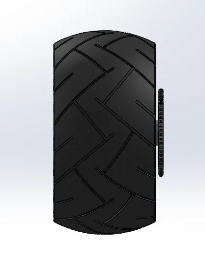
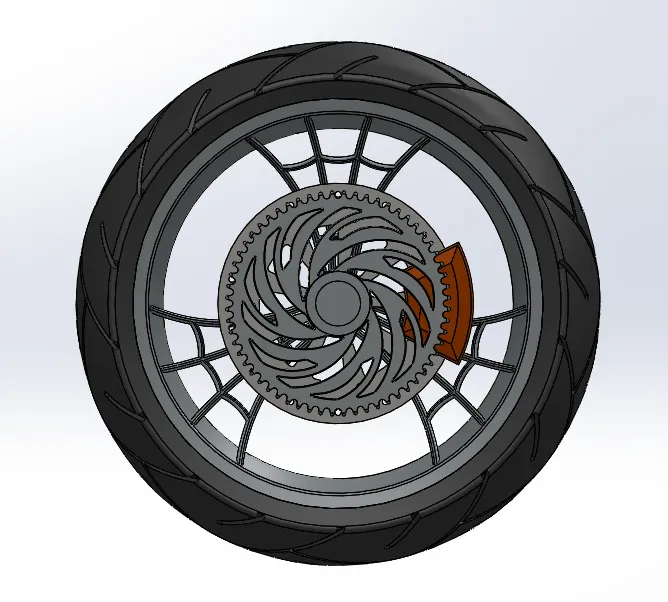
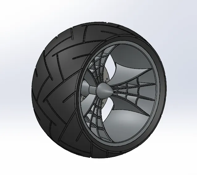
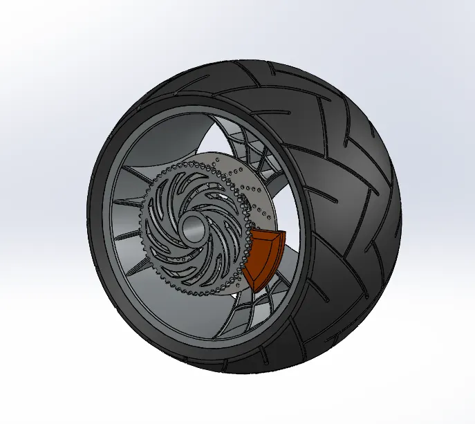
Parts in Rear Wheel:
- Rim
- Rotor
- Caliper
- Sprocket
- Tire
Rim
Sketch Commands
- Line
- Arc
- Splines
- Circle
- Fillet
- Convert Entities
- Mirror
- Offset
- Trim
- Smart Dimensions
Feature Commands
- Extrude Boss
- Extrude Cut
- Revolve
- Circular Pattern
- Revolve Cut
- Combine
- Fillet
Steps for Modelling Rim:
- A required plane is chosen, the sketch with line and arc is drawn with required dimensions
- This sketch is revolved using Revolve by selecting a required axis.
- Plane is selected to draw the spokes and extruded using Extrude Boss to add material. By Using Mirror geometries are copies
- The geometry is removed using Extrude Cut to get the desired shape of the spokes.
- By using Circular Pattern, the spokes are patterned around the outer edge.
- Fillet is used to remove the sharp edges.
Rotor
Sketch Commands
- Line
- Circle
- Smart Dimension
Feature Commands
- Extrude Boss
- Extrude Cut
- Fillet
- Chamfer
- Circular Pattern
- Linear Pattern
Steps for Modelling Rotor:
- A plane is selected and a circle is drawn of required dimension.
- Extrude Boss is used to add Material.
- Circles are drawn of appropriate dimensions and Linear pattern is used to increase the numbers.
- These are removed using Extrude Cut and Circular pattern is sued to increase the copies along the circle.
- Fillet is used to remove the sharp edges.
Caliper
Sketch Commands
- Circle
- .
- Trim
- Smart Dimensions
Feature commands
- Extrude Boss
- Fillet
- Chamfer
Steps for Modelling Caliper:
- Two circles are drawn on the face of the rotor and required lines are used to connect the circles drawn.
- The geometry is extruded using Extrude Boss to add material.
- Fillet and Chamfer are sued to get the desired shape.
Sprocket
Sketch Commands
- Line
- Circle
- Splines
- Trim
- Smart Dimensions
Feature Commands
- Extrude Boss
- Extrude Cut
- Linear pattern
- Circular pattern
- Fillet
Steps for Modelling Sprocket:
- A plane is selected to sketch the geometry with dimensions using Smart Dimensions.
- Circle is extruded using Extrude Boss.
- Splines are drawn and unwanted geometry is trimmed.
- Extrude Cut is used to unwanted material to get the desire shape of Sprocket.
- Circular Patten is used to increase the number of profiles along the circle.
- Fillet is used to remove the sharp edges.
Tire
Sketch Commands
- Line
- Rectangle
- Arc
- Fillet
- Smart Dimension
Feature Commands
- Revolve
- Extrude cut
- Circular Pattern
- Fillet
Steps for Modelling Tire:
- The required sketch is drawn on the plane with fillets at the edges.
- The whole sketch is revolved using Revolve. Rectangles are drawn on the face with required dimensions using Smart dimensions with Fillets at the edges.
- This is removed using Extrude Cut and Circular pattern is used to pattern copies around the axis.
Front Fork:
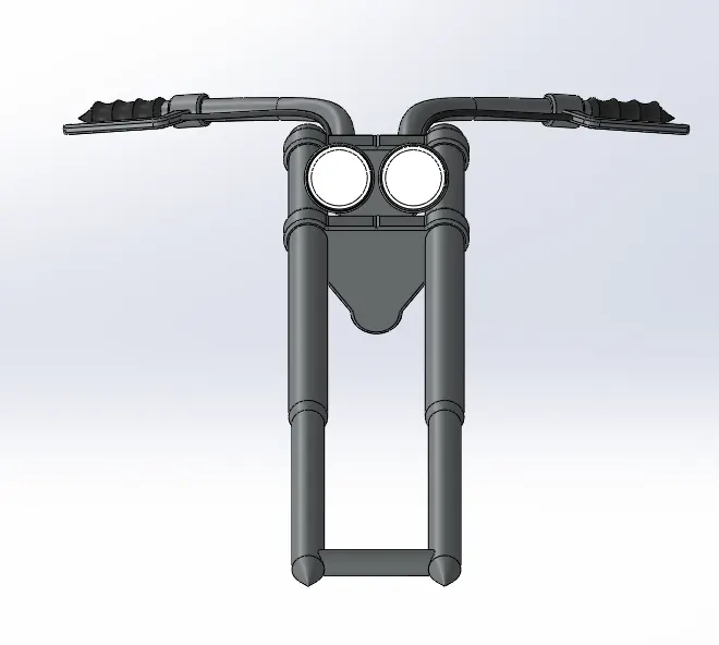
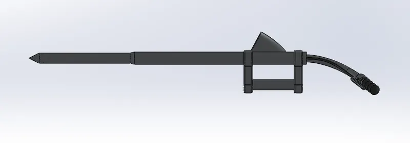
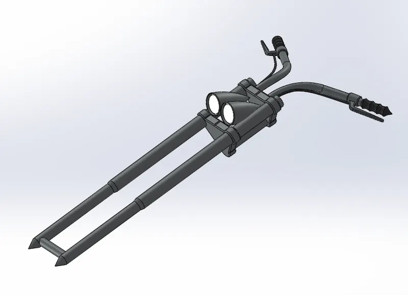
Sketch Commands
- Line
- Circle
- Spline
- Convert Entities
- Trim
- Smart Dimensions
Feature Command
- Extrude Boss
- Revolve Boss
- Extrude Cut
- Linear Pattern
- Dome
- Revolve Cut
- Sweep
- Mirror
- Combine
- Fillet
Steps for Modelling Front Fork:
- A plane is selected to draw a sketch with appropriate dimensions using Smart dimensions.
- The sketch is revolved using Revolve Boss by selecting the required axis.
- At one edge a sketch is drawn and Extrude Boss is sued to add material and Linear Pattern is used to copy the geometry at the required positions.
- At one edge a circle is drawn and extruded to add material. To create head lights, it is revolved using Revolve around an axis.
- Swept Boss is sued to generate the handle. Handle bars are creating by revolving the sketch using Revolve along its base.
- For Brakes required geometry is drawn with appropriate dimensions and extruded to add material.
- Two circles are drawn on different planes and a Spline connecting them. Swept Boss is used to add material along the path to give the geometry of a wire structure.
- Mirror is used to mirror the whole half on its side to complete the entire Front fork Profile.
Chassis:
Sketch Commands
- Line
- Circle
- Arc
- Splines
- Smart Dimensions
- Sketch picture
Feature Commands
- Extrude Boss
- Extrude Cut
- Revolve Boss
- Sweep
- Reference plane
- Mirror
- Fillet
- Chamfer
- Split
- Combine
- Curves
- Dome
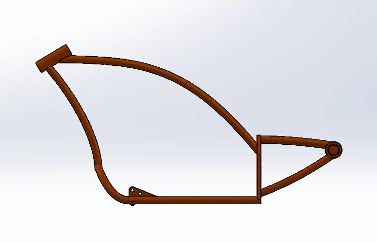
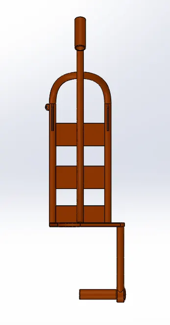
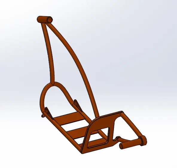
Steps for Modelling Chassis:
- A plane is selected and using Sketch picture command a picture is inserted to SolidWorks. The picture dimensioning and positions is done with required values by double clicking on the picture.
- Using Circle command, the lower edge of chassis is drawn with reference of the inserted picture. Line command is used to connect the concentric circles and projected using Project Curves command with the curves drawn from the top plane with required dimensions using
- By using Swept Boss, the profiles are added with material by following a path. This profile is mirrored to the other side using front plane as reference.
- These two profiles are joined using plates drawn from top plane. Right plane is selected and using lines and circles a geometry is created with relations and extruded using Extrude Boss and to remove Extrude Boss is selected to create plates at the front.
- Fillet and Chamfer are added to the plates. A plane is selected to create a profile for Axle. Circle is drawn and extruded to insert the wheel. A Dome is created on the outer edge.
- To form the Structure of the chassis, Splines are drawn on the front plane with concentric circles to form a good profile. Swept Boss along a path is used to add material and Split tool is used remove material by referring the swept material of tubes.
- In the same way the whole structure of chassis is created with required dimensions using Smart dimensions.
- The chassis is created to form a base for mounting the engine by referring the inserted sketch.
- Fillets are used to remove sharpness at required positions.
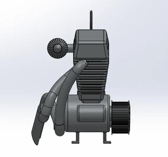
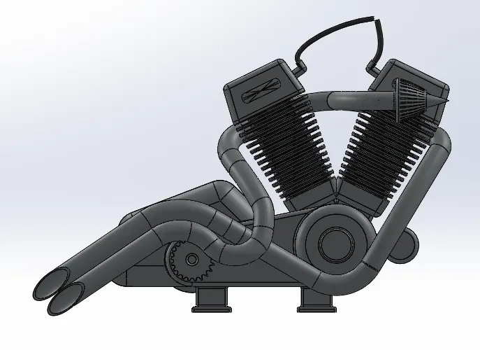
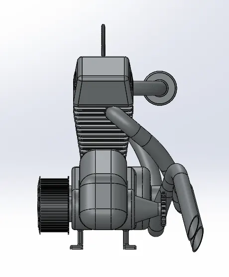
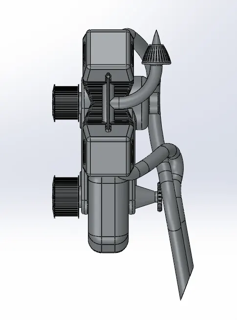
Engine:
Sketch Commands
- Line
- Circle
- Rectangle
- Arc
- Splines
- Sketch picture
- Smart Dimensions
Feature Commands
- Extrude Boss
- Revolve Boss
- Extrude Cut
- Sweep
- Dome
- Split
- Curves
- Chamfer
- Fillet
- Circular Pattern
- Combine
- Mirror
- Reference plane
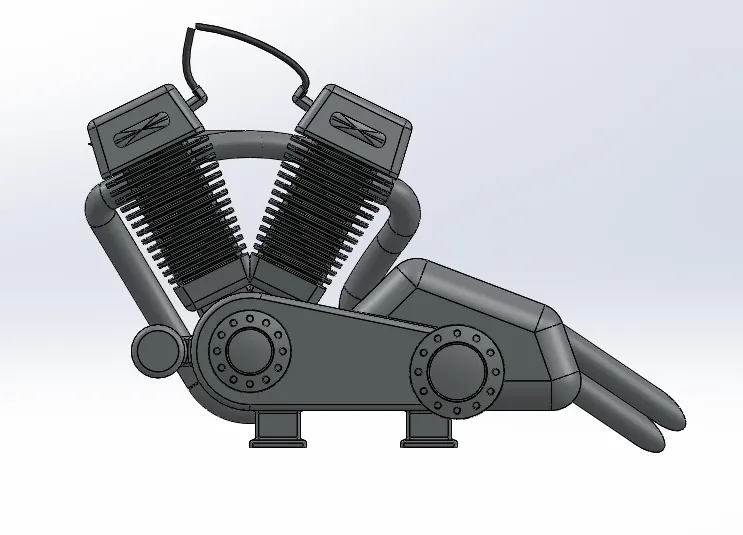
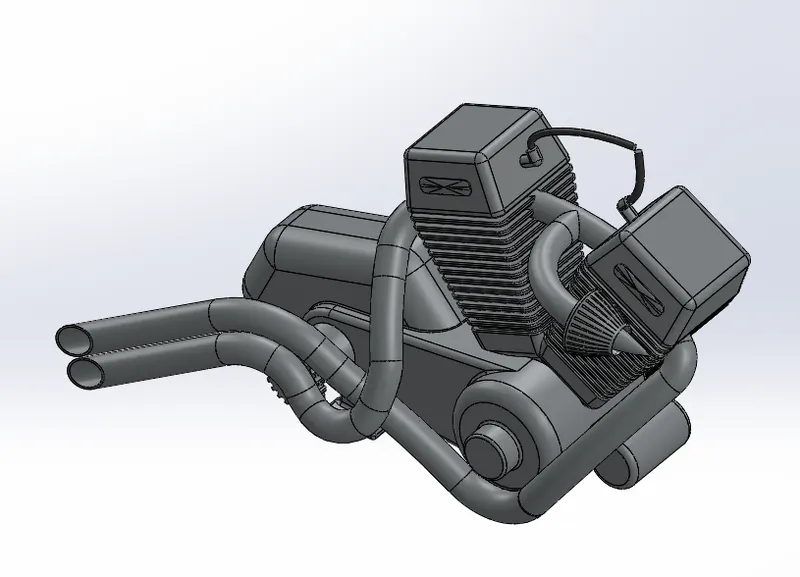
Steps for Modelling Engine:
- A Plane is created to draw the profile and using Sketch Picture a picture is inserted into SolidWorks environment with required geometry.
- By referring the picture, the required geometry is drawn with dimensions and extruded to add material. Circles are drawn and Circular Pattern is used to increase the number of copies to remove material using Extrude Cut. In the same way features are used to match the reference picture.
- Top plane is selected to create the cylinder profile by drawing rectangle and extruding with draft angles with fillets with required positions.
- To create another cylinder, it is mirrored along the front plane. Rectangles are drawn on top of the cylinder of required dimensions and extruded to add material and used Dome and Fillet at corners to create a good profile.
- For Spark plug, a geometry is drawn and swept along a path to add material.
- For exhaust pipes Spines and Arc is used to create the profile in required planes and projected using Curves. This profile path is pierced using pierce relation on a Concentric circle.
- Swept Boss is used to add material along a path and in the same way another exhaust pipe is created. The exhaust tips are cut using Lines for a good profile.
Gas Tank:
Sketch Commands
- Line
- Spline
- Arc
- Trim
- Convert entities
- Offset
- Sketch picture
- Smart Dimensions
Feature Commands
- Reference Commands
- Sweep Cut
- Shell
- Mirror
Surface Commands
- Extrude surface
- Sweep surface
- Loft Surface
- Boundary Surface
- Knit Surfaces
- Projected Curve
- Trim Surface
- Split line
- Fillet
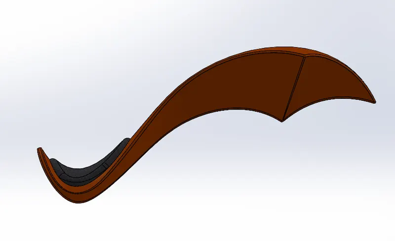
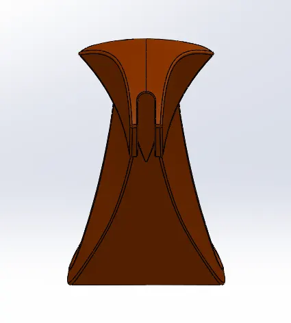
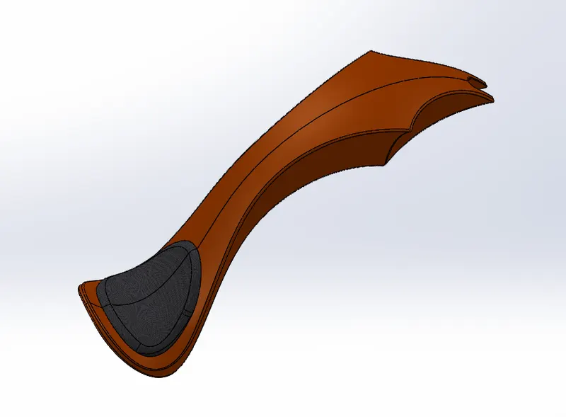
Steps for Modelling Gas Tank:
- A plane is selected for creating geometry. Sketch picture is used to insert a picture to Solidworks
- Spline is used to create the profile of gas tank with required dimensions. By using Reference geometry, a plane is created to draw splines. Swept Surface is used to create a surface along a path
- Loft Surface is used to create surface for required portion by using the plane with required dimensions. Unwanted surface is removed using Trim Surface
- This sketch is selected and projected using projected Curve. The end points are joined using Line by using Pierce Boundary Surface is selected to create surface over it with reference.
- To create the other part of the Gas Tank Mirror is used with plane as reference. Knit is used to combine the two surfaces together
- Seat is created by drawing a profile and by selecting Offset the required shape is created. Extruded using Extrude surface to add material.
- Fillet is used to remove sharpness at the edges.
- Sweep Cut is used to remove the material at requires positions.
- Shell is used to create a hollow surface with thin material of required dimension.
Assembly:

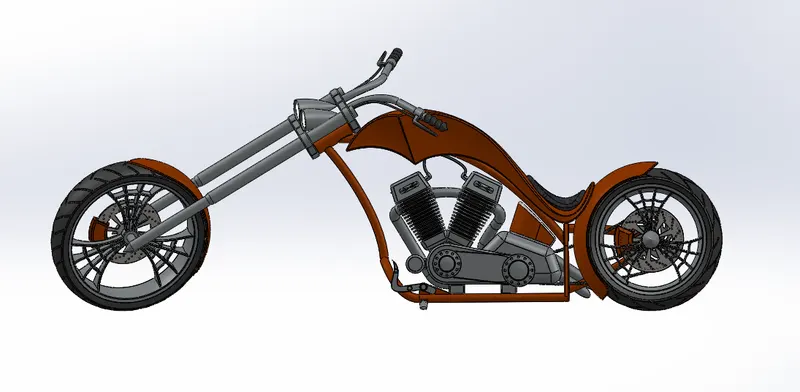
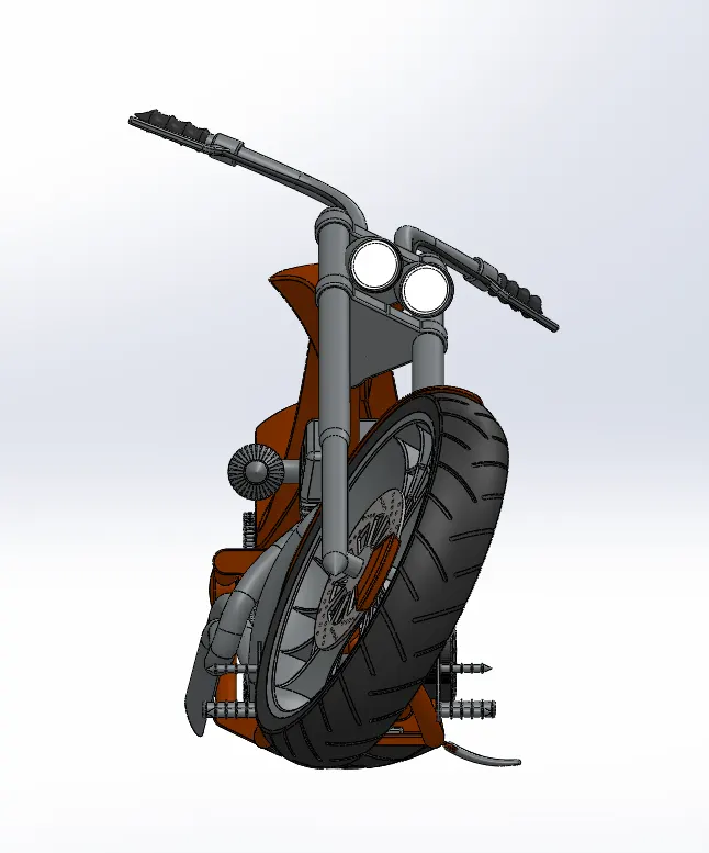
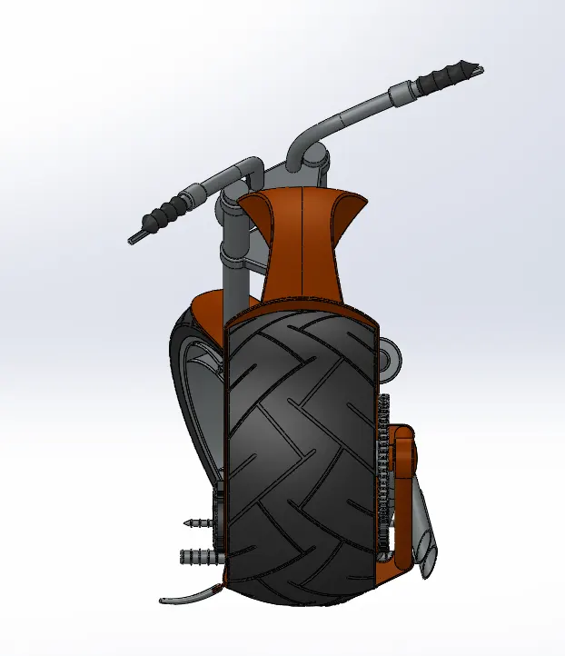
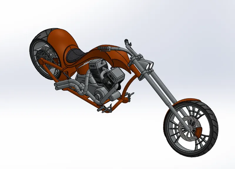
Assembly Commands:
- Insert Component
- Mate
- Mirror Component
Steps for Assembling
- A new assembly file is opened. All parts are selected and opened to be assembled.
- By using Insert Command, Chassis part is selected and placed at the required position
- Engine is inserted and manually placed on the chassis. The bottom planes are selected and made a coincident relation. Both front planes of engine and chassis are selected and given a coincident relation. The front foot face of engine and front face of chassis plate are given a distance relation.
- The Pedal is inserted to assembly and extrude boss of pedal and extrude cut of chassis is selected and given a relation of coincident. The outer surface of pedal and chassis are given a coincident relation. At the end the pedal is mirrored to the other side of chassis to get the required profile.
- The kickstand is inserted to the assembly and the inside surface of kickstand and surface of chassis is given a coincident relation. Bottom plane of both is selected to form coincident relation. The extruded boss of kickstand and extrude cut of chassis are given a coincident relation. For rotation of the kickstand a required angle is given using advanced mate option.
- Transmission belt is inserted and placed at required position. The bigger edge of the belt and extruded part of the engine is selected and given the coincident relation. By using advanced mate option, the width of belt and the extrude cut part are mated together. A required angle is given to the right view with the chassis for the required profile.
- Oil tank is inserted and placed at a required position. The bottom portion of the oil tank and the top portion of the engine is given coincident relation. The midplanes of oil tank and chassis is coincident. The front planes of tank and chassis is coincident.
- Rear wheel is inserted and places in required position. The hub of rear wheel and extruded portion of chassis is selected to form coincident so that th rear wheel are rotate. The midplanes, front planes and right planes are coincident for the required profile.
- Rear fender is inserted and placed in a required position. For the required position on the rear wheel the planes with coincident relations are selected
- Chain is inserted and placed next to the rear wheel. The midplane is coincident with the chassis. By using advanced mates, the width of the chain is mated with the sprocket width and the smaller edge is coincident with the extruded part of the engine for the required profile of the assembly.
- Gas tank is selected and placed top of the engine with mid, front and bottom planes coincident with chassis is formed for the assembly.
- Front fork is selected and placed Infront of the gas tank. By using advanced mate and selecting gas tank and front fork for width selection at required positions the profile for the assembly is formed.
- Front wheel is selected and placed below the front fork. The hub of the wheel and circular profile at the bottom of the fork is selected and coincident using mate option. Required planes re selected and given the coincident relation for a required assembly profile.
- Front fender is selected and placed on the front wheel. For the required position on the front wheel the planes are selected and given coincident relation for the assembly.
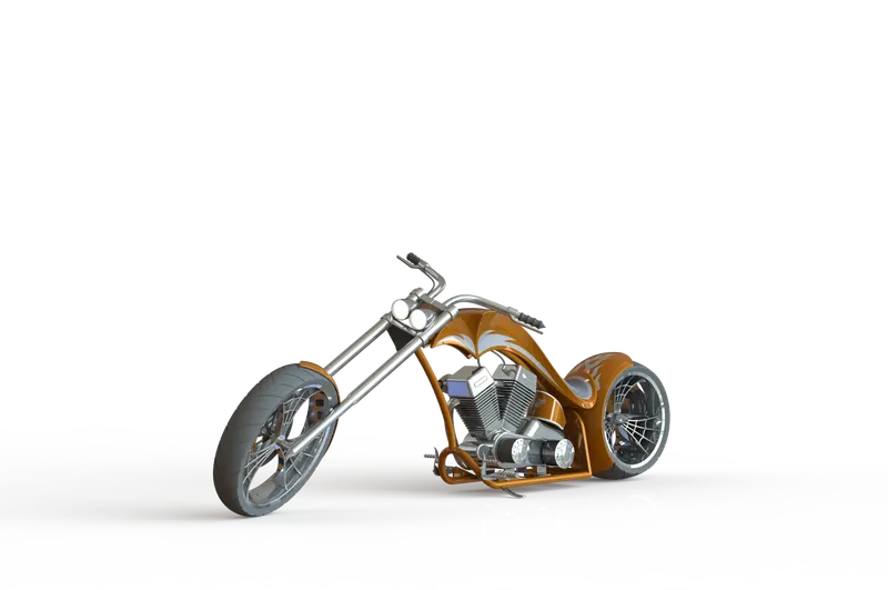
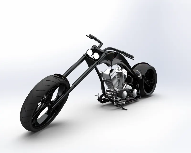
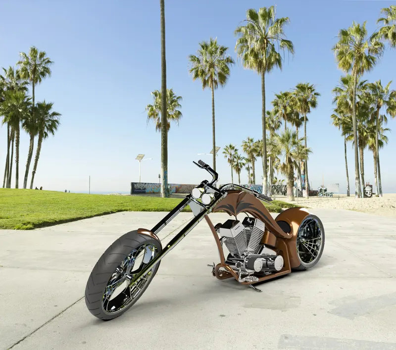
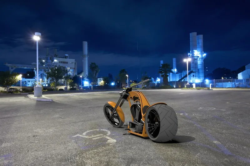
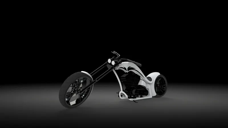
Photorealistic Rendering
Rendering is the process of generating a photorealistic from a 2D or 3D model by means of a computer program. The resulting image is referred to as the render. Multiple models can be defined in a scene file containing objects in a strictly defined language or data structure. The scene file contains geometry, viewpoint, texture, lighting, and shading information describing the virtual scene.
Photoview-360 and SolidWorks Visualize is used to render American Chopper.
Rendered Images:
Conclusion:
- This Project got me vast knowledge about various tools of SolidWorks, designing methods, designing approach and important techniques to ace the 3D modelling.
- Rendering techniques which really helpful to have a complete package of 3D modelling from start to end.