Photo Realistic Rendering
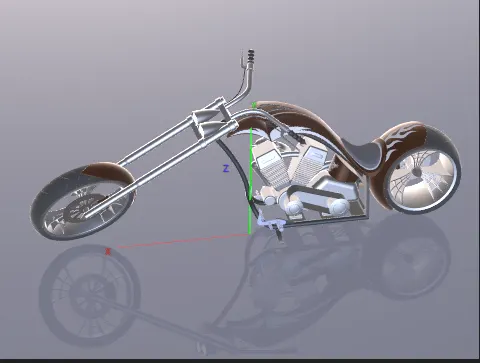
MODELLING OF AMERICAN CHOPPER
INTODUCTION
Orange County Choppers (OCC) bikes are motorcycles featured on the television series American Chopper built by OCC for a specific corporate or celebrity customer. American Chopper is an American reality television series that airs on discovery channel, produced by pilgrim films & television. The series centers on Paul Teutul Sr and his son Paul Teutul Jr who manufacture custom chopper-style motorcycles.
SOFTWARE
SolidWorks was developed by MIT graduate Jon Hirschtick and was bought by Dassault Systems in 1997. The software now encompasses a number of programs that can be used for both 2D and 3D design. It a solid modeling computer-aided design and computer-aided engineering, is one of the most popular software options for mechatronics engineers
OBJECTIVE
- To design individual part of American Chopper in SolidWorks
- To assemble all the parts of American Chopper
- To create a final rendering
FLOWCHART
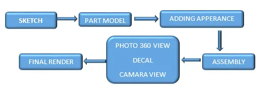
FEATURES USED TO CREATE
- SKETCH
It is used to represent 2D sketch for convertion of 3D model. By using sketch entities like line, circle, fillet, chamfer, trim, mirror etc.
- EXTRUDE BOSS
It is used to convert 2D sketch to solid body, when the sketch is complete closed. We can also convert a line into a solid body by giving thickness.
- EXTRUDE CUT
It is same as extrude boss but it is used to remove material from solid body to get desire model
- LOFT
The loft feature in SolidWorks allows you generate complex geometry in a single feature. It does this by interpolating surfaces between various cross-sections of a model. These cross-sections can be sketches, faces, or edges. In the loft interface, these cross-sections are considered
- LOFT SURFACE
Loft surfaces are surfaces generated by multiple 3D curves or existing edges creating a smooth tangency between the selected curves. Match points are created between each selection denoting the orientation and path of the loft surface
- DOME
It is a curved formation or structure. It is shaped like half of a sphere
- FILLET
Fillet rounds edges at a specified radius. It is used to create sharped edges into round edges. It gives life time to the product by reducing the chances of cracks
- SPLIT
It is used to create multiple parts from an existing part.
- OFFSET
Offset entities takes a copy of your existing geometry, model face or surface and copies it at an offset. Instead of recreating, you can use this to quickly
- APPEARANCE
An appearance defines the visual properties of a model, including color and texture. Appearances do not affect physical properties, which are defined by materials. Every material is assigned a default appearance that emulates the look of the material contents
- TRIM
The Trim tool is mainly used for removing unwanted parts or portions from your design
- REVOLVE
Revolves add or remove material by revolving one or more profiles around a centerline. You can create revolved boss/bases, revolved cuts, or revolved surfaces. The revolve feature can be a solid, a thin feature, or a surface
- DYNAMIC MIRROR
Select the dynamic mirror entities tool to first select the entity about which to mirror, and then sketch the entities to mirror
- PATTERNS
Pattern tool allows you to create patterns along the line or curve. To define the pattern, you can use any sketch segment, or the edge of a face (solid or surface), that lies along the plane. You can base your pattern on an open curve, or on a closed curve, such as a circle.
- COMBINE
The common function allows you to add two bodies together, and keep the area that is common to them
- SHELL
The shell tool hollows out a part, leaves open the faces you select, and creates thin-walled features on the remaining faces
- CHAMFER
The chamfer tool creates a beveled feature on selected edges, faces, or a vertex
- PLANE
It helps to design a sketch in a distance, angle from the origin
- MOVE/COPY BODIES
It is useful when a part is needed to be shown in multiple configurations. It takes a body, copies it, and moves it to the desired location
- PROJECT CURVE
A sketch projected to a model face or surface, or from sketched lines on intersecting planes
- COMPOSITE CURVE
It helps to convert two different lines into a single line and also help to join the broken curves
- SWEEP
It creates a base, boss, cut, or surface by moving a profile (section) along a path, according to these rules: The profile must be closed for a base or boss sweep feature; the profile may be open or closed for a surface sweep feature. The path may be open or closed.
- CONVERT ENTITIES
It allows users to make a copied projection of a given sketch, face, or set of edges onto the active sketch plane
DESIGN OF INDIVIDUAL PARTS OF CHOPPER
FRONT FENRDER
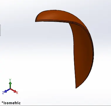 |
FEATURES · Sketch · Offset Entities · Trim · Revolve · Dynamic Mirror · Split · Appearance |
KICK STAND
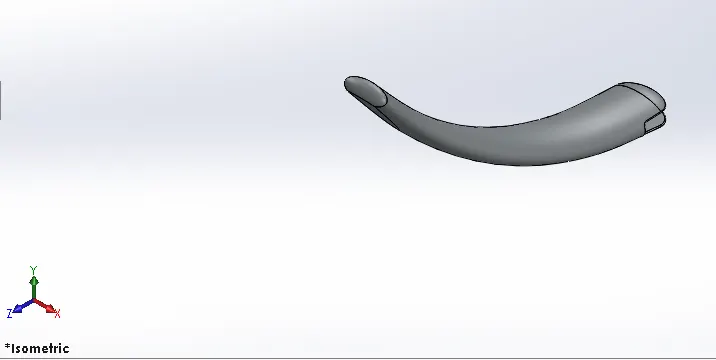 |
FEATURES · Sketch · Loft · Dome · Extrude Boss · Extrude Cut · Split · Fillet |
REAR FENDER
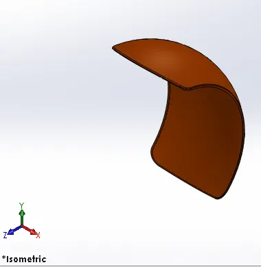 |
FEATURES · Sketch · Offset Entities · Trim Entities · Appearance · Revolve |
TRANSMISSION BELT
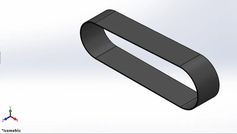 |
FEATURES · Sketch · Offset · Fillet · Appearance · Extrude |
CHAIN
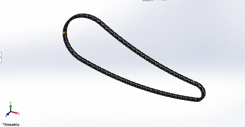 |
FEATURES · Sketch · Fillets · Blocks · Trim · Extrude · Patterns · Appearance |
OIL TANK
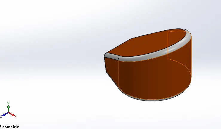 |
FEATURES · Sketch · Extrude · Fillets · Shell · Combine |
PEDAL
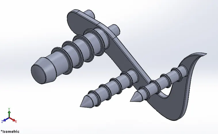 |
FEATURES · Sketch · Fillet · Extrude · Linear Pattern · Dome · Chamfer |
FRONT WHEEL
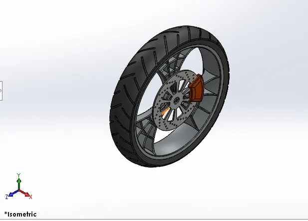 |
FEATURES · Sketch · Revolve Cut · Fillet · Extrude · Extrude Cut · Chamfer · Circular Pattern · Linear Pattern |
FRONT FORK
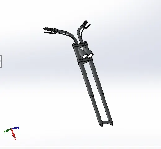 |
FEATURES · Sketch · Revolve · Extrude · Trim · Sweep · Move/Copy Bodies · Dome · Mirror · Combine · Project Curve · Split |
REAR WHEEL
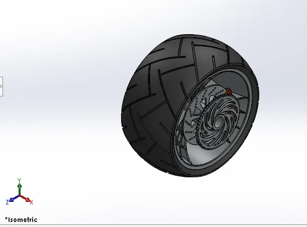 |
FEATURES · Sketch · Revolve · Trim · Extrude Boss · Extrude Cut · Circular Pattern · Fillet · Planes · Revolve Cut · Chamfer · Linear Pattern |
CHASIS
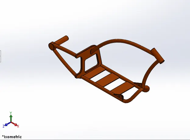 |
FEARTURES · Sketch · Offset · Convert Entities · Trim · Project Curve · Sweep · Split · Revolve · Extrude Cut · Fillet · Combine |
ENGINE
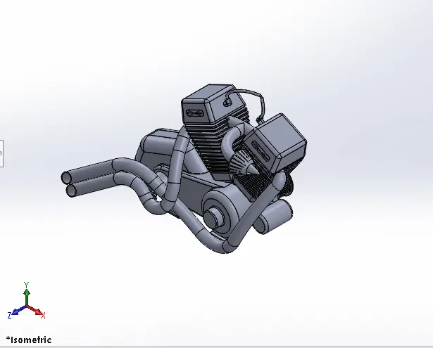 |
Features · Sketch · Trim · Revolve · Extrude Boss · Extrude Cut · Offset · Fillet · Dome · Project Curve · Composite Curve · Sweep · Mirror · Circular Pattern · Split |
GAS TANK
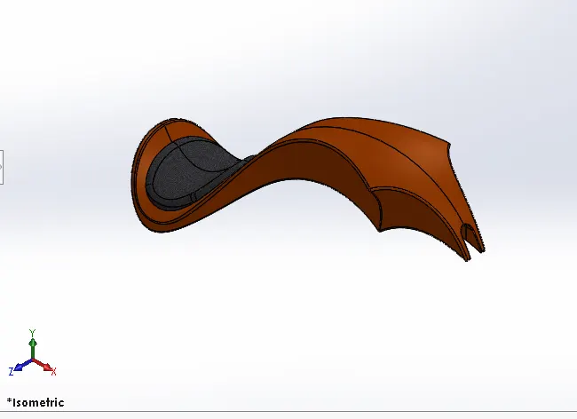 |
FEATURES · Sketch · Trim · Sweep Cut · Projected Curve · Loft Surface · Fill Surface · Sweep Surface · Fillet · Surface Trim · Surface Knit |
ASSEMBLY
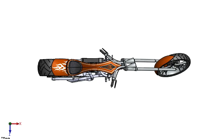
TOP VIEW
SIDE VIEW
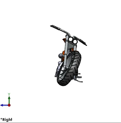
FRONT VIEW
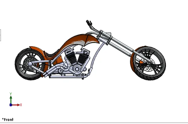
ISOMETRIC VIEW
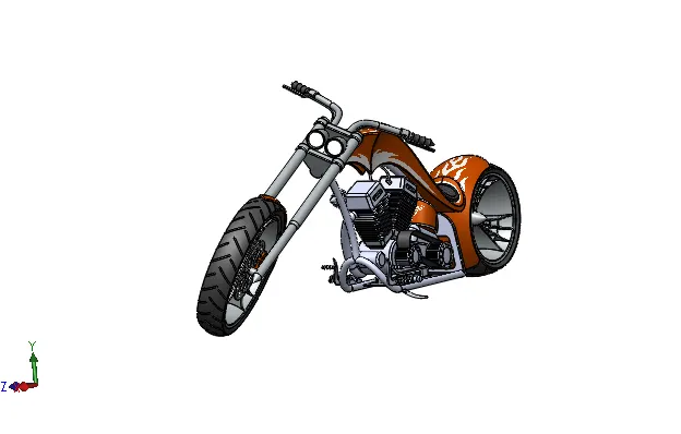
CAMERA SETUP VIEW
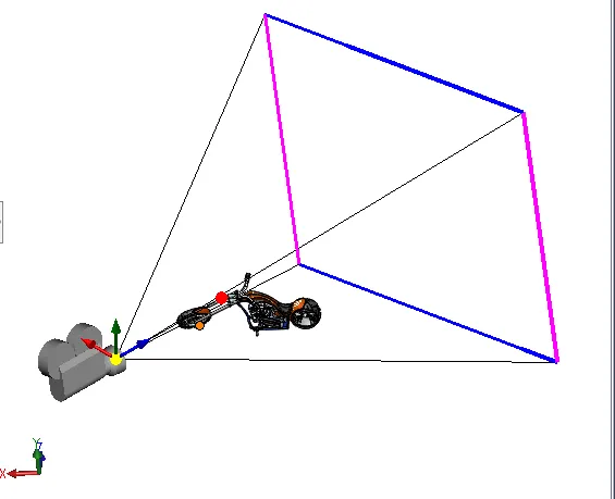 |
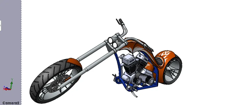 |
FEATURES
- MATE
Mates create geometric relationships between assembly components. As you add mates, you define the allowable directions of linear or rotational motion of the components. You can move a component within its degrees of freedom, visualizing the assembly's behavior.
- PHOTO VIEW 360
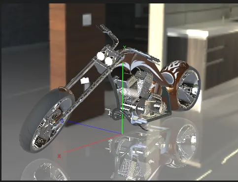
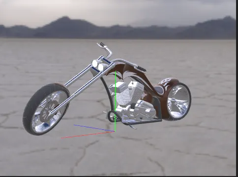
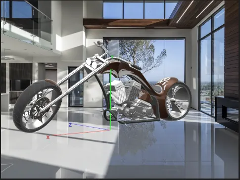
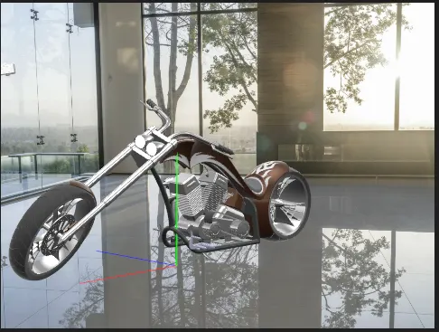
Photo View 360 is a SolidWorks add-in that produces photo-realistic renderings of SolidWorks models. The rendered image incorporates the appearances, lighting, scene, and decals included with the model.
RENDER IMAGE – 1
RENDER IMAGE – 2
RENDER IMAGE – 3
RENDER IMAGE – 4
RENDER IMAGE – 5
CONCLUSION
- The parts of American Chopper are modelled
- Assembly all the individual parts to acquire the Chopper.
- Create final render realistic view by using Photo iew 360