Photo Realistic Rendering
American Chopper
Objective: To design, assemble and render the American Chopper using Solidworks
Introduction: The name” American Chopper” is taken from an American reality television series, produced by Pilgrim Films & Television. In 1969 the movie "Easy Rider" was released which brought the Chopper into the public eye.
The chopper consists of following parts. These parts are modelled using Solidworks.
1.Transmission Belt
2.Kick Stand
3.Front Fender
4.Rear Fender
5.Oil Tank
6.Chain
7.Pedal
8.Front Wheel
9.Rear Wheel
10.Front Fork
11.Engine
12.Chassis
13.Gas Tank
Transmission Belt
Transmission belt is used to transmit power from engine to Gearbox.
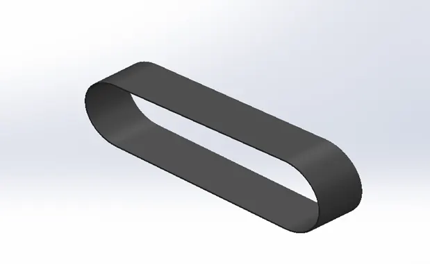
Features used to create the Transmission Belt.
- Sketch
- Offset
- Extrude
- Fillet
- Appearances
- Sketch: Sketch is the two-dimensional representation of model on any plane (Front Plane, Top Plane, Bottom Plane, etc.). Different Sketch entities tools are used in Solid works Such as Line, Spline, Arc etc.
- Offset: It is used to offset one or more sketch For Instance, we canoffset sketch entities such as splines or arcs, sets of model edges and so on.
- Extrude: Basically, It Converts any 2D sketch into 3D model.
- Fillet: It creates rounded internal or external faces on the part. We canfilletall edges of a face, selected sets of faces, selected edges.
- Appearances: Every material is assigned a defaultappearance that emulates the look of the material. It is visual properties of a model, including colour and texture.
Kick Stand
Kick Stand is a Component which Supports the Motorcycle when not in use. Essentially, it is attached with Chassis of Motorcycle.
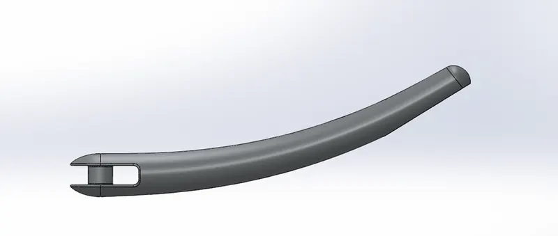
Features used to create the Kick Stand.
- Sketch
- Loft
- Dome
- Extrude cut.
- Extrude Boss
- Split
- Fillet
- Appearance
- Loft: It allows us to create Complex Geometry. Loftcreates a feature by making transitions between profiles. Aloft can be a base, boss, cut, or surface.
- Dome: It works as Fillet feature, but the only difference is that it is applied irregular shape Contours.
- Split: It is used to cut extra solid bodies. It is very powerful tool to cut and consume any unwanted solid bodies.
- Fillet: At the end, Fillet was applied to gain round edges.
Front Fender
Front Fender is a Component provided to protect rider and the chopper parts from Dust or any foreign particles.
Features used to create the Front Fender.
- Sketch
- Offset Entities
- Trim Entities
- Revolve
- Dynamic Mirror
- Split
- Trim Entities is used to extend or trim the extra sketches. It is available in 2D sketches.
- Revolve Create a sketch that contains one or more profiles and a centreline, line, or edge to use as the axis around which the featurerevolves.
- Dynamic Mirror Entity works by automating themirrorentities tool while you are sketching. When this tool is activated.
Rear Fender
Rear Fender works as Front Fender. It is mounted on Rear wheel behind the chassis.
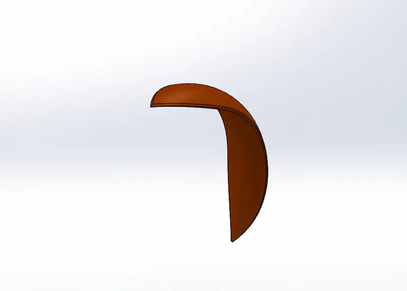
Features used to create the Rear Fender.
- Sketch
- Offset Entities
- Trim Entities
- Revolve
- Appearance
Oil Tank
Oil Tank is a Hollow part of the Chopper. It is mainly used to store oil to run the Engine.
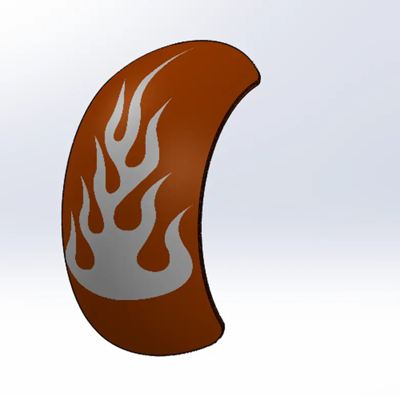
Features used to create the Oil Tank.
- Sketch
- Boss Extrude
- Combine
- Shell
- Fillet
- Appearances
- Combine: This feature helps to combine two Solid bodies.
- Shell: It creates a certain thickness in hollow part.
Chain
Chain is a basic element of Transmission system. It transmits power from engine to the rear wheel. It is connected to engine and Rear wheel by means of sprocket.
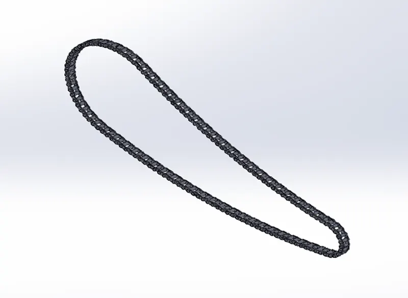
Feature used to create the Chain.
- Sketch
- Offset Entities
- Trim Entities
- Revolve
- Block
- Curve Driven Pattern
- Appearance
- Curve Driven Pattern tool allows you to createpatternsalong a planar or 3D curve. To define the pattern, you can use any sketch segment, or the edge of a face (solid or surface), that lies along the plane. You can base your pattern on an open curve, or on a closed curve, such as a circle.
- Block: Sketching Blocks provide a simple, but powerful method of grouping objects.
Procedure to generate a block:
- Create a sketch.
- Click Make (Blocks toolbar) or Tools > Block > Make. ...
- Select the sketch entities you want to make as ablock for Block
- Repeat steps 2-4 for each of the remaining sketch entities.
- With the sketch in edit mode, add the necessary relations.
- Save the part.
Pedal
Pedal is attached to the Chassis where rider puts his leg.
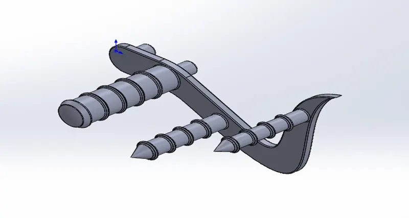
Features used to create the Pedal.
- Sketch
- Boss Extrude
- Linear Pattern
- Chamfer
- Fillet
- Dome
- Appearances
- Chamfer tool creates slightly slopeon selected edges, faces, or a vertex.
- Linear Pattern is like Circular pattern. But creates the solid bodies linearly.
Front Wheel
Front wheel is made up of Alloy. Tyre is embedded on top of it which is made up of rubber material. The main function is to covert rotational motion into linear.
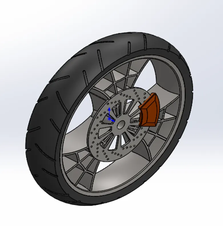
Features used to create the Front wheel.
- Sketch
- Revolve
- Trim
- Boss Extrude
- Linear Pattern
- Revolve Cut
- Cut Extrude
- Circular Pattern
- Fillet Feature
- Appearances
- Circular pattern: To create grips on tyre. It is also used to produce holes on rotor.
- Fillet Feature is primarily used to generate round edges.
Rear Wheel
It is another circular component of chopper located rear of chassis. Sprocket of wheel is connected to engine through Chain.
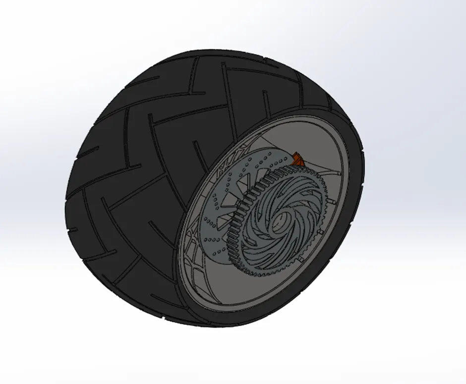
Features used to create the Rear wheel.
- Sketch
- Revolve
- Trim
- Boss Extrude
- Linear Pattern
- Revolve Cut
- Cut Extrude
- Circular Pattern
- Fillet Feature
- Appearances
Front Fork
Front Fork is a kind of Shock absorber. It absorbs most of vibration caused by uneven roads and let motorcycle move forward without any disturbance.
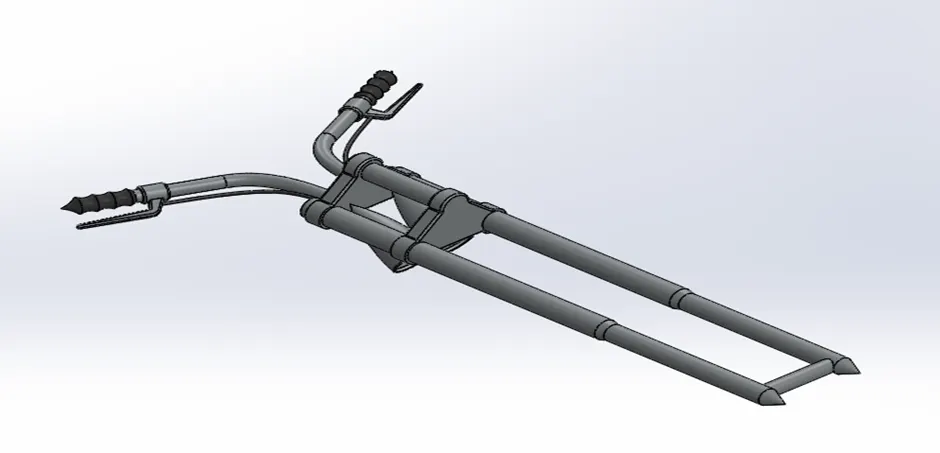
Features used to create the Rear wheel.
- Sketch
- Revolve
- Trim
- Boss Extrude
- Convert Entities
- Mirror
- Cut Extrude
- Split
- Fillet Feature
- Combine
- Move/Copy Body
- Appearances
- Move/Copy Body is used when a part is needed to be shown in multiple configurations, such as a clamp or a door.
- Mirror: Here, it used to mirror half part of the fork. To use mirror, feature an appropriate plane must be drawn.
Engine
Engine helps to convert Chemical energy into heat energy and further heat energy is Converted into Mechanical energy by means of Chain and Sprocket Mechanism.
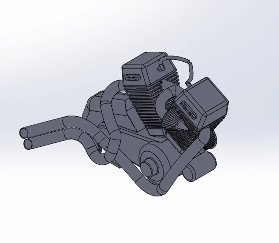
Features used to create the Rear wheel.
- Sketch
- Revolve
- Trim
- Boss Extrude
- Convert Entities
- Mirror
- Cut Extrude
- Split
- Fillet Feature
- Combine
- Move/Copy Body
- Appearances
Chassis
It is said to be Skeleton of the Motorcycle. All the Components are mounted on the chassis such as Engine, pedal and Kick Stand and so on.
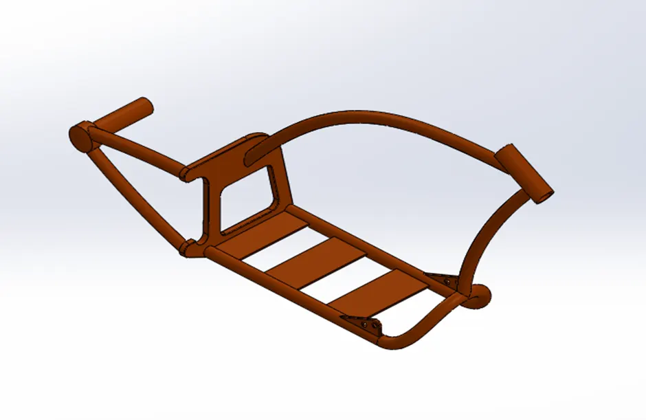
Features used to create the Chassis.
- Sketch
- Revolve
- Trim
- Boss Extrude
- Convert Entities
- Mirror
- Cut Extrude
- Split
- Fillet Feature
- Combine
- Move/Copy Body
- Appearances
Gas Tank
Gas tank is mounted on the chassis whose primary function is to store the gas.
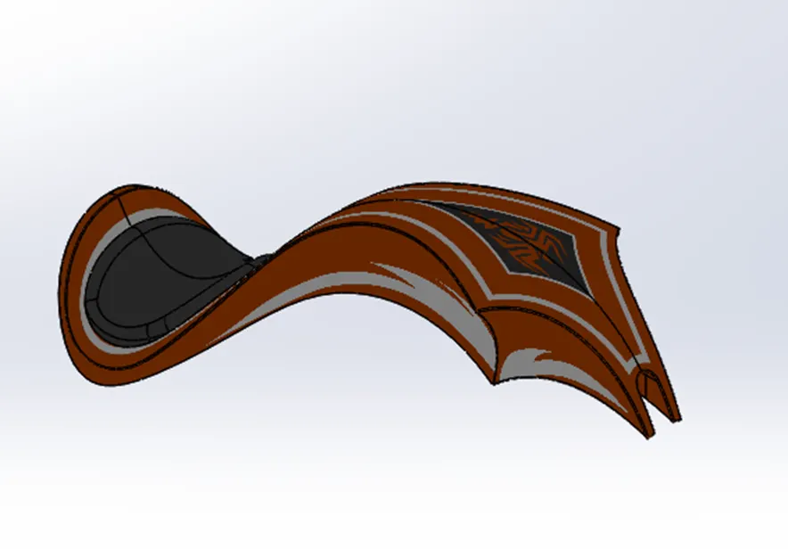
Features used to create the Gas Tank.
- Sketch
- Trim
- Projected Curve
- Sweep Surface
- Surface Trim
- Boundary Surface
- Mirror
- Surface knit
- Split line
- Surface Extrude
- Surface Knit
- Projected Curve You canprojecta sketched curve onto a model face to create a 3D
- Sweep Surface is thesurfacegenerated by moving curve.
- Surface Trim is Primarily used to cut away material from asurface,
- Surface knit is Used to combine two or more faces andsurfacesinto one.
Assembly of chopper
- First and foremost, Chassis is inserted in Assembly and made fix with Front Pane of Assembly. Then all the Components was inserted and applied mate with respect to Chassis.
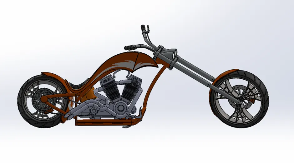
Feature used to assemble the Chopper.
- Mates
- Advanced Mates
- Mechanical Mates
- Insert part.
Mate tool is used for joining parts in an assembly to simulate how they fit and move together. It generates geometric relation between the components.
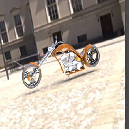
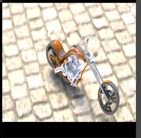
Photo Realistic Rendering.
- Rendering the process of creating realistic images.
- Mainly, Rendering is done two ways. They are:
- Photoview 360.
- Solidworks Visualize.
Some of Rendered images are listed below:
Conclusion:
- The chopper parts are modelled using Solidworks.
- All the Components are Assembled in Solidworks Assembly.
- The realistic images were generated using Photoview 360.