Photo Realistic Rendering
https://drive.google.com/drive/folders/1-SI4OxPqHXYpFS4mBsmAfJsKpUw86XLv?usp=sharing
Project Report
American Chopper
AIM
To achieve knowledge on solid, surface modelling and assembly, rendering tools by modelling a photorealistic American chopper using solid works and photoview 360.
OBJECTIVE
To build all the parts of an American chopper by using solid and surface modelling tools and to assemble the multiple parts into a single chopper by assembling and rendering them more realistic by using photoview 360.
Components of chopper
- Chassis
- Engine
- Transmission belt
- Chain
- Pedal
- Kickstand
- Front fork
- Front fender
- Front wheel
- Rear fender
- Real wheel
- Oil tank
- Gas tank
Procedure
Chassis
The chassis is the back bone of the chopper in which all the components are mounted. It is a load bearing structure for the vehicle. This model acts as the base component for the assembly.
Tools used
- Curve
- Sweep
- Mirror
- Extrude
- Cut Extrude
- Chamfer
- Fillet
- Split
- Combine
- Mirror
Rendered model
CAD model
Engine
Engine is the power house of the chopper. It is a device used to convert chemical energy into mechanical energy and which provides power for the movement of vehicle.
Tools used
- Extrude
- Fillet
- Revolve
- Circular Pattern
- Dome
- Chamfer
- Fillet
- Mirror
- Split
- Sweep
- Composite Curve
Rendered model
CAD model
Transmission belt
Transmission belt is used to transmit power from engine to gearbox.
Tools used
- Fillet
- Extrude
Rendered model
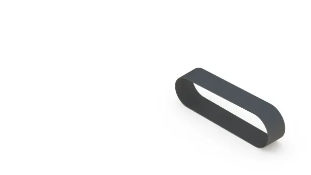
CAD model
Chain
Chain drive is a way of transmitting mechanical power from one place to another and it is used to convey power to the wheels of a vehicle.
Tools used
- Extrude
- Fillet
- Curve driven pattern
- Mirror
Rendered model
CAD model
Pedal
Pedals are mounted on the external side of the chassis and it also acts as a footrest for the rider.
Tools used
- Spline
- Extrude
- Extrude Cut
- Mirror
- Dome
- Chamfer
Rendered model
CAD model
Kickstand
Kickstand is mounted on the chassis and used to support the chopper when not in motion.
Tools used
- Spline
- Loft
- Split
- Extrude
- Cut Extrude
- Dome
Rendered model
CAD model
Front fork
Front fork connects the chassis and the front wheel of the chopper and it also provides the driving mechanism for the chopper.
Tools used
- Revolve
- Extrude
- Fillet
- Linear Pattern
- Dome
- Cut Revolve
- Fillet
- Combine
Rendered model
CAD model
Front fender
Its primary purpose is to prevent sand, mud, rocks, liquids, and other road spray from being thrown into the air by the rotating tire.
Tools used:
- Spline
- Fillet
- Extrude
- Split
- Revolve
Rendered model
CAD model
Rear fender
Its primary purpose is to prevent sand, mud, rocks, liquids, and other road spray from being thrown into the air by the rotating tire.
Tools used
- Spline
- Fillet
- Extrude
- Split
- Revolve
Rendered model
CAD model
Front wheel
Front wheel helps the rider to steer the vehicle in their required direction and it stabilize the chopper with the road and also helps in moving the vehicle
Tools used
- Revolve
- Extrude
- Cut Extrude
- Circular Pattern
- Chamfer
- Fillet
- Combine
Rendered model
CAD model
Rear wheel
The output power from the gear box is transmitted to the rear wheel and it holds the entire weight of the chopper and provides the movement to the vehicle.
Tools used
- Revolve
- Extrude
- Cut Extrude
- Circular Pattern
- Chamfer
- Fillet
- Combine
Rendered model
CAD model
Oil tank
Oil tank is to store the oil for lubrication and pumped to the engine.
Tools used
- Spline
- Fillet
- Extrude
- Combine
- Shell
Rendered model
CAD model
Gas tank
The main purpose of gas tank is to store the fuel for the engine and pumping to the engine at the time of lubrication.
Tools used
- Surface Sweep
- Surface Trim
- Surface Loft
- Boundary Surface
- Surface Knit
- Sweep cut
- Fillet
- Mirror
- Shell
Rendered model
CAD model
Assembly of chopper
Every individual modelled part of the America chopper is successfully designed and the parts are assembled with each other in a proper way to describe the structure of chopper using solidworks assembly feature.
Tools used:
- Mid plane mate
- Tangent mate
- Coincident
- Parallel
- Perpendicular
- Distance mate
- Angle mate
- Concentric
- Width mate
- Mirroring of pedal
Rendering of chopper
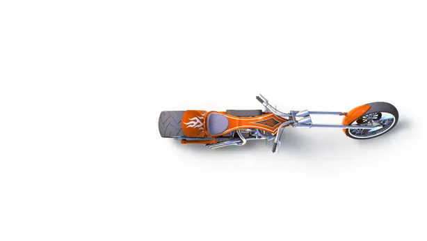
Rendering is used to convert the cad model appearance into a photorealistic view using photoview 360 feature in solidworks by adding the lights, camera, decals etc. The rendering has been done for the chopper and the output is given below.
Tools used:
- Edit appearance
- Edit scene
- Edit decal
- Integrated preview
- Preview window
- Final render
- Schedule render
- Camera
- Light
FRONT OF CHOPPER VIEW
RIGHTSIDE VIEW
FRONT VIEW
LEFTSIDE VIEW
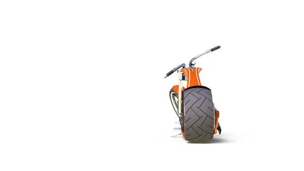
ISOMETRIC VIEW
CAMERA SETUP VIEW
TOP VIEW
Conclusion
The modelling of every individual part of the chopper is completed and assembled in solidworks and also the rendered photorealistic view is given for the chopper using photoview 360.