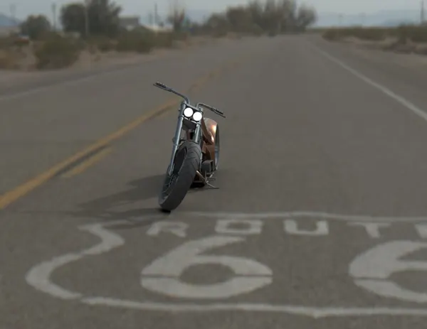
Photo Realistic Rendering
Objective
The main objective of this project is to model American chopper from scratch by assembly of various components. These documents highlight the methods used in sketching and modelling the various components. Below are the part objects in the assembly model of the chopper.
- Transmission belt
- Kick Stand
- Front Fender
- Rear fender
- Oil tank
- Pedal
- Front Wheel.
- Rear Wheel.
- Front Fork.
- Gas tank.
Upon completion of all the part models then the final Assembly is done. Rendering of the entire assembly is done using SOLIDWORS visualize. We will talk about each component in detail in the coming sections.
Transmission belt
Transmission belts are used for power transmission from engine camshaft to the gear assembly. In this chopper design the transmission belt is used from the engine camshaft to the gear assembly. The rotary motion is then transferred to the rear wheel using a chain. Transmission belt is made of special neoprene material. For creation of the transmission belt the sketch is made in one plane, corresponding offset is made to incorporate the thickness of the belt and then the whole sketch is extruded out to 88 mm. below steps are used
- Sketching
- Use of sketching constraints (tangent, coincident constraints)
- Smart dimensioning
- Use of offset tool to offset the figure externally by 3.5 mm
- The extrude by 88.00 mm
- Fillet of 1mm on the side edging externally only.
Features used in making this model is
- Sketch
- Offset
- Extrude
- Fillet
- Appearances
Kickstand
The kick stand is used to support the chopper onto the ground. Made of stainless steel and chrome plated this part is made using the below feature.
- Sketch
- Loft
- Dome
- Extrude Boss
- Extrude cut
- Fillet
- Split
- Appearances
Before creating the sketch, the default plane names are changed as given below,
- Front Plane - Front Plane
- Top Plane - Top Plane
- Right Plane - Mid Plane
Then, the mid plane is selected to sketch. The 2D sketch is created in the front plane and dimensions, relations are given to the sketch to fully define a sketch. While sketching we used the spline and trim commands are used. There are two new planes created and the ellipse are drawn in the new plane as per the requirement. Then the loft command is used to create a loft for the Kickstand. The extrude cut command is used to cut the parts which are not required for the stand. Below is the rendered image of the kickstand.
Kickstand
Front fender
The front fender is a guard which protects the rider from the dirt and other particles which comes form the fast-rotating tire and is for the safety of the rider. The features used for making this model are
- Sketch
- Offset entities
- Trim entities
- Revolve
- Dynamic mirror
- Split
- Appearances
The sketch is drawn on a plane and then offset to give the required thickness. Then the excess entities are trimmed off and then revolved around an axis in bottom plane. The revolve is done with angular values at both directions. Then to give final shape we draw a spline with dynamic mirror on both edges of the unfished fender. The excess parts are then trimmed off using the split feature. Final stages are providing the appearance for the fender.
Front Fender
Rear fender
To protect the rider from the dirt and particles and for safety the rear fender is provided. The features used in the rear fender is
- Sketch
- Offset Entities
- Trim Entities
- Revolve
- Appearance
Decals are also provided in this fender.
Oil Tank
Oil tank stores the oil which is required to run the engine. The oil tank is hollow with 3 mm thickness. Below are the features used to model the oil tank.
- Sketch
- Boss Extrude
- Combine
- Fillet
- Shell
- Appearances
The initial sketch is made in on bottom plane and extruded. Then another sketch is made and extruded. Both these bodies are then combined and the common part is selected to make the oil tank. Then the edges are fillet and then give adequate appearances. Below is the oil tank rendered image
Oil tank
Chain
The chain is used to transmit the rotary motion of the gear box to the rear wheel. The chains are resting inside the sprocket where one is attached to the gear box and the other is attached to the rear wheel. Below are features which are used to model the chain
- Sketch
- Trim
- Fillet
- Blocks
- Extrude
- Patterns
- Appearances
In this model we have used Blocks where we can make a sketch and save it and it is used multiple times. Each chain link and pin is sketched as a block , Initially a path is sketched for these blocks of links and we use curved and circular pattern to take it along the curved path.
Chain
Pedal
The pedal is used as a foot rest for the rider and is on both the sides of the chopper. Below are the features used for modelling of the pedal.
- Sketch
- Extrude
- Fillet
- Linear pattern
- Dome
- Chamfer
- Appearances
The circular rings are made along the cylindrical rods to give grip and these are modelled using linear patterns.
Pedal
Front wheel and rear wheel
Both the front and rear wheel are circular with the rear wheel being wider than the front wheel. These have spider web designs and have both have disc and calliper braking system. The rear wheel also has a sprocket. The below features are used to model the front and rear wheel.
- Sketch
- Revolve
- Trim
- Fillet Entities
- Boss/Base Extrude
- Revolve Cut
- Linear pattern
- Chamfer
- Fillet Features
- Cut Extrude
- Circular Pattern
- Appearances
The circular pattern is used to create the spider web design, where initial pattern is made first and then rotated. The sprocket is also made initially using a circular extrude and then cut extrude of the groves with a circular pattern around the disc.
Front wheel
Rear wheel
Chassis
The chassis or the frame forms the main frame/Skelton of the chopper. It houses the engine, fuel tank and is connected to the front fork and other parts. This is the base structure for attaching all the parts to form the final chopper. Below is the feature used to create the chassis.
- Sketch
- Offset
- Convert entities
- Project Curve
- Trim
- Plane
- Sweep
- Split
- Revolve
- Cut Extrude
- Fillet
- Combine
- Appearance
Chassis
Engine
The engine is modelled as single unit with 2 combustion chambers protruding outside with air fins to cool the engine. The cam shaft and the gear train are located downwards towards the base level. Below are the features used for creating the engine
- Sketch
- Convert entities
- Trim
- Revolve
- Boss extrude
- Cut extrude
- Offset
- Dome
- Fillet
- Project curve
- Composite curve
- Sweep
- Mirror
- Circular Pattern
- Split
Gas tank
The gas tank is hollow shell used to house the fuel. The gas tank also houses the seat for the chopper at the rear. Below are the features used for creating the gas tank
- Sketch
- Trim
- Project curve
- Convert entities
- Sweep Surface
- Loft Surface
- Fill surface
- Surface trim
- Surface knit
- Sweep cut
- Fillet
- Appearances
Assembly of the entire parts and rendering
For the assembly of the entire parts the chassis is first fixed in the assembly plane. Then each part is taken in and mated with respected to the assembly and constrains are provided for each parts. Features used are mates and insert parts. We can also mirror the parts with respect to the plane ( eg:- pedal) during the assembly process.
Once the assembly is done the rendering can be done in either photo view 360 or soldi works vizualize. For rending we have to first set the assembly with the coordinate system, then set up the cameras and then the scene. Once the scene is done we can start the render. Below are the rendered images of the assembled chopper.