Photo Realistic Rendering
Assembling and Photo Realistic Rendering of an American Chopper using SolidWorks
Objective
The objective of this project is to understand how to perform solid part modelling in SolidWorks along with the assembly for it and also generate a photo-realistic rendering of the model.
Introduction
SolidWorks is a software which is used for modelling(design and building) mechanical, electrical, and software elements. Although initially, it was used for planning, visual ideation, modelling, feasibility assessment, prototyping, and project management. As we can observe SolidWorks is a really versatile tool and using SolidWorks we have modelled the American Chopper in a way that we start modelling one part/component at a time and proceed to complete all the parts along with the assembly of the model. The parts we modelled in the sequential order as follows:
- Transmission Belt
- Kickstand
- Front Fender
- Rear Fender
- Chain
- Oil Tank
- Pedal
- Front Wheel
- Rear Wheel
- Front Fork
- Chassis
- Engine
- Gas Tank
The detailed explanation on how modelling of each part is done is given in the forthcoming section of the project. One quick note here - The planes(views namely, Front, Top and Right) are modified/renamed according to the part's convenience. We start off with the first part - Transmission Belt
Transmission Belt
We sketch the part in a suitable plane selected; obtain the shape required, perform the dimensioning and establish suitable relations. After this, we use offset entities option to create another concentric sketch thus forming the shape for a belt. Now, we use Extruded Boss/base to extend the cross-section to obtain the complete belt. After this, we use the fillet option to make the edges smooth. Make sure that this is done for both faces throughout the model. The final step in this design is to given Appearance to this part.
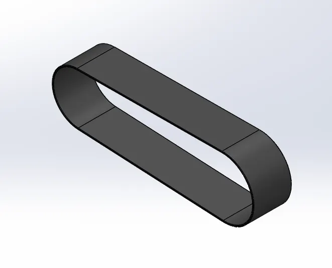
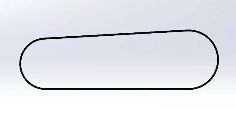
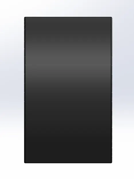
Isometric View Front View Right Side View
Now, for the second part, we design the kickstand of the chopper.
Kickstand
For this part, we start off with an ellipse drawn in the front plane. The dimensioning is done and the relations are established. Once it is fully defined, we create a spline in the midplane with origin as the reference. Now in order to create another ellipse so that the "stand" shape can be obtained, we need a plane perpendicular to the spline curve. So we use Reference geometry-> Plane and select the endpoint of the spline and the spline curve to create a new plane(also rename it). In the new plane, create another ellipse and establish the relations and the dimensions.
Now, we create a solid using Lofted Boss/Base by selecting the two profiles(ellipse) and the Centerline parameters(spline). We add a dome at either end of the ellipse. Followed by this, we use the extrude cut, split and the extend(for hinge) option to obtain the desired shape. Once this is done, we add the fillet and now the part is complete. Note that we also add the appearance to the part.
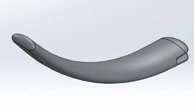
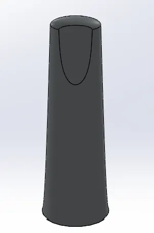
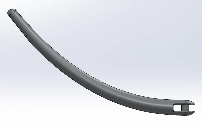
Isometric View Front View Side View
Front Fender
For the front fender, we first rename the three planes as vertical, centre and midplane respectively. Then we choose the vertical plane and create a curve. We complete the dimensioning and establish the relations. Then we use offset entities to create a concentric curve. Now we use Center plane to define an axis about which we are going to generate the fender. We use the Revolved base/Boss to generate the fender by selecting the construction line as the reference axis. Now, we use the midplane to generate a profile that stylises the fender. Once the profile is generated, we use the Split option to trim the unwanted region. This procedure is done for the other side of the fender as well. Finally, we add fillets with appropriate measurement thereby completing the part. Finally, change the appearance to that of a desired one.
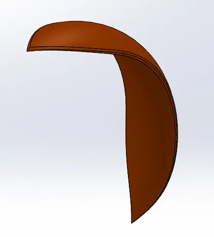
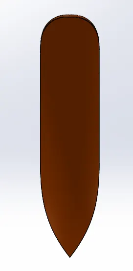
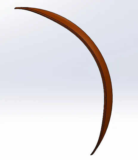
Isometric View Front View Side View
The rendered image is shown below.
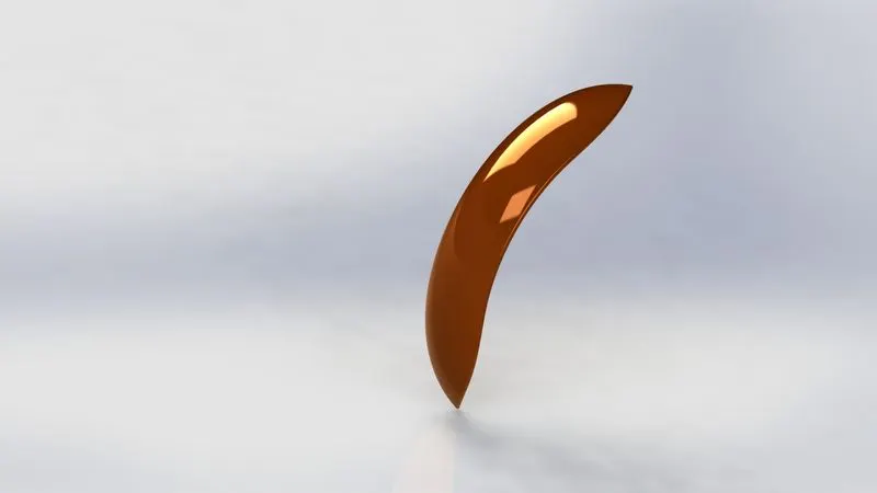
For part rendering, we use PhotoView 360 instead of SolidWorks Visualise as it consumes significantly less time and memory compared to the latter one.
Rear Fender
The final part of this challenge is Rear Fender. For the rear fender, the procedure is almost similar to what we did for the Front Fender. We create a curve in the vertical plane followed by offset entities and revolve base to generate the solid by specifying the angle of revolution. We create the profile on the midplane and use Split option to trim the unwanted region. This is done for the other side of the fender as well. Before the fillet is given, we use the Shell command to generate a shell by removing a portion of the inner side of the fender. Finally, we add the fillet and provide the appropriate appearance to the part.
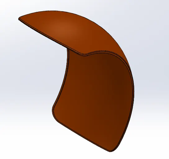
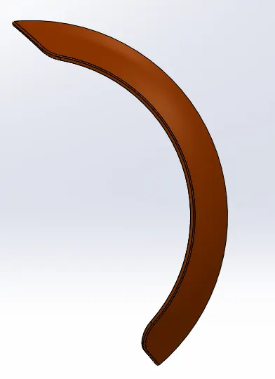
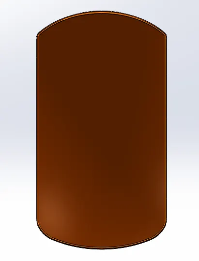
Isometric View Front View Side View
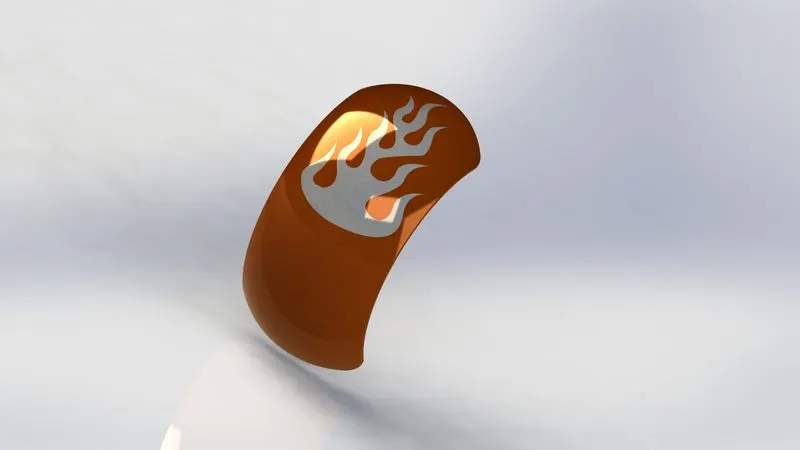
After this, we add decals to the Rear Fender which is essentially for visual appeal like a sticker/paint to make the fender look more realistic. Similar to the Front Fender, we perform the rendering of this part using PhotoView 360.
Oil tank
For the Oil tank part, we have to utilise the combine solids option to generate the solid. We first start by generating a profile for the shape of the oil tank. Proper dimensioning is done and the relations are established so that the shape becomes fully defined. After this, we generate another profile in a plane perpendicular to the Midplane(in Top plane). In a similar manner, we fully define the model by dimensioning and relations. Now, we extrude both the shapes in their respective planes by providing appropriate length using extrude boss option. Now, we have to combine both solids using combine solids option.
Make sure the option selected is closed which denotes the solid enclosed between these two solids. Now, we add fillets to all the edges using fillet option. For the final part of this component, we use the shell option to convert this solid into a shell tank for filling oil.
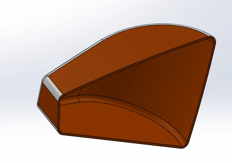
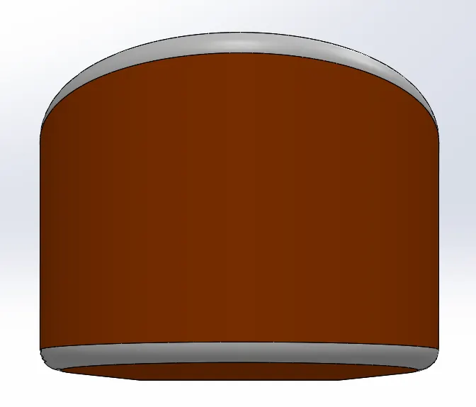
We have added the different views expected in this model. Note that a suitable appearance has also been added to the part.

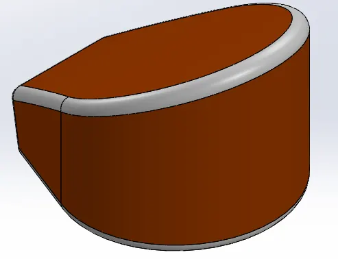
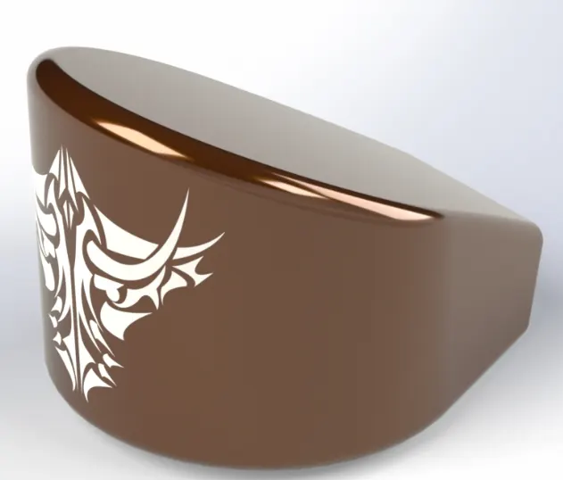
After this, we add a decal to the part and also render it using Photoview 360 for which the image is attached below.
Pedal
For this part, the most key aspect here is to obtain a proper sketch as the model is just plain extrusion and fillets. So to start off, we select the front plane and start sketching there. We make sure that the dimensioning is correct and proper relations are established thereby making it fully defined.
Once the sketch is complete, we start modelling with the first option being "extrude base" to extrude the whole sketch by a certain length. After this, we generate the leg rest profile by creating a sketch on the perpendicular plane. We use revolve option to obtain the solid part and the adjacent parts are obtained by extrusion. We also provide a dome at the end of the leg rest after this. We provide fillets in all the sharp edges. Then we add a chamfer to the parts where it is needed and after this, we create a thread kind of pattern on the cylindrical parts by creating a sketch on the surface of the base sketch and then use offset entities to create a "ring-like" pattern around the solid. We create a solid on that sketch using extrude base option followed by a linear pattern option to create a similar shape along with the feature till the edge. With this, we have completed the pedal part completely and the different views' pictures are attached down below along with the rendered image.
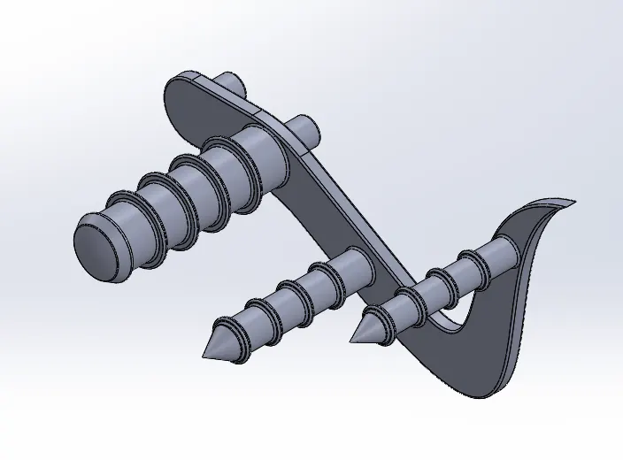
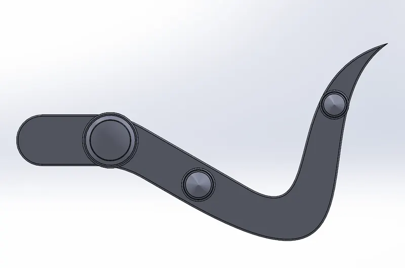
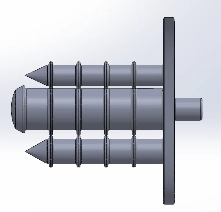
Isometric View Front View Side View
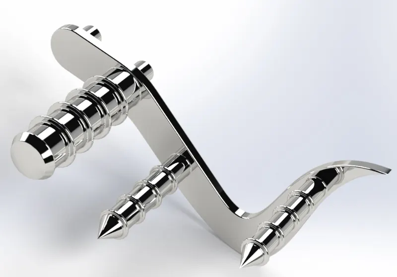
Chain
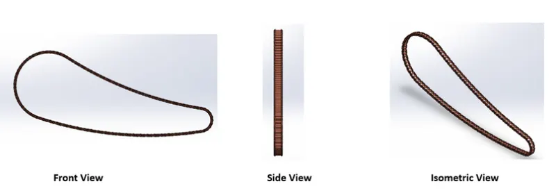
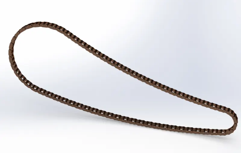
The chain is a bit tedious model to develop as it takes time although it is simpler to model portion by portion. For this part, we start by renaming the different planes to that which is suitable for us. We start by sketching the base profile for the chain which gives the overall shape to the part.
After this, we create profiles for the chain pins and the chainplates. Followed by this sketch, we use extrude base option to generate the solid for the above-mentioned components. As these components are repeatedly being used throughout the model, we create a block out of this using make block option. Also, we give a suitable fillet radius to the pins. Now, we generate a curve driven pattern for the first curve(the larger one). Make sure that the curve is selected for the direction, the bodies that are to be repeated(pins, inner and outer plate) are selected and the number of times they are to be repeated. In this manner, we generate the solids throughout the profile so that a closed-loop is formed.
The last lower plate however does not fit perfectly. So we use convert entities to form the profile of two pins on the base view and create a new slot in the sketch. Then this slot is extruded so that we obtain perfectly fitting chain pins and plates. After this, we use the mirror option to reflect the plates(only) to the other side of the midplane so that the model is complete. We open the Solid Bodies for this model and see that there are many components which makes it tedious to search for a single specific part. So we group the pins and plates separately by adding them into a folder. Finally, we give a suitable appearance to the finished part.
Front Wheel
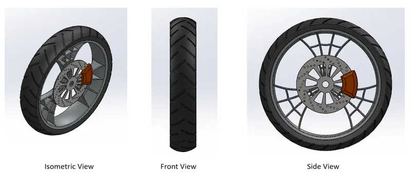
For this challenge, we are going to model the front wheel of the chopper. We start by creating a sketch on the front plane for the rim and the centre bore. After this, we use revolve extrude to generate a solid profile of the sketch. Once this is complete we switch to the top plane to sketch for the spokes where the rough sketch is extruded to get a generic solid profile and then use extrude cut to generate a nice web-shaped pattern/design to the spokes.
After creating one set of spokes, we give a fillet to the sharp edges and then use a circular pattern option to create two more equally spaced spokes in the rim. Followed by this, we use combine solids option to combine the centre bore and the spokes. With this, we have completed the rim and then proceed to the disc plates. For the disc, we create a circular profile on the top plane and then extrude it to obtain the rotor/disc.
After creating the rotor/disc, we proceed to create the brake calliper for which we create the sketch on the top plane and then extrude it to create the brake calliper. Then we use the chamfer option(on either side of the calliper) to create the required shape. The final part of this modelling is to create a tire and provide threads to it.
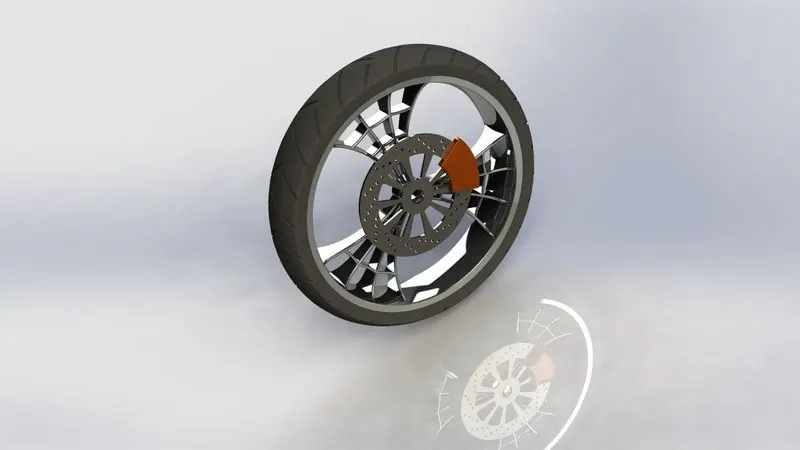
For the tire, we create the profile first by sketching on the outer edge of the rim. Then use revolve it to obtain the tire. Followed by this, we proceed to sketch the threads on the tire. Now, we extrude cut this profile on the surface of the tire by giving appropriate thickness. We also provide fillet to the rectangular threads. Then, we use the circular pattern option to generate these threads throughout the tire. With this, we have successfully modelled the front tire in SolidWorks. As a final touchup, we add the appropriate appearance to each part. Different views for the part along with the rendered image is shown down below.
Rear Wheel
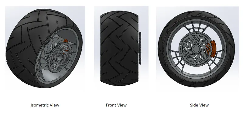
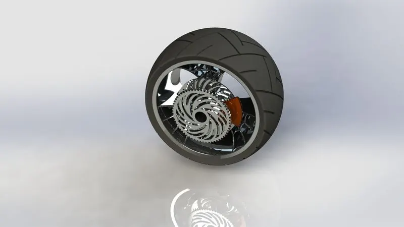
For this model, we start off by creating a sketch for the rim of the wheel. We Revolve the profile about the base to obtain the solid portion of the rim in its basic form. We provide a fillet to the edge of the rim. Then we provide additional features to the rim to make it look more appealing. We use the extrude and circular pattern to obtain the spokes of the rim align with a fully flushed design. Note that a suitable appearance(chromium plating) is also provided to the rim. Now, we model the rotor disc of the wheel by sketching the profile for it. For the disc, we create a circular profile on the top plane and then extrude it to obtain the rotor/disc. Now, we create smaller holes on the rotor to make it look visually appealing. After this, we model the caliper by sketching the proper profile and giving a chamfer to it. Followed by this, we model the sprocket by sketching a circular profile, extruding it and extrude cut the unwanted region for the teeth, holes etc.
For the tire, we create the profile first by sketching on the outer edge of the rim. Then use revolve it to obtain the tire. Followed by this, we proceed to sketch the threads on the tire. We extrude cut the threads and circular pattern it throughout the tire.
Front Fork
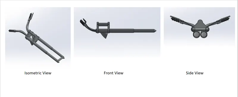
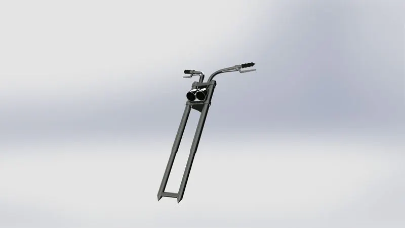
Followed by the Rear wheel, we proceed to model the Front Fork of the chopper. For this part, we model only one side of the fork and mirror it to obtain the other half as the part is perfectly symmetric. We start off by sketching the front fork tube and using the revolve option to obtain the solid tube.
Followed by this, we generate the triple clamp by sketching it on the plane created on the cross-section of the fork tube. Then we use the linear pattern option to obtain one more clamp. Followed by this, we create the headlamps by sketching a profile on the midplane followed by the revolve option to generate the solid for it. Then we provide a dome at the end to add appeal to the dome to make it look more real. After this, we create a sketch on the triple clamp surface to obtain the brake wires. For this, we create two splines on two planes and then use project curves option to obtain the curve which follows the two curves creates earlier. Once the brake wire is generated, we use the end of the curve as a reference and create a reference plane to create the sketch for the handlebar profile. We model the handlebar, the handle and provide unique shape/design to it. We also sketch the brake handles on the reference plane at the end of the handlebar. We extrude the handle and also make sure that the brake wire comes closer to it and does not go through it.
After making sure we have completed half the model, we mirror with the base of the triple clamp as the reference axis and complete the model. Finally, we provide the appearance to the rest of the components and also segregate them into its assigned component. We finally add a reference plane at the bottom of the fork tube just for visualization purposes.
Chassis
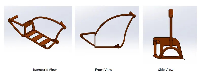
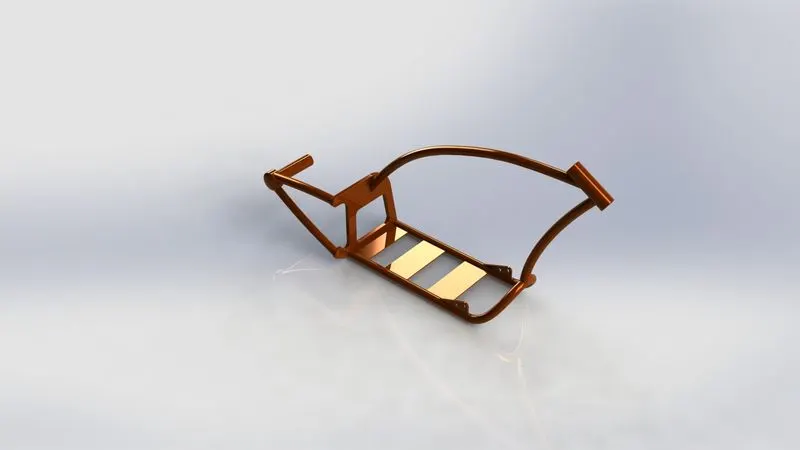
The objective of this challenge is to utilize various tools in SolidWorks to model a few more parts of the chopper such as Chassis and Engine. We start off with the Chassis part. For the Chassis to be modelled, we need the Sketch picture and hence we start with a new sketch on the front plane and goto Tools->Sketch Tools->Sketch Picture and import our downloaded sketch picture. We will use this sketch picture as the reference and generate our chassis model. We first start a sketch on the Bottom plane for the outer frame of the chopper. To obtain this base outer frame we will need to use project curves option after creating two curves on two planes. This curve, however, is not the desired shape as we can observe in the sketch picture. So, we create another curve after projecting curve after creating the required sketches. Now, we use the two curves to generate the actual curve for the frame. We use the swept boss option to generate the solid cylindrical frame from the curve. We also mirror the profile to obtain the solid on the other side as well.
Followed by this, we create a sketch for the vertical plate on the Right plane. We extrude this and also cut extrude the unwanted regions inside the component. We also provide appropriate chamfers and fillets followed by which we create a sketch on the backplate for the rear tubes connecting the rear axle. This is also done by creating the required sketches and using the swept command to obtain the solid. After this, we create the axle by sketching first on the bottom plane followed by extruding it to obtain the axle itself. We also provide a dome at the flat end of the axle. Now, we create a reference plane so that the front supporting tubes(vertical) tubes can be sketched on it as well as the guiding tube for the handlebar. We create the solid for the tube by selecting the tube and the guiding curve and use the swept base option.
We now create a new reference plane for sketching the tube that attaches the horizontal frame with the vertical tube and the handlebar. After this we use Split option to remove the unwanted bodies(make sure consume bodies is turned on). Once the outer frame is done, the final part of the chassis such as the base plate on which the engine rests is created using extrude option after creating the sketch for it. After this, we create the sketch for the kickstand holder and the pedal holder. We extrude the sketch and also give suitable fillets for it.
With this, we have completed the chassis of the chopper model. One final step before closing this model is to create a new reference plane named bottom plate for the fuel tank reference. We have attached various views of the model along with the feature tree.
Engine
The engine is a complex part and we have explained every step followed while modelling this geometry down below. For this part, we start off by importing the sketch picture of the chopper model similar to how we did for the Chassis. Then we draw the sketch for the casing and extrude it to obtain the solid. After this, we model the rest of the engine casing after creating a sketch on the front plane and extruding it. We provide suitable fillets to it and then we proceed to the transmission belt pulley. We create the circular surface first(extruding) and then extrude cut to obtain features on and over the surface of it.
Now, we create a single rib on the curved surface and then use a circular pattern to obtain this throughout the surface. After this, we create a sketch for the cylinder casing (twin). For this, we create a profile for one casing and then linear pattern at an angle to obtain the other one. We further create features such as thermal fins on the surface using the extrude cut and linear pattern option. After this, we create a valve port which brings fuel to the engine on the surface of the casing. Next, we create the stand for the engine so that it can rest on the base frame of the chassis. We provide fillets to it as well. For the final part of this challenge, we create the tubes carrying fuel. For this, we create curves on multiple planes, project curves and then also use the composite curve to obtain one final curve that represents the features we are looking for. Then we swept the profile to obtain the solid for it. We have attached various views of the model along with the feature tree.
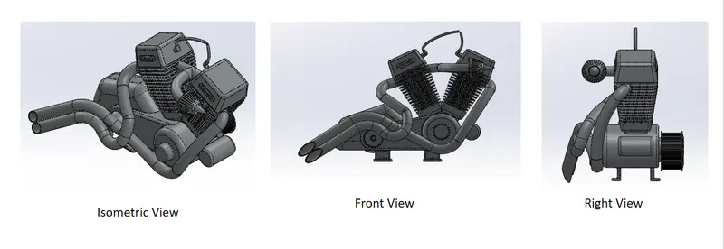
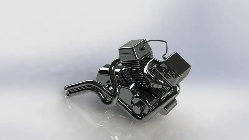
Fuel Tank
The Gas tank modelling is in a way unique compared to how we have modelled the other parts till now; the difference being gas tank involves surface modelling whereas the other parts used solid modelling. We first create a sketch for the surface to be swept and use the surface sweep option to generate the surface along the profile required. After this, we use some more commands such as surface trim and surface loft to generate a hollow half-gas tank. Note that we create only one half of the gas tank and will mirror it to obtain the other half. Once the fully enclosed surface is obtained, we use boundary surface followed by a knit surface to get surfaces knit together and act as one. We finally use surface extrude for the seats and also cut-sweep for removing the portion under the fuel tank where the chassis passes through.
With this, we have completed the fuel tank. As a final touchup, we provide suitable appearances to the seat and the tank itself followed by decals for the visual appeal.
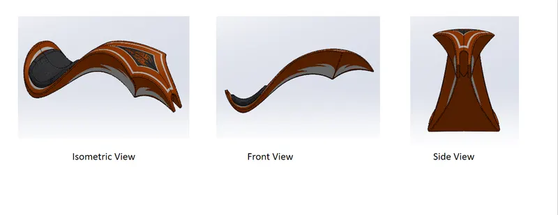
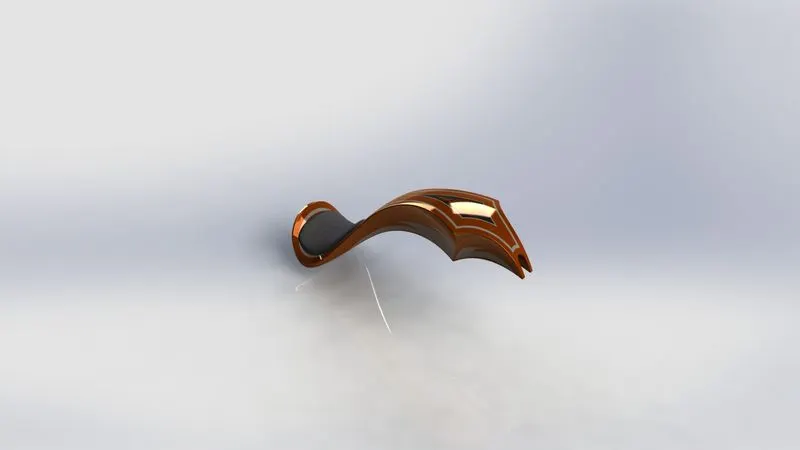
We have completed and also rendered every individual part and now proceed to the assembly of the chopper model.
Assembly of the chopper model
For assembly, we first start opening an assembly file instead of a part file. Then the chassis is imported. Then the Engine is imported and suitable constraints are provided such that the engine is attached to the chassis frame. Note that the engine moves if and only if the chassis moves. The chassis' vertical plane is then aligned(coincident) with the reference frame of the assembly module. Followed by this, we import the pedal and properly constraint that on one side of the chopper. Then we mirror the pedal with the midplane as the reference which creates a pedal on the other side too.
Next, the kickstand is imported and properly constrained with the portion attached to the chassis for holding it. The transmission belt is imported and aligned with the pulley such that it has tangency and concentricity. Next, the oil tank is placed on the engine and the appropriate constraints are given. The front and rear wheel are attached and the axles are made concentric. Next, the front and the rear fender are attached to the assembly model by providing concentricity constraint with the front and rear wheels respectively.
For the chain, the mating is to be done with the sprocket giving concentric relation but the chain doesn't sit in properly with the sprocket. We use the width option to rectify this and also provide a suitable angle to mate them properly. For the final part, we add the front fork which has concentric relation with the guide route present on the chassis. Now, we provide limit angle option to make the handlebar rotate up to 30 degrees in either direction. We also keep it at the maximum direction for an aesthetic look.
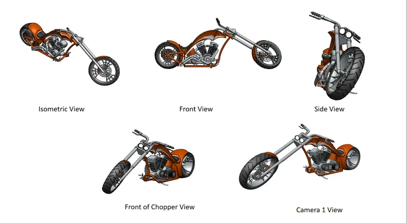
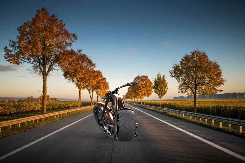
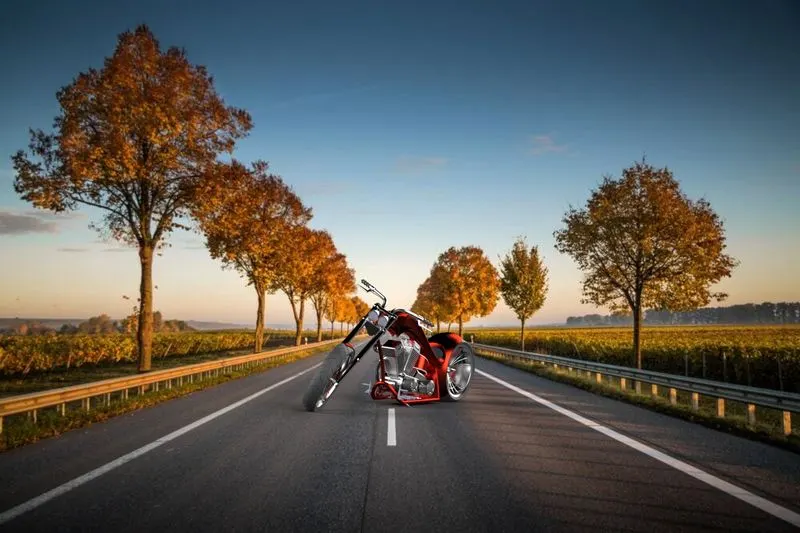
These are the views that we have considered for the Project. The Camera 1 view is the one that will be rendered for the final output results. For the final renders, we add different scenes(scenery/background) to make it look Photorealistic. The rendered images are attached down below.
Photo-Realistically Rendered Images of American Chopper
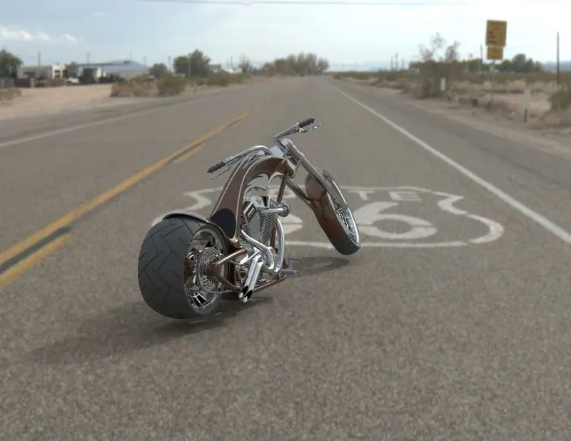
This is the very first image we rendered using SolidWorks Visualize. But after this, we made some changes to make the Chopper to look even more assimilated with the background scene and obtained the following image.
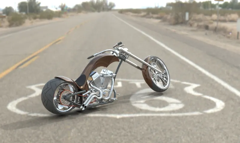
We also added another scenery and the image for it is attached below.
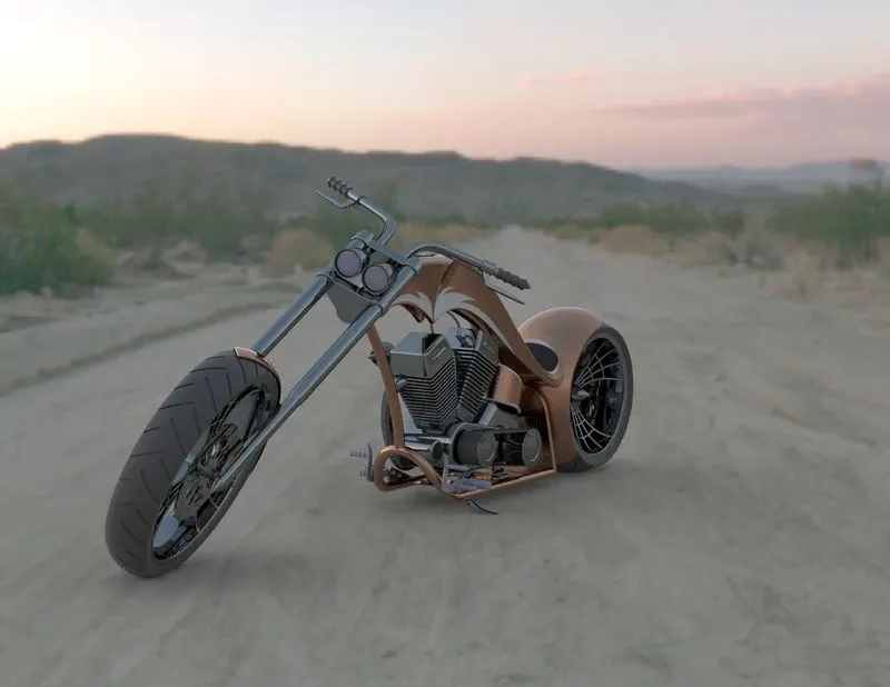
Conclusion
To conclude, this project presented us with a challenge on how to model, assemble and render the given model(American Chopper) using SolidWorks and SW Visualize respectively. The explanation on how each part is modelled and the whole assembly is done in a detailed manner along with the appropriate images validating that. We have also learnt how to render the assembled Chopper model using SolidWorks Visualize after making the necessary changes to the model to make it look more appealing.