Advanced Sheet Metal Design Using NX Cad Challenge_7_ Metal bracket-II
CREATE A design metal bracket-2 BY USING NX12
Objectives: To learn the procedure to design metal bracket-2 by using Siemens NX sheet metal
Introduction: Sheet metal is simply metal formed into thin and flat pieces. It is one of the fundamental forms used in metalworking and can be cut and bent into a variety of different shapes. Countless everyday objects are constructed of material. Thicknesses can vary significantly, although extremely thin thicknesses are considered foil or leaf, and pieces thicker than 6 mm (0.25 in) are considered plate.
Design methodology: in the metal bracket-2 design process we used different tools, features like counter flange,normal-cut, break corner, hole, etc. The design methodology used for this project step by step procedure is shown in below flow chart
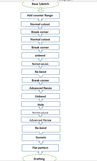
Description: in this project l used NX tools for making BRACKET design. All steps are clearly described in below following steps
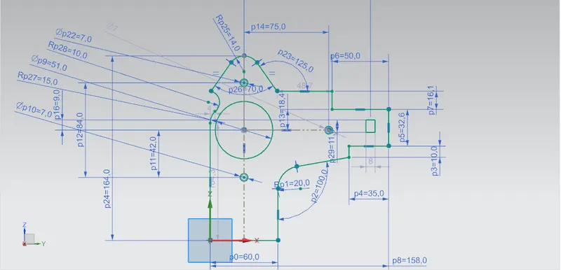
Sketch: Sketch is the fundamental base element of design for any sheet metal component. Most of the features require a sketch. For casing design Create a sketch in the “YZ” plane and draw a sketch based on origin with given dimensions
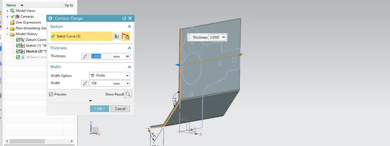
Counter flange: Create a base feature by extruding a sketch along a vector or add material by sweeping a sketch along an edge or chain of the edge. for this project sketch in the "XZ" plane and add the select curve on the counter flange dialog box. (Home tab: bend gallery– the counter flange)
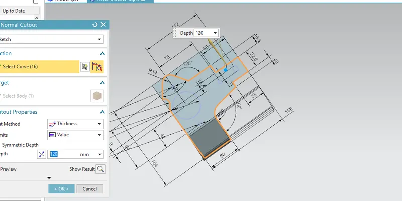
Normal cut-out: cuts material by projecting a sketch onto the model and then cutting perpendicular to the faces intersected by the projection. (Home tab: features gallery-normal cutout)
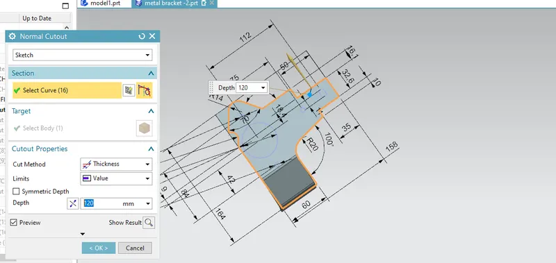
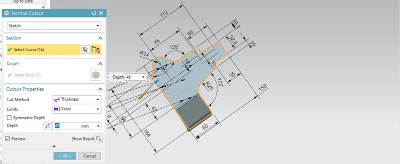
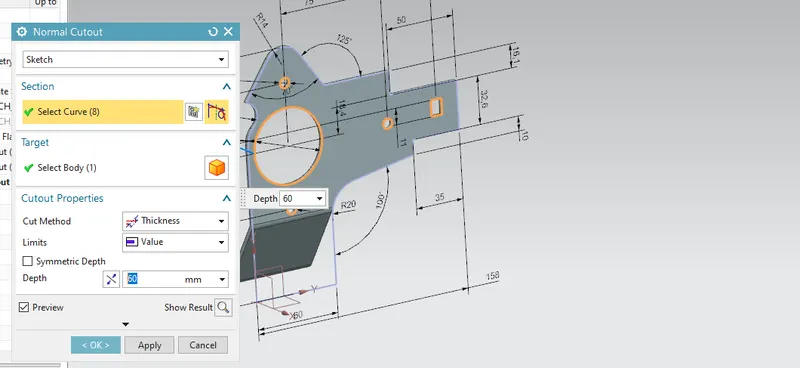
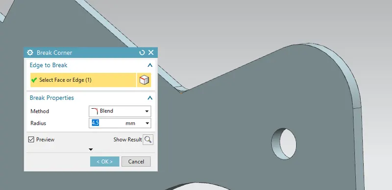
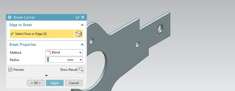
Break corner: rounds o chamfer a sharp corner of a tab flange. For metal, bracket-2 design Apply the broken corner to the edge of the sheet metal with a radius of 4.5&4 on inside 4mm corners (Home tab: corner gallery-break corner)
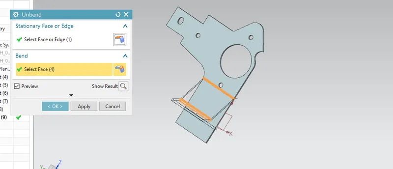
Unbend: flatten a bend and the material adjacent to the bend. in the unbending dialog box select stationary face (Home tab: form -unbend)
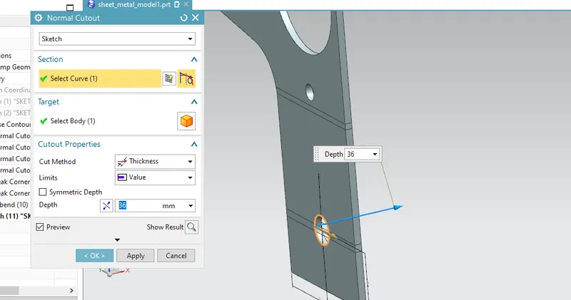
Normal cut: Draw a circle on the "YZ" plane at the lower bend with 12.5 diameters and add normal cutout
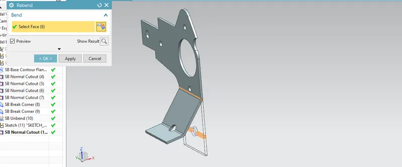
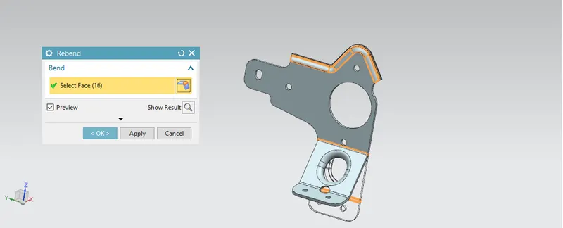
Re-bend: restore an unbend feature to its previous bend state along with any features added after the unbend feature
Break corner: Again add break corner on the lower edge of the part modeling with 12mm
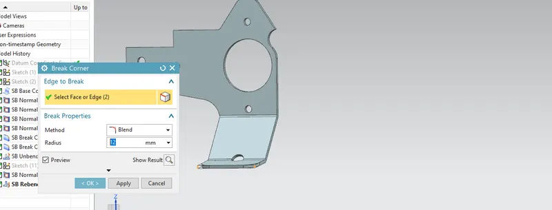
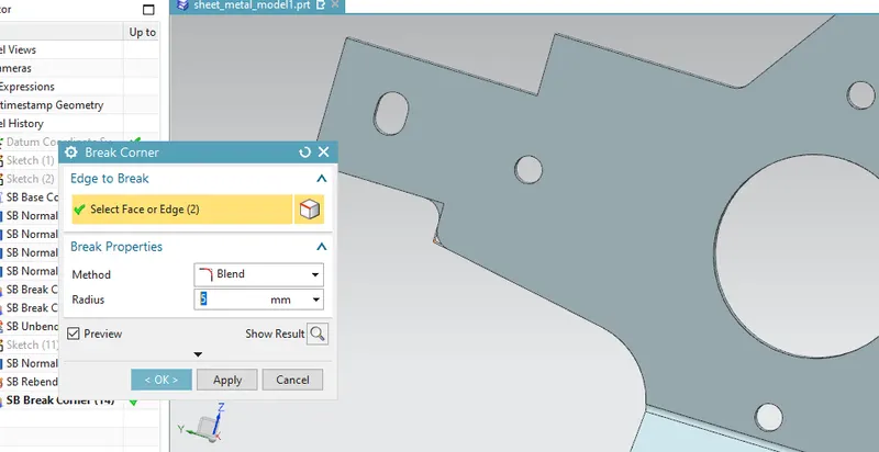
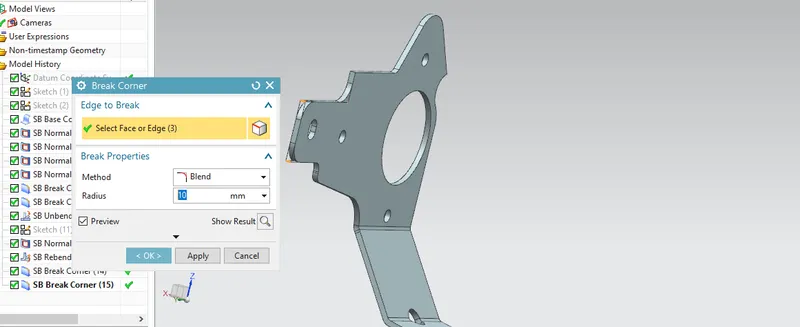
Similarly, add a breaker corner with a radius of 5mm and 10mm at the edge of the part model as shown in figure
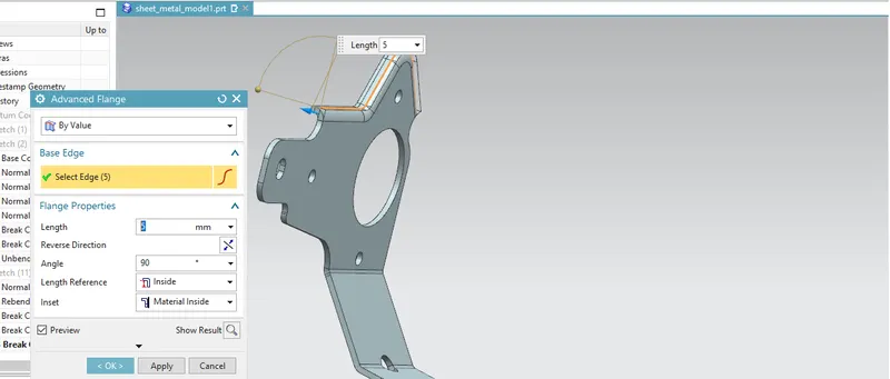
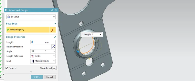
Advanced flange: Use this command to add a flange along the edge using a ben angle or a reference face. the edge and reference face can be curved. for this project select the upper edge of the model as shown in figure
Un-bend: Again add a unbend after added advanced flange select the stationary face
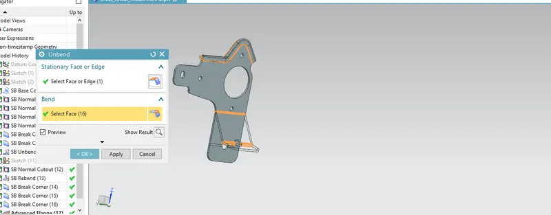
Hole: adding a hole to one or more solid bodies in part or assembly with options for countered bored, countersunk, and threaded. for this project design sketch two points figuring lower part of the model as shown in figure (Home tab: features gallery-more- hole)
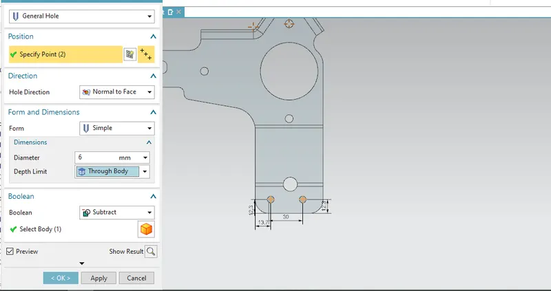
Normal cut: draw a sketch on the YZ plane and add normal cut
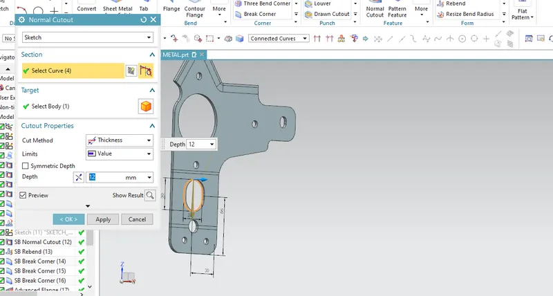
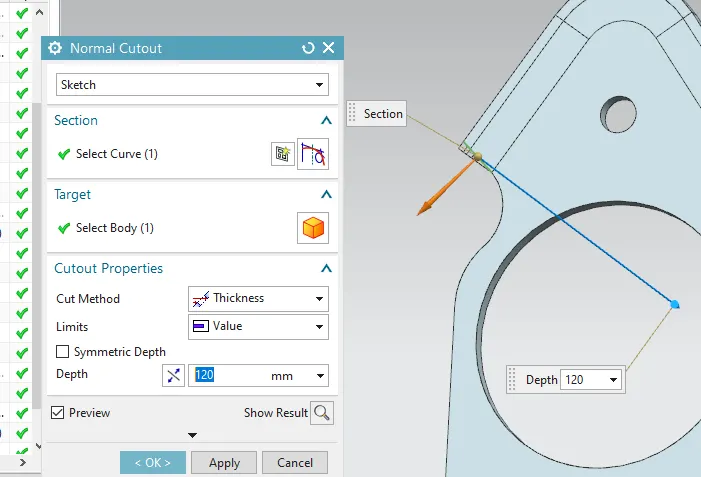
Add advanced flange: Add an advanced flange on edge of the just created the normal cutout
Rebend: After adding advanced flange rebend the entire part model as shown in figure
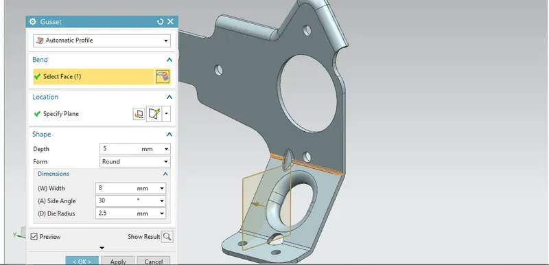
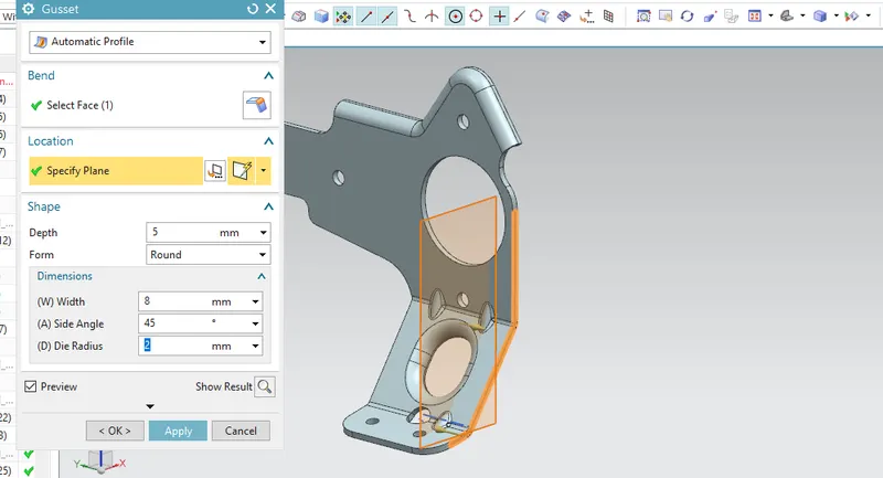
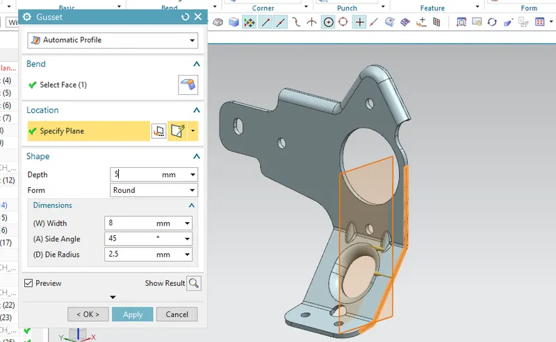
gussets: Gusset is a power tool in NX to create a stiffening gusset on a part. (Home tab: punch Gallary: gusset). for this project create a gusset with -15mm distance as shown in figure
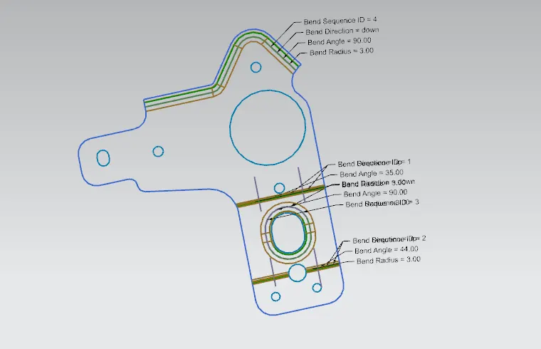
Flat pattern: creates a flat pattern feature from the formed sheet metal part. (Home tab-flat pattern gallery)
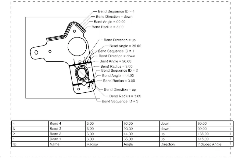
Drafting: after the design is complete, the execution of the manufacturing component requires a technical drawing of the components with the provided and with accuracy. The details like annotations, bend table can be added as per requirement. For metal bracket design project drafting is created in A4 size and the bend table is added
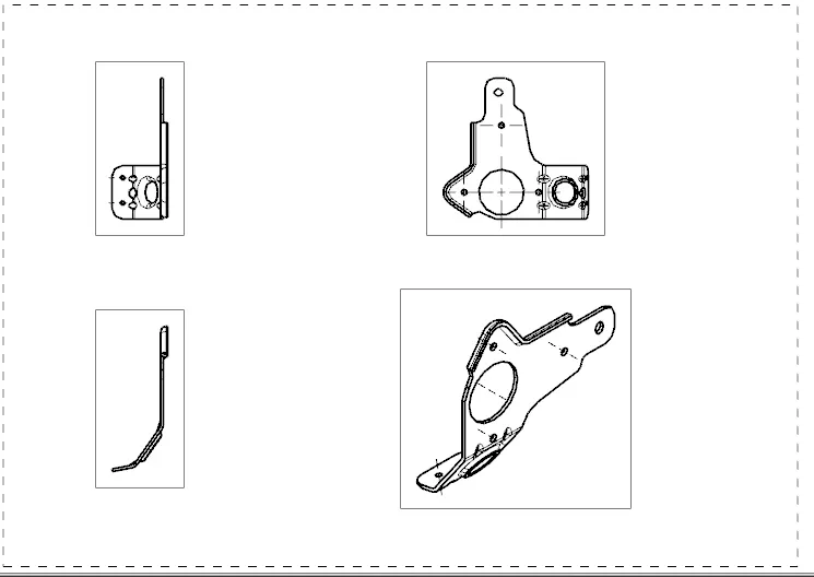
DIFFERENT VIEW OF THE BRACKET
Isometric views of the metal bracket-2:
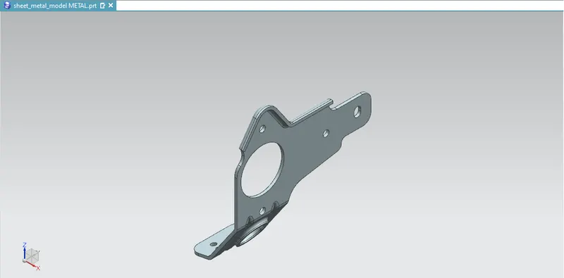
Front view of the bracket -2
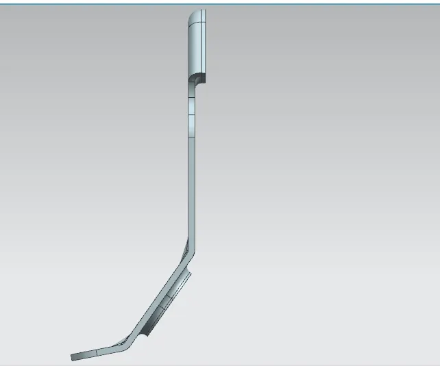
Back view of the metal bracket
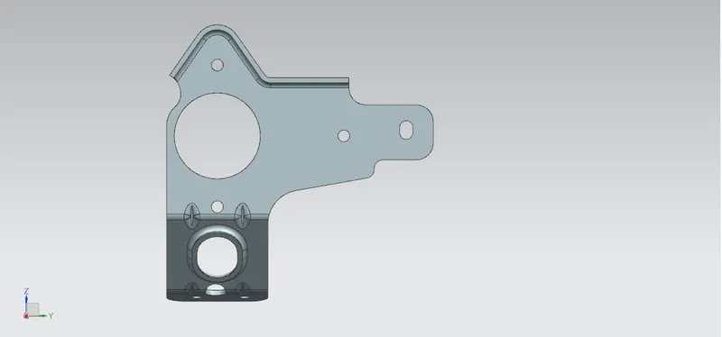
right view of the metal bracket-2
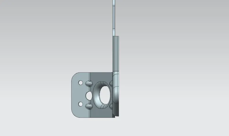
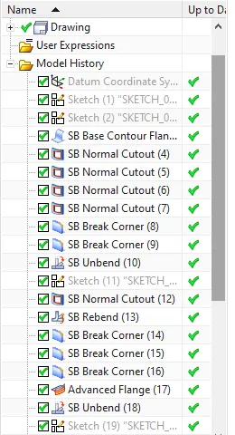
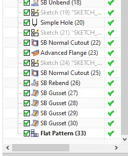
Tree images of the metal bracket-2
Conclusion: I have done this project, successfully by using NX tools in Siemens NX