PFI Engine- Surface preparation, Boundary Flagging and Dry Run of No-Hydro CASE Setup
OBJECTIVE
- Boundary Flagging & Regions - Extract Boundaries from Geometry and naming them and assign their appropriate regions.
- Surface preparation – To remove all surface errors and perform surface cleanup.
- No-Hydro Case setup - Run the Case for Checking Mesh motions in the Geometry for the case without solving governing Fluid Flow equations(No Hydro)
Introduction
A port-fuel injection engine operating with a lean burn has the potential for higher thermal efficiency, and lower nitrogen oxide emissions than that of stoichiometric operation. However, a lean or highly diluted mixture leads to poor combustion stability impacting detrimentally upon engine performance. In this project a cylinder of a PFI engine is set up for combustion simulation using Converge software. The part 1 of this project comprises of Surface preparation, Boundary flagging & setting up the case for no-hydro simulation , which is basically nothing but that Converge will not solve any governing fluid flow equations for solving the simulation. This is done to check the mesh movements in the geometry before we proceed for full hydrodynamic simulation.
Geometry
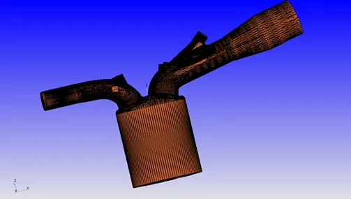
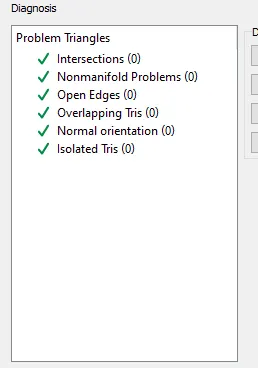
This is the base geometry imported as an .stl file which had many surface errors and where all the boundary needs to be flagged appropriately with proper conditions. The case setup was initiated by running a diagnosis to identify the types of errors the geometry had, later they were all fixed one by one while flagging boundary simultaneously .
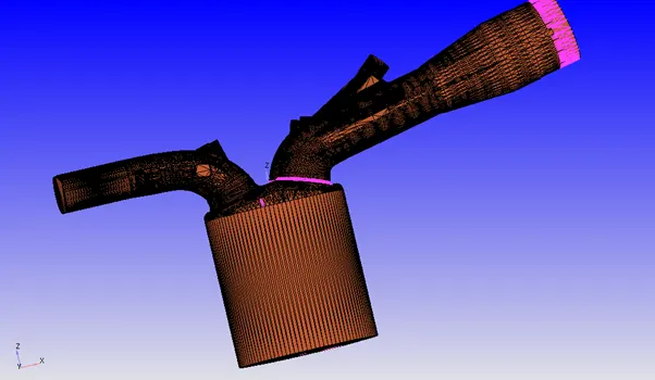
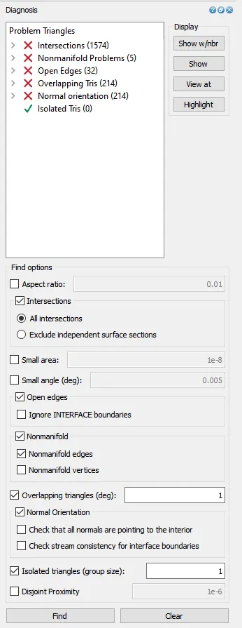
Diagnosis :As we can see there are different errors in the geometry which includes intersections, open edges, overlapping triangles, normal orientation. The pink highlight in the picture gives the location of the surface that needs to be fixed
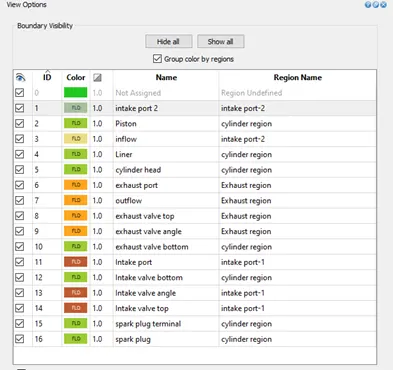
Boundary Flagging : There are in total 16 boundaries flagged in this geometry. It can be initiated from any part of the geometry as long as long one can select that portion right and view it or hide and again redisplay when required to capture the portion of the boundary, fence around the edges which are created.
Liner and Piston
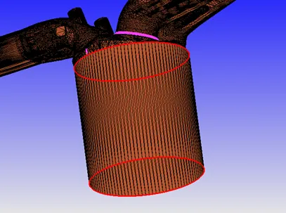
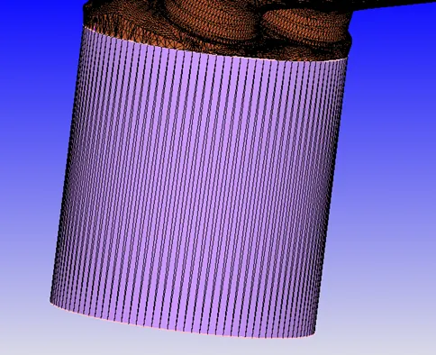
Piston flagged – the picture shows open edge error which was later fixed.
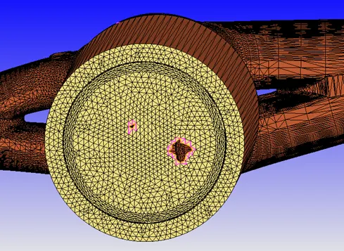
Cylinder Head :To flag cylinder a fence is created on top of the connected surface (wall) of cylinder head & intake / exhaust ports. The intersection error was present which were fixed and the boundary for the cylinder has been flagged.
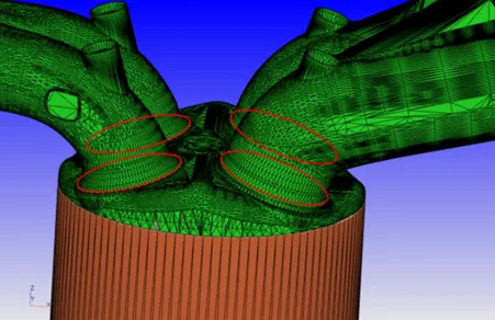
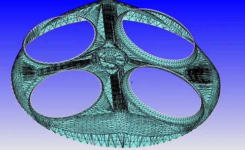
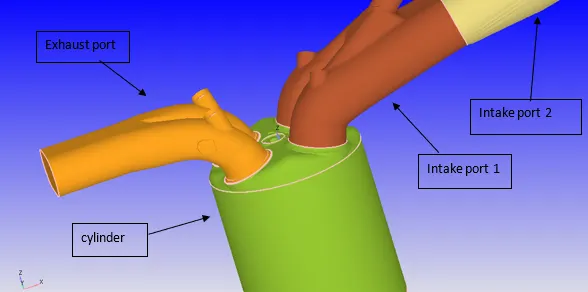
Intake Port, Inflow ,Exhaust Port and Outflow: The intake port is split into two boundaries(port 1 and port 2) by using fence method created by two vertices to flag boundaries leading to two regions and separate boundary conditions were assigned. The fuel is injected from port 1 . The intake is split into two regions.
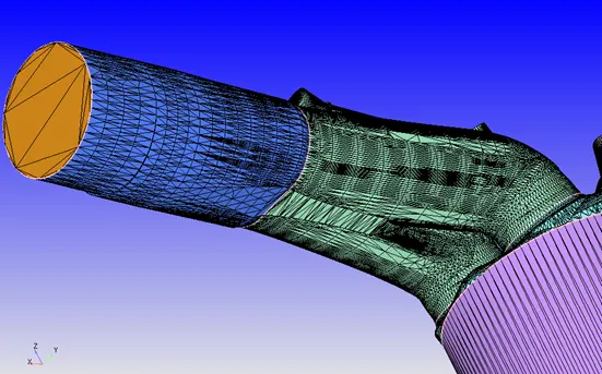
Similarly the outflow is flagged
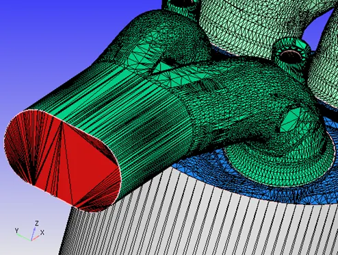
Valves
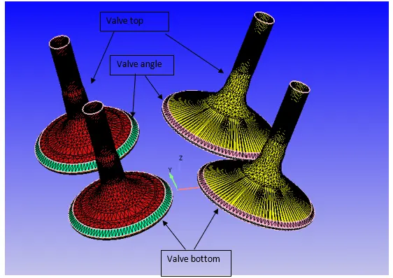
The valve geometry is flagged in 3 categories as shown in figure. This is done by creating events between the cylinder and port. Converge by default creates disconnecting triangles to stop the flow & then later it automatically gets rectified. The bottom is later merged in regions of the cylinder as it forms the internal flow part during translatory movement of the valves and the boundary conditions are given according to the translatory motion(opening and closing of valve).
Spark plug & Spark Plug terminal:
The spark plug and its terminal separately is also flagged using fence. Separate Boundary conditions were assigned for spark plug and terminal as required as the spark are at a higher temperature than rest of neighbouring components like the valves and the cylinder head as this is where the ignition occurs.
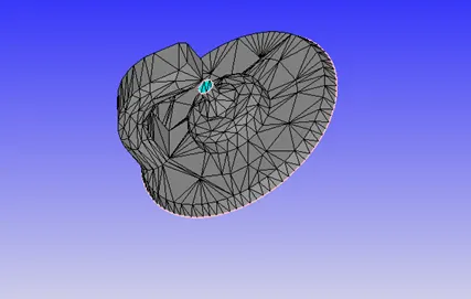
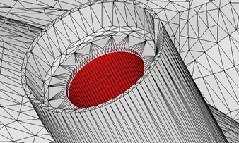
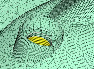
Flagging of small cylinder inside the Intake and Exhaust port boundaries on both sides.
Flagging of the small cylinders inside as shown is done for cylindrical shape on top of the valve where its connected to prevent it’s distortion as the valve moves up and down. Flagging this small helps the cylinder retains it’s shape.
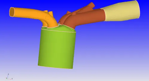
All Boundaries flagged.
Surface preparation
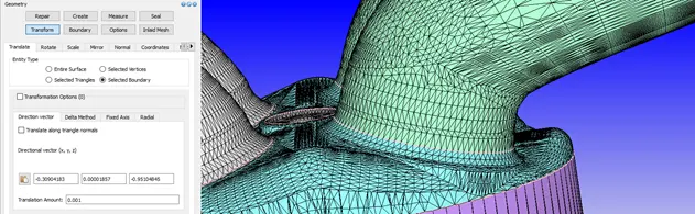
1. Intersections : The intersection errors at the inlet valve side where valve angle stands/comes out of the cylinder head wall surface. The error is resolved as shown. To solve this error the valve is pushed down which is done by obtaining the valve arc normal at the top valve circle and using translate option for all the three sections of valve: valve top, angle and bottom. it is translated down in an increments of 0.001 m until the surface appears clean of the intersection and error free verified by diagnosis.
2. Open Edges : Sometimes such open edges are formed in the geometry as shown below, there are two types : type 1 has a hole like structure on the surface while type 2 is more like open at small points and intersected triangles are formed due to open edges. These errors are cleaned. Simply by just patching the open edges from repair - patch & converge automatically creates a triangulated surface over it. And for the type 2 the intersected triangles are simply deleted or stiched .
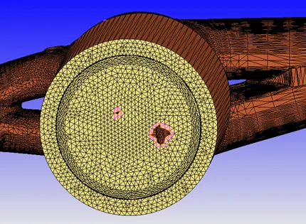
Type 1
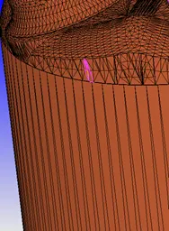
Type 2
Error free by patching open edges(type 1)
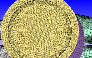
- Normal orientation / Overlapping triangles are triangles that overlap each other, in this case they weremerged with Normal orientation problem and the advantage of that is that by simply fixing its normal( by transform all triangles) also fixes the overlapping triangles. As from the image below the normals are pointing out we simply need to flip them inside as the flow domain is inside This is done from transform-select any triangle in that area and then accept.
Cleaned as shown
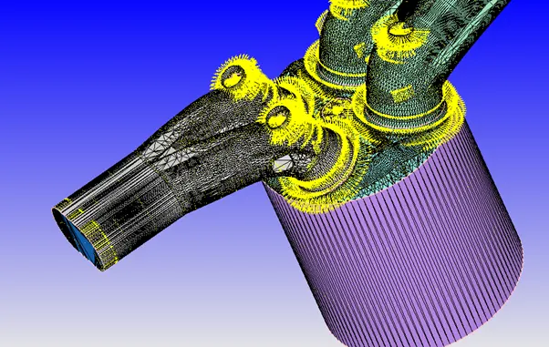
Regions and initialization : Each regions are assigned their own boundary conditions and are coupled with events as in this case (a cyclic & permanent events) Also other boundary like spray modeling require these to be created in the next part of the project i.e hydro simulation.
No Hydro Case Setup:
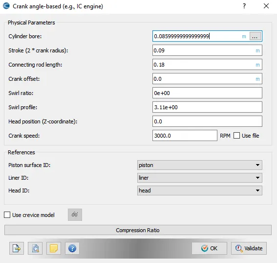
Before setting up the spray and combustion processes, the engine first needs to be simulated in no-hydro mode to verify that the cleanup, boundary flagging and the initial setup was done properly which is the objective of the present project. IC Engines (crank-angle based) is selected under applications.. Next, under gas simulation therm.dat file and under reaction mechanism mech.dat file were imported. The simulation time parameters were chosen as -480° as the starting crank angle and 240° as the end crank angle . The present case was setup in such a way that the exhaust valves would be open first thus (-)480° was selected. For one cycle of the piston motion which comes out to be 720° of total crank angle. With the intake_lift.in file the regions between cylinder, intake and exhaust ports which were connected by valve events) will be closed and opened. When closed, it will create disconnect triangles between cylinder and intake/exhaust ports which stops the flow and then reopen again as per the lift profile provided.
- Bore =0.086 m
- Stroke = 0.09 m
- Connecting rod length = 0.18 m
- RPM = 3000
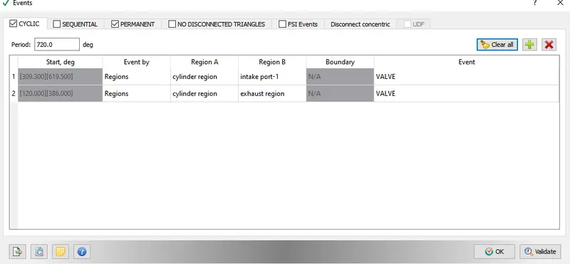
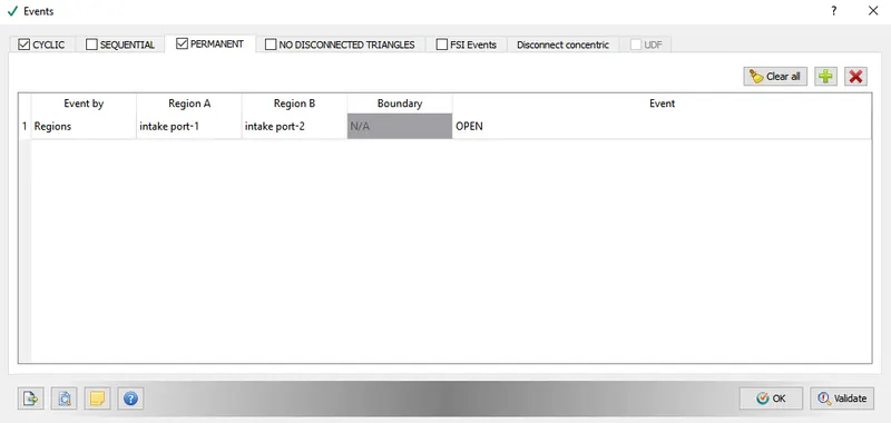
Regions and Boundary Conditions: With all the boundaries flagged appropriately, the IC Engine was divided into four different regions: Combustion Chamber/cylinder, Intake Port-1, Intake Port-2 and Exhaust Region as mentioned previously.
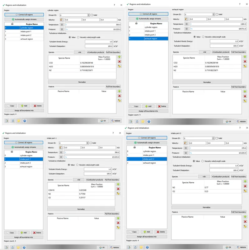
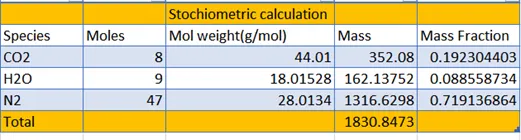
Reaction takes place between Iso-octane with air inside the combustion chamber to undergo a stoichiometric reaction to give carbon dioxide, nitrogen and water as the final products. Converge takes in species concentration of these molecules as inputs. For this purpose the mass fraction of the products were calculated.
C8 H18 + 12.5(O +3.76*N ) → 8*CO2 + 9*H2O + (3.76*12.5)N2
Boundary conditions
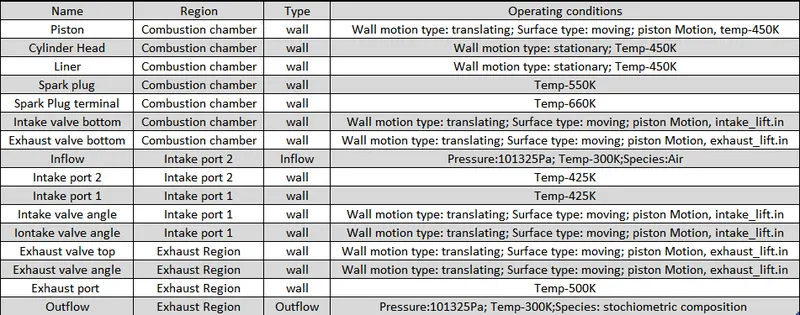
Meshing - Grid Control : Default standard grid size is taken to be : Base Grid size : 0.004 m
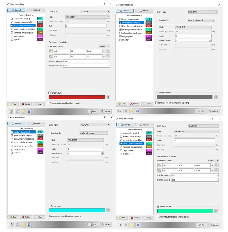
Fixed embedding :
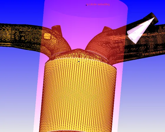
This embedding is provided between the area created by angles flagged valve and the iner as the space there is very small and coarse base grid size will/may give inaccurate results and as we know the distance from trial and merely by assumption and when we lowered the valve during preparing surface flagging B.Cs, and from converge laws of addition of half cell in the gap region hence fixed embedding is applied to refine that area to capture the details Similarly the cylinder is also very coarse and cylindrical shape type embedding is provided onto it(big and small). The fixed embedding is applied for both the angles of exhaust and intake valves.
Note: the snapshots are taken after the addition of fixed embedding in the spark ingnition region.
Big and Small cylinder embedding
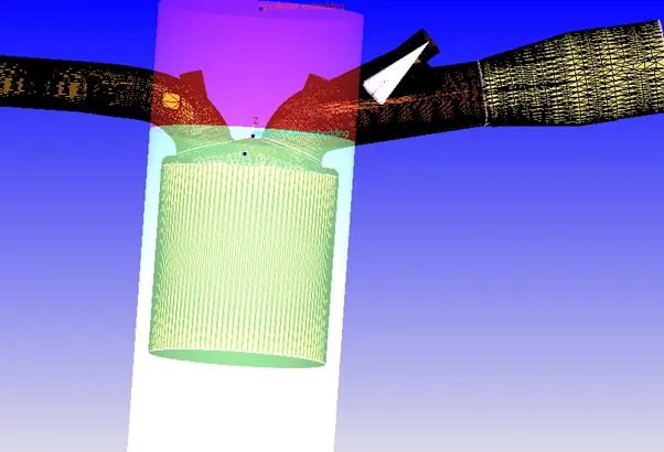
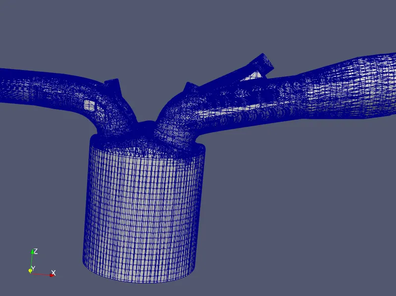
Post Processed Animation in Paraview: The translatory mesh movement along with the expansion and compression of valves are observed as well as the solid color animations are created.
---------------------------END------------------------------------------------