Performed shell mesh for a PLASTIC BOTTLE CAP - using ANSA
AIM:
To check for the geometrical errors and mesh with the given element Quality criteria. After meshing the component the thickness has to be assigned for the given component.
NOTE:
In this challenge, there will be some off elements found in the chamfer region which cant be removed. It is acceptable as it is been found due to the presence of triple cons on the chamfered surface. Due to those triple cons there will be some quality criteria failure which can be accpetable and those quality fails can be neglected.
GIVEN DATA:
The given data are the inputs to work. Here the given data are,
- CAD model.
- Quality criteria.
- CAD MODEL: Here the given cad model is plastic component - Bottle cap
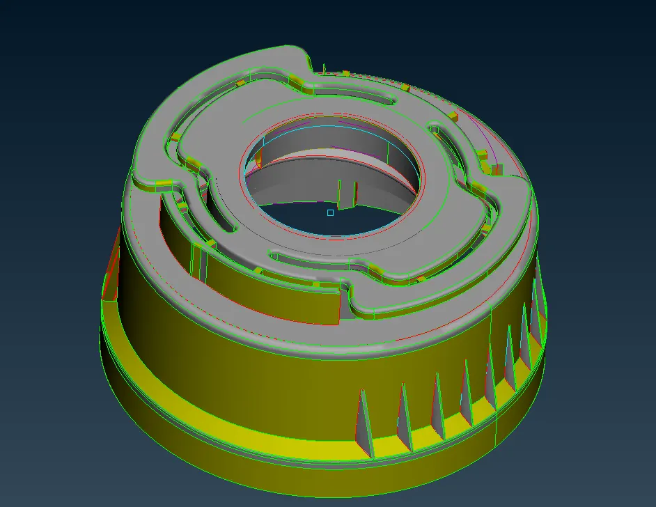
Figure 1. CAD model - Given data.
- QUALITY CRITERIA : Every product which is been produced will go through the set of quality check. If the quality check fails other steps like boundry condition & apllying loads will not be feasible, So for this reason the element quality check is performed. To identify the quality failure the quality criteria will be entered as an input data. The given quality criteria are shown in the below table. The elements should be maintained within the below given value. If the given quality value is not maintained there will be a failing in qulaity.
| S.NO | QUALITY CRITERIA | VALUE |
| 1. | Target/Avg length | 1 |
| 2. | Min. length | 0.5 |
| 3. | Max. length | 3 |
| 4. | Aspect ratio | 3 |
| 5. | Warpage | 15 |
| 6. | Skewness | 45 |
| 7. | jacobian | 0.7 |
| 8. | Min. quad angle | 45 |
| 9. | Max. quad angle | 135 |
| 10. | Min. Tria angle | 30 |
| 11. | Max. Tria angle | 120 |
| 12. | Tria percentage | 15 |
Table 1 : Quality criteria.
METHODOLOGY:
- Import CAD geometry.
- Geometry cleanup.
- Mid surface / Skin generation.
- Shell or solid meshing.
- Element quality check.
- Mesh improvement.
- Apply load & Boundry condition.
- Export input file.
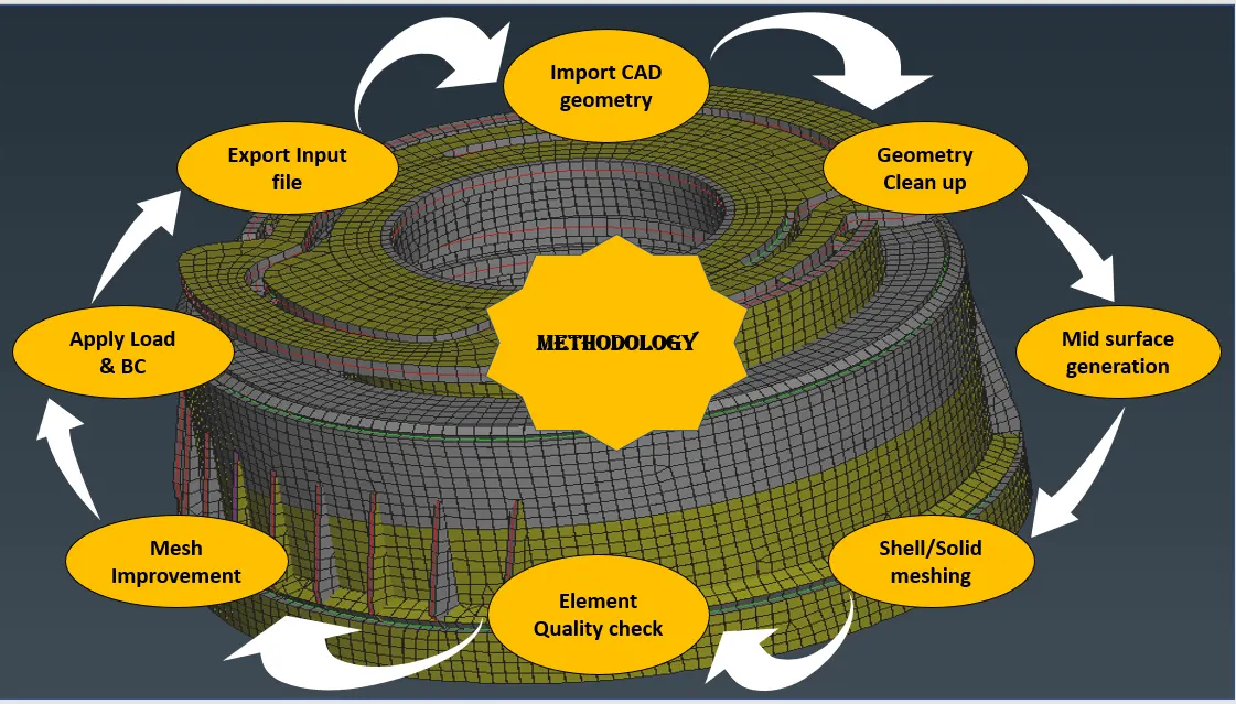
Figure 2. Methodology.
1. Import CAD geometry:
Input the given cad model. Here the given cad model is Plastic part - Bottle cap
Figure 3. Input CAD geometry.
2. Geometry cleanup:
- To generate FEM we clean up the geometry.
- Surface patch up, creating new surfaces, eleminating of triple cons in unwanted area, converting single cons to double cons in necessary area are comes under geometry cleanup phase. ANSA has some option to rebuilt the surfaces for some extent.
- By using checks manager we will check the geometry & if the error shows fix those error manually or by using autofix.
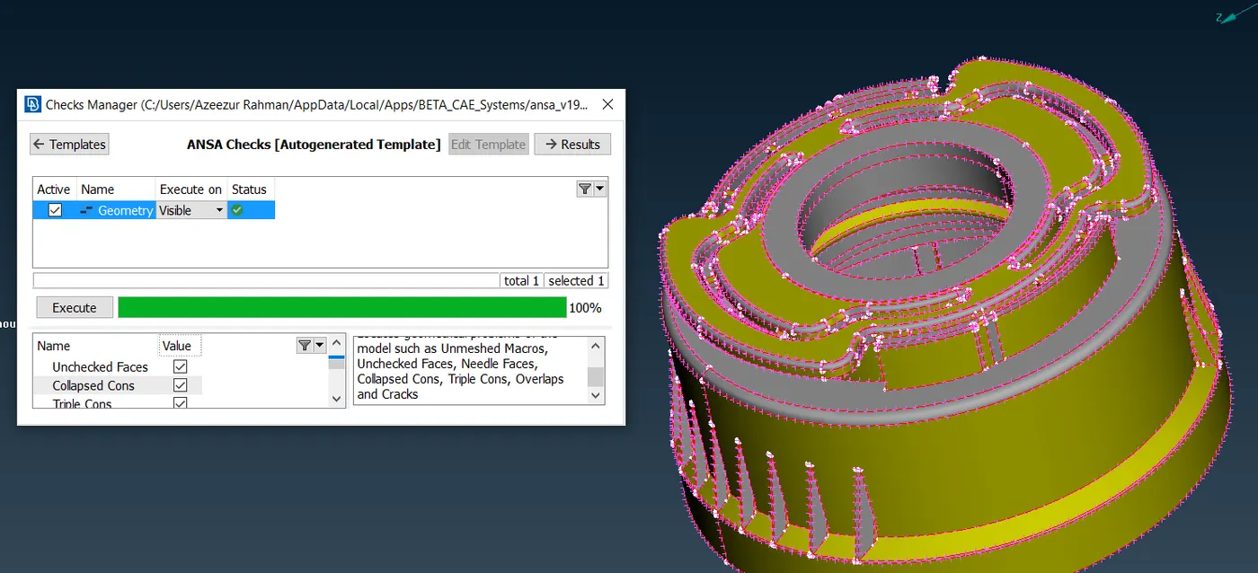
Figure 4. Geometry cleanup
3. Mid surface generation:
- This will be done once after the geometry cleanup & extraction of mid surface is an important step in CAE which has to be followed.
- Mid is the neutral pahse which is been generated from the CAD which is imported or given to us.
- The conversion of 3D cad to 2D cad is happening in mid surface generation.
- The mid surface is generated to reduce the complexity as by simplifying the cad model we get more accurate simulation results in shorter time.
- Once mid surface is extracted feed in the properties of materials & assign thickness for particular model using set PID option.
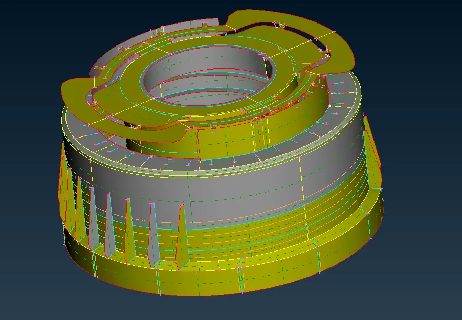
Figure 5. Mid surface of given CAD geometry.
4. Shell or solid meshing:
- Shell meshing is achieved after skin extraction but we do not mid surface all components based on requirements we should also be doing volumetric mesh.
- For casting & molding products we generally go with solid meshing.
- In this project, I have used a shell mesh for meshing the given model eventhough it is a plastic component.
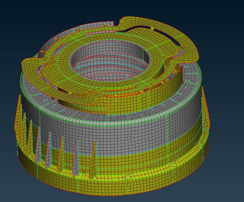
Figure 6. Generation of mesh for given CAD geometry.
5. Element quality check:
- Every product which is been produced will go through the set of quality check. If quality check fails other steps like B/C & applying loads will not be feasible, So element quality check will be performed.
- The given quality criteria values been enterd in quality manager ( shortcut key : F11). These colours are customizable and can be seen while meshing if the elements are beign failed. These failed elements should be corrected and the elements should matches the quality criteria.
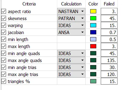
Figure 7. Quality checks.
6. Mesh Improvement:
- In this phase, the quality of FEM will be improved.
- After quality check any improvements that is been addressed that will be done in mesh improvement stage.
7. Apply load & BC: Loads & boundry conditions will be applied on this phase.
8. Export input file:
- Have to choose which software will read the file. As different solvers follow seperate algorithms & process.
- Decks: NASTRAN - NVH, PAM CRASH - Safety, LS DYNA - safety, ABAQUS - durability.
CAD TOPOLOGY:
- To run a simulation on a CAD model, the model needs to fullfil somewhat more restrictive criteria than one might be used to.
- The reason is since a mesh needs to be generated it is not enough that the CAD model just looks correct. This involves some cleaning aspects, discussed under CAD preparation but also some topological aspects.
- Here you can find some hints on them,
- For a correct & effective setup of simulation, have to make sure that the CAD model has the right topology for the simulation which wants to run.
- In general, a CAD model consists of different types of topological entities such as solids, faces, edges or vertices. Should be aware of these topologies since it will have an impact on how the mesh is generated for it.
- CAD topology is nothing but the CAD surfaces. The surfaces has to be proper to generate a FEA model.
COLOUR CODE FOR CONS:
- Single cons - Red.
- Double cons - Yellow.
- Triple cons - Cyan blue.
TOPOLOGY Vs GEOMETRY:
Topology: Describes how elements are bounded & connected.
Geometry: Describes the shape of each element.
MESHING :
- Meshing - Automated net generated.
- A mesh is a network that is formed of cells & points. It can have almost any shape in any size & is used to solve partial differential equations. Each cell of the mesh represents an individual solution of the equation which, when combined for the whole network, result in a solution for entire mesh.
- FEM allowed for mixed types of mesh cells & unstructured meshes became feasible.
- 2D - Structural mesh.
- 3D - Unstructured as well as structured mesh.
Process of Meshing:
- Definite element size.
- Choose types of element.
- Shell mesh (2D - tria & quad)
- Various methods.
- Surface less meshing.
- Solid mesh (3D - tetrahedron, hexahedron, pyramid, wedge)
- Tetra mesh ( Unstructured mesh).
- Hexa mesh ( Structured mesh).
- Quality cruteria check.
- Remesh - Quality improvement.
PROCEDURE:
- Import the cad geometry - Input the given cad model. Here the given cad model Plastic part - bottle cap. Use boolean operation tab to play with hide/unhide the neighbouring surfaces.
- Geometry cleanup - To generate FEM we clean up the geometry. Surface patch up, creating new surfaces, eleminating of triple cons in unwanted area, converting single cons to double cons in necessary area are comes under geometry cleanup phase. ANSA has some option to rebuilt the surfaces for some extent. By using checks manager we will check the geometry & if the error shows fix those error manually or by using autofix.
- Step 1: After imported the cad. Go to Checks manager > Geometry > Click Excecute to run checks manager.
- Step 2: The errors in the cad geometry will be highlighted. Now right click the highlighted errors and click fix to auto fix the errors or manually fix the error by releasing the hot points & cons. Here I have fixed the error by using autofix. Now the geometry will rerun for checks and the error will be solve.
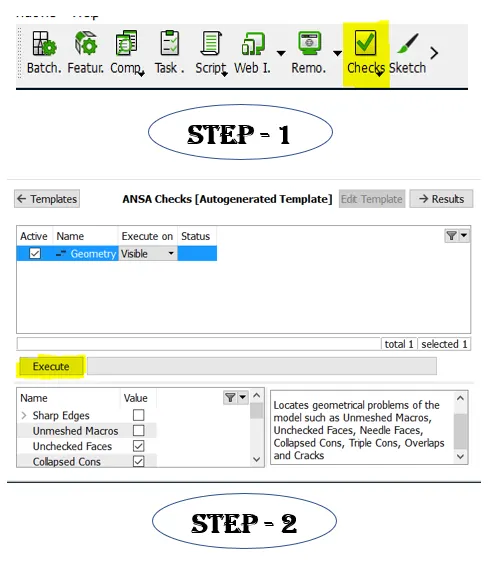
Figure 8. Steps for geometry clean up.
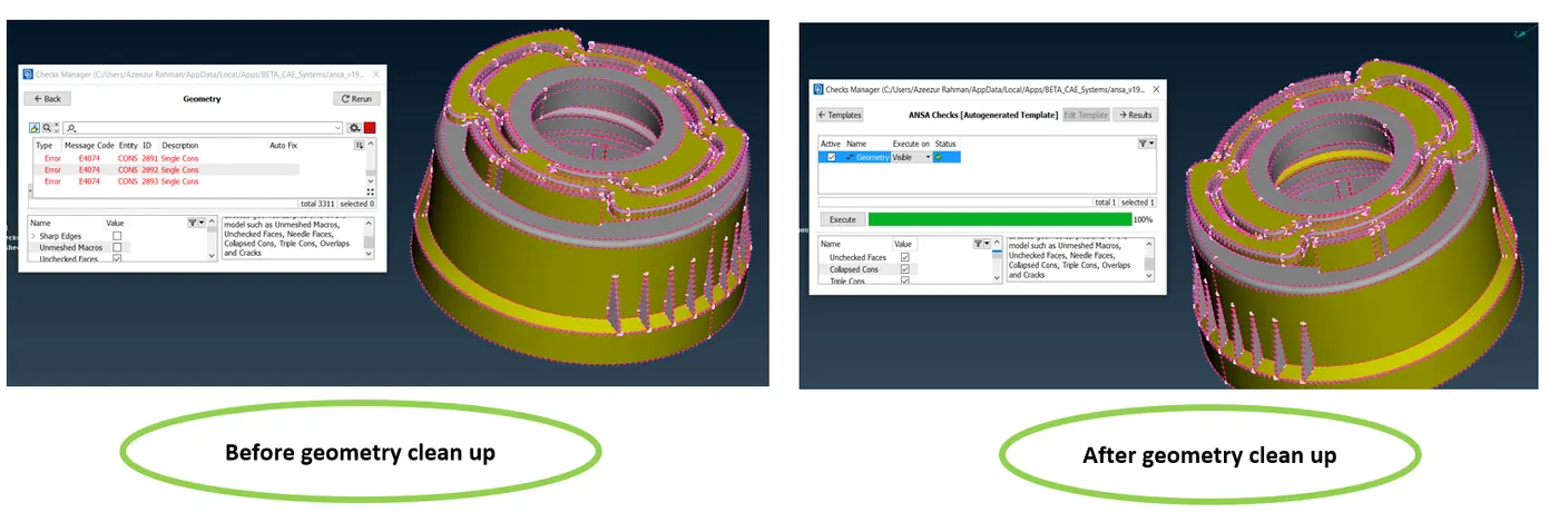
Figure 9. Before & after geometry clean up.
- Mid surface generation - Mid is the neutral pahse which is been generated from the CAD which is imported or given to us. The conversion of 3D cad to 2D cad is happening in Skin / mid surface generation. The mid surface is generated to reduce the complexity as by simplifying the cad model we get more accurate simulation results in shorter time.
- Step 1: Before mid surface generation measure the thickness of the parent geometry which is been imported. The thickness should be measured at various places by this the variation in thickness will be found. Go to measure --> Nodes --> click on any two hot points to get the value. The measured value can also been stored by clicking stored and viewed later on data base window. By clicking F12, the data window will popup.
- Step 2 (Manual - offset): In Topo module --> Faces tab --> click offset for manual skin generation & select faces and do middle click. After that enter offest value which will be the half of the thickness value of parent geometry. The value sign (+/-) should be based on orient view. In manual skin generation, PID should assign manually.
- Step 2 (Auto - mid): In Topo module --> Faces tab --> click mid surface --> cast for auto mid generation & select the entire component & middle click. Then the edit area tab will open. Now check with colours. Red - bottom surface, Blue - middle (thickness part), Green - top surface. If it is correct go a head with middle click on mouse. If not, correct the colours by using edit area tab. Here the offset value should be positive only. In auto mid generation, PID will assign automatically.
- In this challenge, I have gone with manual mid surface extraction & used offset as well as middle multi to generate a mid surface
- Step 3: Now the mid surface would generated. To check with mid surfaces. The outer entities of mid surfaces will always have a single cons (Red). If we see any cyan or yellow colour outside then the mid surface has an issue.
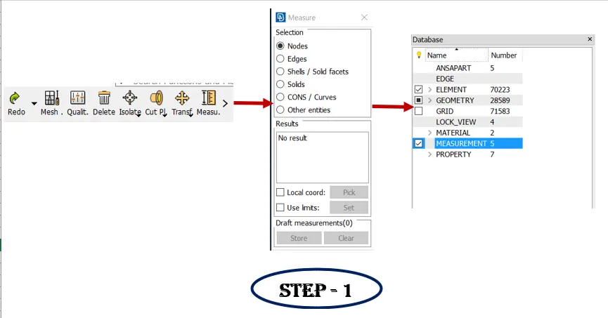
Figure 10. Mid surface generation - step 1.
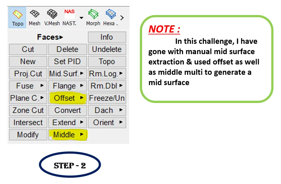
Figure 11. Mid surface generation - step 2.
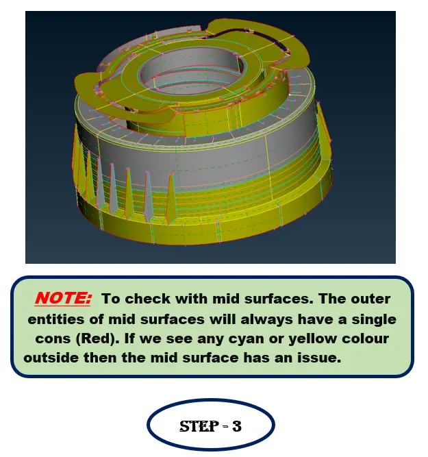
Figure 12. Midsurface of BOTTLE CAP (Step -3).
- Assign PID - For manual mid generation PID has to assign manually. For auto mid generation (Skin/cast) PID & thickness will be assigned automatically.
- Step 1: Go to topo module --> Faces --> Set PID --> Faces/shells (In selection window) ---> select the mid surface geometry --> Now property window will open & the PID will be created for the mid surface.
- Step 2: Assign thickness in thickness tab (T)
- Since it is a plastic part there will be a varrying thickness. For parts having varying thickness the average thickness can be given or multiple thickness can be given for a part by assigning seperate PID to the same parts.
- In this challenge, I have gone by taking average thickness for the ribs having varrying thickness.
- Avg thickness = (Max. thickness + Min. thickness) / 2
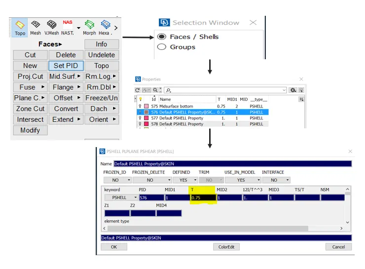
Figure 13. Steps to assign PID & thickness.
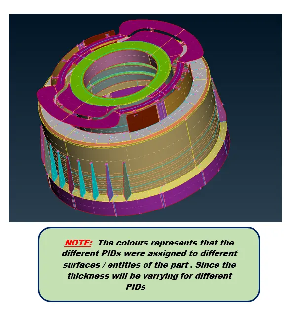
Figure 14. Assigned PID
- Quality criteria - Every product which is been produced will go through the set of quality check. If quality check fails other steps like B/C & applying loads will not be feasible, So element quality check will be performed. The given quality criteria values been enterd in quality manager ( shortcut key : F11). These colours are customizable and can be seen while meshing if the elements are beign failed. These failed elements should be corrected and the elements should matches the quality criteria.
- Step 1: To enter the given quality criteria values Click quality criteria / press F11 to open quality criteria window (for shortcut) --> Quality criteria window will open. In shells Enter the given quality value to the particular tab and edit the colours for the better visualization of quality failure.
- Step 2: Apply. Then save the quality criteria value and import it while reopening the file.
- Step 3: Go to presentation parameters as shown in the below figure. There under Graphics --> select Enable %.
- Step 4: And also under detail & demand effect slide the curser to all details as shown in the below figure.
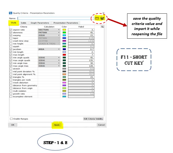
Figure 15. Quality criteria - Steps 1 & 2.
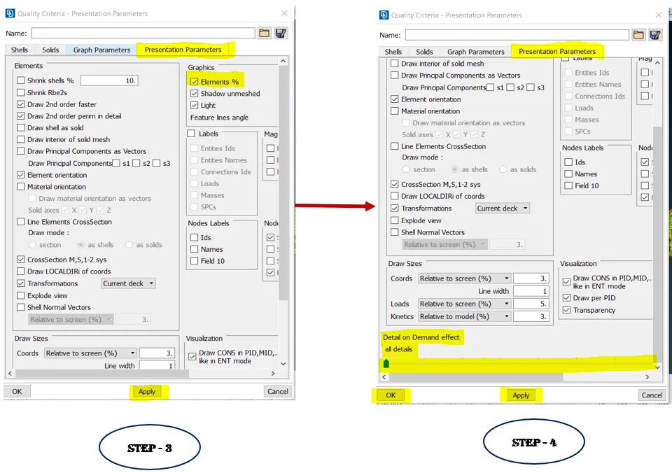
Figure 16. Quality criteria - Steps 3 & 4.
- Set mesh parameter - Mesh parameters is nothing but defining the meshing parameters. Once assiging the qulaity value mesh parameter has to be set. For that Go to Mesh parameter --> Enter target length, Min. target length & Max. target length. Check the parameters highlighted in yellow colour as the below given figure before giving OK
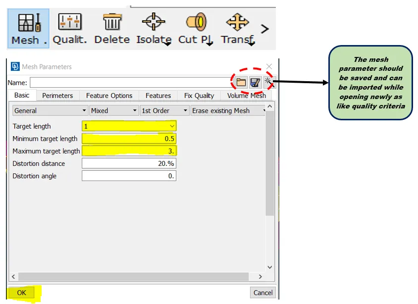
Figure 17. Mesh parameter
- Mesh module ( Before meshing) - A mesh is a network that is formed of cells & points. It can have almost any shape in any size & is used to solve partial differential equations. Each cell of the mesh represents an individual solution of the equation which, when combined for the whole network, result in a solution for entire mesh.
- Step 1: Go to mesh module from topo module. In mesh module, we can see all the cons will be in green & hot points as white points.
- Step 2: Measure the perimeter length - GO to perimeter --> Length ( selection window will be open) --> select perimeter --> select the entire mid surface geometry & click middle on mouse ( length parameter tab will be open) --> enter the target value in the length tab --> OK.
- Step 3: Defeaturing - In CAD setup defeaturing plays a vital role. Defeaturing is nothing but to remove the unnecessary surface radius, holes, edges. Often, your CAD model does containmany detailed features because of manufacturing constraints. Very small entities can be a problem. If you have very small faces with sharp angles the surface meshing might fails for qulaity. Therefore, check your CAD model for very small entities and remove them before trying to create a mesh for it.
- Step 4: Split the Macro area (using Macros --> cut) to get better mesh flow. Also remove those cut lines after meshing (using Macros --> join).
- Meshing - Automated net generated.
- Step 1: To generate mesh - GO to Mesh generation --> best --> select the surfaces to be meshed & middle click the mouse to confirm. Now the mesh will be generated on the selected surfaces.
- Step 2: Quality check - To get visibility of quality failure. Go to hidden mode from shadow mode.
- Step 3: If any elements fails for quality then play with shell mesh tab (Resconstruct & smooth option), Elements tab (split, join, swap option), Grids tab (Move & paste option) to meet the quality criteria. Those option will mostly helps to resolve the quality failure of the elements. Some of the examples for the above mentioned options used in this projects are represented with a picture below.
- Step 4: Elimination of trias - Mostly the trias should be eliminated whereever possible.
- Two opposite trias should be eliminated.
- Tria element should not lies on perimeter line.
- Nearer trias must carried out to some extent.
- To achieve above three points in step 4. Split, swap, join, paste options can be used.
- Split - Used to split the quads to tria elements. Also split is used to carry out the trias in forward direction.
- Join - Used to remove the two tria elements to make/merge as quad element.
- Swap - To move the trias which lies on the perimeter swap can be used. Swap is used to carry out the trias up & downward direction.
- Paste - It is used to carryout the trias towards backward direction.
- After these split, join, swap, paste option smooth must be performed without fail for good mesh flow.
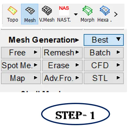
Figure 18. STEP 1 to perform best mesh.
Figure 19. Picture of Best mesh elements.
Figure 20. Shows the shadow & hidden mode.
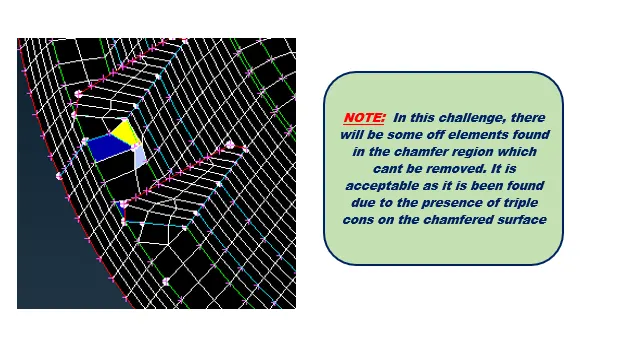
Figure 21. Shows some quality fails after meshing
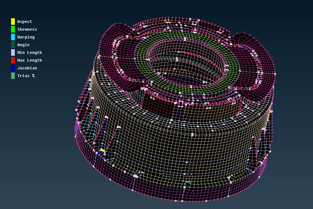
Figure 22. Meshed geometry.
- Draw shell as solid - Draw shell as solid should be activated after finishing challenge. Since it is a shell elements, After activating draw shell as solid the meshed shell elements will convert to solid, by considering the thickness assigned on PID. This is a final stage in this week-4 challenge which has to done before submiting.
- Step 1: Go to Quality criteria (short cut key - F11) -->presentation parameters --> Select Draw shell as solid ---> OK
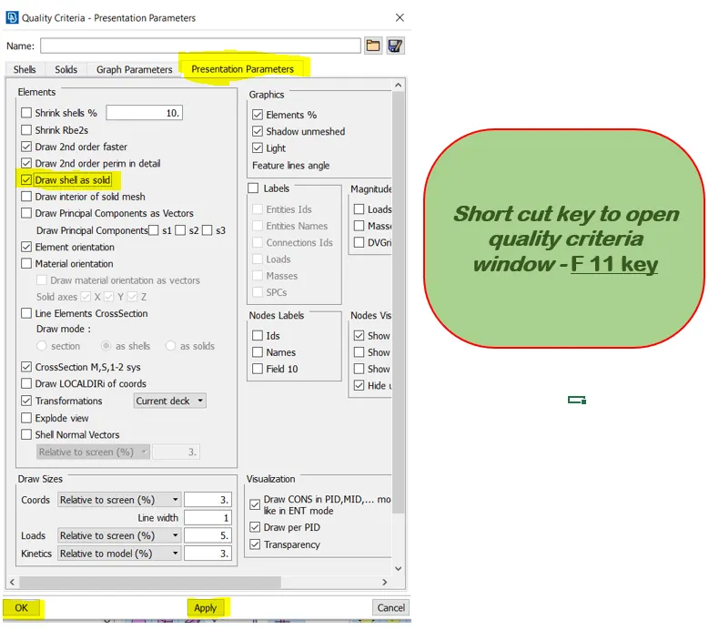
Figure 23. Steps to select draw shell as solid.
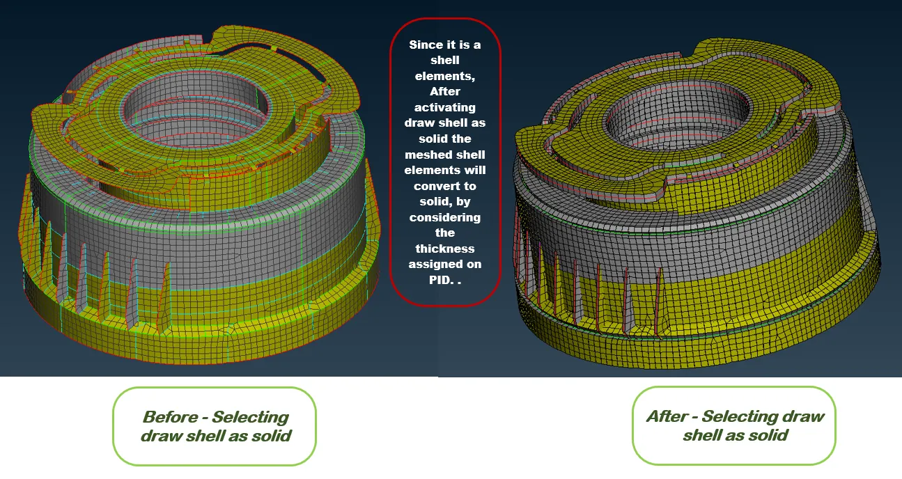
Figure 24. Shows the differences before & after selecting draw shell as solid
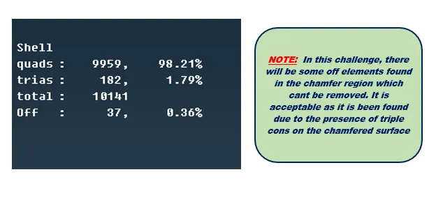
Figure 25. Details of elements
LEARNING OUTCOMES :
At the end of this challenge, I can able to
- Perform geometry cleanup for any complex plastic components.
- Generate midsurface with a flow for any complex plastic components.
- Generate shell mesh meeting the given quality criteria for any complex plastic components.
- Identify the quality failure and resolve the failure & improve the mesh quality.
- Work on ANSA with a flow.
CONCLUSION :
Hence, the geometrical errors and mesh, with the given element Quality criteria has been performed successfuly for a given plastic component. Also after meshing the component thickness has been assigned. As per methodology, From import cad, geometry clean up to mesh improvement phases have been performed successfuly. The Applying load & Boundry condition phases will be performed on upcoming challenges.