Performance analysis of beam under load
Aim: To compare the performance of three types of beams under a bending load
Objective:
- To compare the bending performance in beams with different cross-section under bending load using Solidwork:
- Rectagular-section beam
- I-section beam
- C-section beam
- To generate plots for:
- Von Mises Stresses
- Strain
- Displacement
Introduction
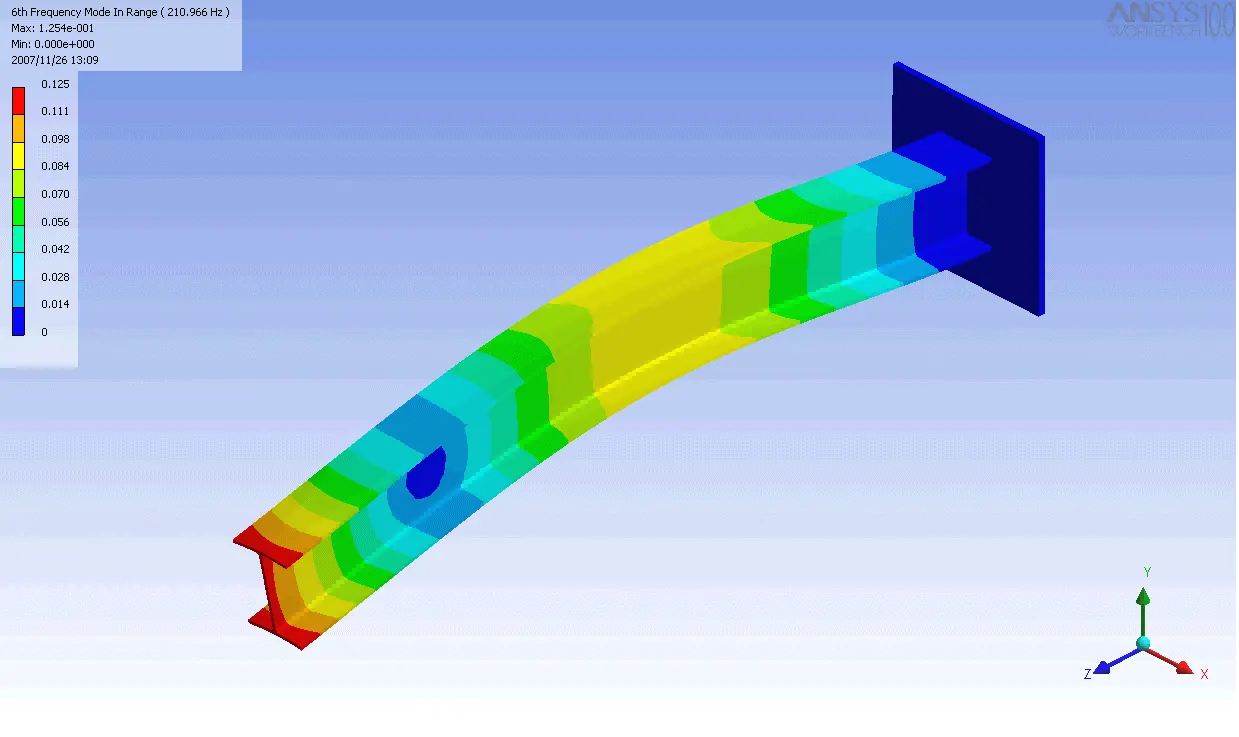
Finite element analysis
- Finite Element Analysis or FEA is the simulation of a physical phenomenon using a numerical mathematic technique referred to as the Finite Element Method, or FEM. This process is at the core of mechanical engineering, as well as a variety of other disciplines. It also is one of the key principles used in the development of simulation software. Engineers can use these FEM to reduce the number of physical prototypes and run virtual experiments to optimize their designs.
- Complex mathematics is required in order to understand the physical phenomena that occur all around us. These include things like fluid dynamics, wave propagation, and thermal analysis.
- Analyzing most of these phenomena can be done using partial differential equations, but in complex situations where multiple highly variable equations are needed, Finite Element Analysis is the leading mathematical technique.
Bending of Beams
- In applied mechanics, bending (also known as flexure) characterizes the behavior of a slender structural element subjected to an external load applied perpendicularly to a longitudinal axis of the element.
Stress and Strain
Stress is defined as a force applied per unit area. The unit of stress is N/m2.Stress applied to a material can be of two types. They are:
- Tensile Stress: It is the force applied per unit area which results in the increase in length (or area) of a body. Objects under tensile stress become thinner and longer.
- Compressive Stress: It is the force applied per unit area which results in the decrease in length (or area) of a body. The object under compressive stress becomes thicker and shorter.
The strain is the amount of deformation experienced by the body in the direction of force applied, divided by initial dimensions of the body. The strain is a dimensionless quantity as it just defines the relative change in shape. Depending on stress application, strain experienced in a body can be of two types. They are:
- Tensile Strain: It is the change in length (or area) of a body due to the application of tensile stress.
- Compressive Strain: It is the change in length (or area) of a body due to the application of compressive strain
Stress-Strain curve
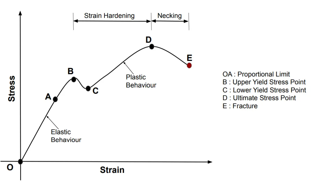
A stress–strain curve for a material gives the relationship between stress and strain. It is obtained by gradually applying load to a test coupon and measuring the deformation, from which the stress and strain can be determined. These curves reveal many of the properties of a material such as the Young's modulus, the yield strength and the ultimate tensile strength.
- Proportional Limit
- It is the region in the stress-strain curve that obeys the Hooke’s Law. In this limit, the ratio of stress with strain gives us proportionality constant known as young’s modulus. The point OA in the graph is called the proportional limit.
- Elastic Limit
- It is the point in the graph up to which the material returns to its original position when the load acting on it is completely removed. Beyond this limit, the material doesn’t return to its original position and a plastic deformation starts to appear in it.
- Yield Point
- The yield point is defined as the point at which the material starts to deform plastically. After the yield point is passed, permanent plastic deformation occurs. There are two yield points (i) upper yield point (ii) lower yield point.
- Ultimate Stress Point
- It is a point that represents the maximum stress that a material can endure before failure. Beyond this point, failure occurs.
- Fracture or Breaking Point
- It is the point in the stress-strain curve at which the failure of the material takes place.
Procedure
- Create a 3D model of three types of beams i.e. rectangular beam, I-section beam, and C-section beam and save them separately.
- Now for doing the simulation, click on ‘Simulation’ and then select ‘New Study’ and then ‘Static’ for static study.
- Now apply a material to beam that is Alloy steel for all the beams by right clicking on the part name and then on ‘Apply/Edit Material’.
- Now for fixing the beam at one end, this will enable the beam to be treated as a cantilever beam, right click on ‘Fixtures’ option and then on ‘Fixed Geometry’ option, then select the face that is to be fixed.
- Now for providing load right click on external loads option and select ‘Force’ option now select the face for normal force and then set the force to be 1500 N.
- Now for creating a mesh, right click on ‘Mesh’ them on ‘Create Mesh’ now use the ‘Mesh Parameters’ option then enter the size of mesh as fine.
- Now click on 'Run this study' on the top menu bar for running the simulation.
Model geometry and inputs
Rectangular Beam
I-section Beam
C-section Beam
3D Models
Rectangular Beam and meshing
I-section Beam and meshing
C-section Beam and meshing
Results
Rectangular Beam
Displacement plot
Strain plot
Stress plot
I-section Beam
Displacement plot
Strain plot
Stress plot
C-section Beam
Displacement plot
Strain plot
Stress plot
TABULATED RESULTS
|
Sl. No |
Description |
Rectangular Beam |
I-beam |
C-beam |
|
1 |
Yield Strength (N/mm2) |
6.204 X 10⁸ |
6.204 X 10⁸ |
6.204 X 10⁸ |
|
2 |
Max. Von Mises Stresses (N/mm2) |
6.643 X 10⁷ |
2.6089 X 10⁷ |
4.7895 X 10⁷ |
|
3 |
Max. Strain (no unit) |
2.903 X 10⁻⁵ |
8.148 X 10⁻⁵ |
1.62 X 10⁻⁴ |
|
4 |
Max. Displacement (mm) |
0.031 |
0.083 |
0.304 |
|
5 |
Mass (g) |
11088.00 |
2238.22 |
3222.66 |
OBSERVATIONS:
- In rectangular beam we can see that the maximum Von Mises Stress is 6.643 X 10⁷ N/mm2 and maximum displacement is 0.031 mm that is smallest amongst all the three cases. This is the advantage of using a rectangular beam as it can bear a large amount of load and the deflection generated is also very less but the downside of rectangular beam is that it is the heaviest among all the three cases which makes it less useful as the material used is more and due to which the cost of using the beam also increases. Therefore this type of beam not used generally and is not the best beam type.
- In C – section beam we can see that the maximum Von Mises stress is 4.7895 X 10⁷N/mm2and the maximum displacement is 0.304 mm which is the highest amongst all the three cases. This states that it does not have a high value when it comes to the structural integrity of the beam. Therefore this type of beam is also not used as the stress induced is very high due to which the deflection is also high.
- In I – section beam we can see that the maximum Von Mises stress is 2.6089 X 10⁷ N/mm2 and the maximum displacement of deflection is 0.083 mm which is in between the other two cases. This makes it the best beam configuration as in this type of beam the material used is also less and it still it can bear a high value of stress without much deflection. Due to less material used the overall cost of using this type of beam is also less as compared to rectangular beam.
- We can say that when considering all the economical, commercial and structural aspects of all the three types of beams, I – section beam is the best type of beam amongst all the three beams.
CONCLUSION
Using the above steps, we were able to compare the performance of three types of beams under a bending load