MBD Simulation on a Piston Assembly using Solidworks
MBD Simulation on a Piston Assembly
AIM: To create a 3D model and assemble the parts of a Piston Assembly and then perform a multi body simulation on the system
OBJECTIVE:
The main objective of this simulation is to plot a Linear Displacement vs Time graph based on the conditions given below:-
| Sl.No |
Wrist Pin Offset |
Crank Speed (RPM) |
| 1 | 0 mm | 2000 |
| 2 | 10 mm Positive | 2000 |
| 3 | 10 mm Negative | 2000 |
INTRODUCTION
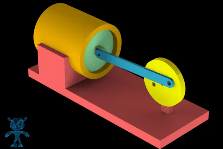
Internal combustion engines are seen every day in automobiles, trucks, and buses. The name internal combustion refers also to gas turbines except that the name is usually applied to reciprocating internal combustion (I.C.) engines like the ones found in everyday automobiles. Spark ignition engines take a mixture of fuel and air, compress it, and ignite it using a spark plug. The name `reciprocating' is given because of the motion that the crank mechanism goes through. The piston cylinder engine is basically a crankslider mechanism, where the slider is the piston in this case. The piston is moved up and down by the rotary motion of the two arms or links. The crankshaft rotates which makes the two links rotate. The piston is encapsulated within a combustion chamber. The bore is the diameter of the chamber. The valves on top represent induction and exhaust valves necessary for the intake of an air-fuel mixture and exhaust of chamber residuals. In a spark ignition engine a spark plug is required to transfer an electrical discharge to ignite the mixture.
PART MODELS
PISTON HEAD
The piston head is the top surface (closest to the cylinder head) of the piston which is subjected to tremendous forces and heat during normal engine operation. A piston pin bore is a through hole in the side of the piston perpendicular to piston travel that receives the piston pin.
CONNECTING ROD
A connecting rod, also called a con rod, is the part of a piston engine which connects the piston to the crankshaft. Together with the crank, the connecting rod converts the reciprocating motion of the piston into the rotation of the crankshaft.
END CAP
The end cap is the extended part (can be assembled with a connecting rod by threaded bolts) of the connecting rod and it can be designed with the connecting rod dimensions.
GUDGEON PIN
A pin holding a piston rod and a connecting rod together by connecting both of them.
CRANK
When combined with a connecting rod, a crank can be used to convert circular motion into reciprocating motion, or vice versa.
COMPLETE MODEL OF PISTON ASSEMBLY
LINK FOR PARTS:
https://drive.google.com/open?id=1DSNy13Vhnu-Fft5NaINsNnvhYE4dcGyo
ANIMATION OF THE PISTON ASSEMBLY
PROCEDURE
- Select the SolidWorks Motion from SolidWorks Add-Ins in the ribbon.
- Select motion analysis from the drop-down menu available in the motion analysis toolbar.
- All the tools mentioned below can be availed from the motion analysis toolbar.
- Provide the motor condition i.e. rotary with 2000 rpm.
- Provide all the solid body contacts separately and also assign material to the solid bodies.
- Provide gravity in the -y axis i.e. in the downward direction.
- Select Motion Study Properties and increase the frames to 12,000 to capture the displacement for single degree rotation and checkmark the precise contact option. Number of frames required was calculated as (2000*360)/60 = 12000.
RESULTS AND PLOTS
1) No offset
2) -10mm offset
3) +10 mm offset
EXPLANATION
The graphs obtained above, we can observe that linear displacement increases slightly as the offset moves from negative to positive. This inturn means that the magnitude of linear displacement also increases as the the offset moves from negative to positive.
RESULTS AND CONCLUSION:
| No offset | +10mm offset | -10 mm offset | |
| Displacement at t=0 | 322.446262351309 | 322.32940505668 | 322.419917519419 |
| Displacement at t=0.2 | 246.172287436018 | 244.218540081039 | 248.068823647987 |
| Displacement | 76.274 | 78.1109 | 74.351094 |
Max displacement: Positive offset
Min displacement: Negative offset