Otto cycle - Air standard Cycle
AIM:
To Write code on solve an otto cycle and make plots for it.
- create a PV diagram
- Find the thermal efficiency of the engine.
OTTO CYCLE:
basicaly the otto cycle are four strokes. Otto cycle is based on IC engine are petrol engine.there is contain six stroke but 2 strokes are mechanical rotation .So the is 4 main strokes. Otto cycle is based on IC engine are petrol engine.also thre is called as a spark - ignition engine .
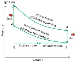
1 TO 2 : is a isentropic compresssion process. [p.v^gamma = constant]
2 TO 3 : is a constant volume Heat- addition process.[p/t = constant]
3 TO 4 : is a isentropic expanssion process. [p.v^gamma=constant]
4 TO 1 : is a constant volume Heat-Rejection process. .[p/t = constant]
i workout the program to find the p-v diagram on a otto cycyle. And also calculate the thermal efficiency.
`p2v2^gamma=p1v1^gamma`
`p2=p1*(cr)^gamma`
`t2=t1*(cr)^(gamma-1)`
p= pressure (pa) ; v=volume (m^3); cr= compression ratio; t=temperature (k) ; R = ratio of the length of connecting rod to the crank pin radius;
a= crank pin radius; gamma = specific Heat ratio
clear all
close all
clc
bore = 0.1; % bore (m) ia inner diameter of the cylinder
stroke =0.1; % stroke (m) is piston move BDC to TDC
cr=12; % cr = v1/v2
con_rod =0.15; % length of a conecting rod(m)
v_s =pi/4*bore^2*stroke; % Swept volume is the piston move TDC toBDC(displacment volume)
v_c = v_s/(cr-1); % v_c is a clerance volume there equal to v2
%inputs
gamma = 1.4; %specific Heat ratio
% STATE VARIABLE 1
v1 = v_s +v_c; % total volume of the piston
p1 = 101325; % Stanterd air pressure At state point 1 (IS GIVEN INPUT)
t1 = 500; % Temperature At the state point 1 (is given input)
v2 = v_c; % v2 is Equal to clerance volume
% STATE VARIABLES AT POINT 2
% p2v2^gamma =p1v1^gamma
% p2 = p1*(v1/v2)^gamma = p1*cr^gamma
p2 =p1*cr^gamma; % Pressure At State point 2
% t2=t1*cr^(gamma-1)
t2 = p2*v2*t1/(p1*v1); % Temperature At the state point 2
% STATE VARIABLE AT THE POINT 3
v3=v2; % there is CONSTANT VOLUME HEAT ADD PROCESS
t3 = 2300;
p3 = p2*t3/t2;
% STATE VARIABLE AT POINT 4
v4 = v1; % thete is a CONSTANT VOLUME HEAT REJECTION PROCESS % t4=t3*cr^(1-gamma)
p4 = p3*(v3/v4)^gamma;
t4 = t3*cr^(1-gamma);
% PLOTING OF GRAPH
figure(1)
hold on
plot(v1,p1,'*','Color','r') % There is state variable at point 1
plot(v2,p2,'*','Color','r') % There is state variable at point 2
plot(v3,p3,'*','Color','r') % There is state variable at point 3
plot(v4,p4,'*','Color','r') % There is state variable at point 4
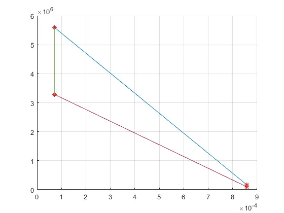
plot([v2,v3],[p2,p3]) % there is a curve of constant volume heat-addition
plot([v4,v1],[p4,p1]) % there is a curve of constant volume heat-Rejection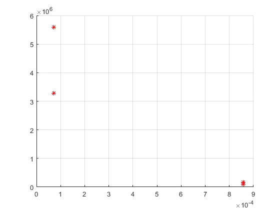
And connect the point's on
function [V] = engine_kinematics_1(bore, stroke, con_rod, cr, start_crank, end_crank)
a=stroke/2 ; % crank pin radius
R=con_rod/a ; % ratio of the length of connecting rod to the crank pin radius
v_s = pi/4*bore^2*stroke; % Calculaction of the SWEPT VOLUME
v_c = v_s/(cr-1); % Calculaction of the CLERANCE VOLUME
theta = linspace(0,180,180); % calculating the THETA VALUE
term1 =0.5*(cr-1); % Defind trem 1 of the characteridtic eqaction
term2 = R +1 -cosd(theta); % Defind trem 2 of the characteridtic eqaction
term3 = (R^2 -sind(theta).^2).^0.5; % Defind trem 3 of the characteridtic eqaction
V = (1+term1*(term2-term3)).*v_c ; % calculaction of volume
endMAIN PROGRAM :
clear all
close all
clc
bore = 0.1; % bore (m) ia inner diameter of the cylinder
stroke =0.1; % stroke (m) is piston move BDC to TDC
cr=12;   % cr = v1/v2
con_rod =0.15;  % length of a conecting rod(m)

R = con_rod/(bore/2); % R is a dimanction ratio of the crank pin
v_s =pi/4*bore^2*stroke; % Swept volume is the piston move TDC toBDC(displacment volume)
v_c = v_s/(cr-1);  % v_c is a clerance volume there equal to v2

%inputs
gamma = 1.4;

% STATE VARIABLE 1
v1 = v_s +v_c; % total volume of the piston
p1 = 101325;   % Stanterd air pressure At state point 1 (IS GIVEN INPUT)
t1 = 500;      % Temperature At the state point 1 (is given input)
v2 = v_c;      % v2 is Equal to clerance volume


% STATE VARIABLES AT POINT 2
% p2v2^gamma =p1v1^gamma
% p2 = p1*(v1/v2)^gamma = p1*cr^gamma

p2 =p1*cr^gamma; % Pressure At State point 2

% t2=t1*cr^(gamma-1)

t2 = p2*v2*t1/(p1*v1);   % Temperature At the state point 2


constant_c = p1*v1^gamma; % calculating instantaneous pressure
v_compression = engine_kinematics_1(bore,stroke,con_rod,cr,180,0); % function of engine kinematics
p_compression = constant_c./v_compression.^gamma;  % pressure value obtained


% STATE VARIABLE AT THE POINT 3
v3=v2; % there is CONSTANT VOLUME HEAT ADD PROCESS
t3 = 2300;
p3 = p2*t3/t2;


constant_c = p3*v3^gamma; % calculating instantaneous pressure
v_expansion = engine_kinematics_1(bore,stroke,con_rod,cr,0,180); % function of engine kinematics
p_expansion = constant_c./v_expansion.^gamma; % pressure value obtained

% STATE VARIABLE AT POINT 4
v4 = v1; % thete is a CONSTANT VOLUME HEAT REJECTION PROCESS  % t4=t3*cr^(1-gamma)
p4 = p3*(v3/v4)^gamma;
t4 = t3*cr^(1-gamma);


% PLOTING OF GRAPH

hold on


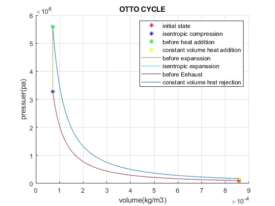
plot(v1,p1,'*','Color','r') % There is state variable at point 1
plot(v2,p2,'*','Color','b') % There is state variable at point 2
plot(v3,p3,'*','Color','g') % There is state variable at point 3
plot(v4,p4,'*','Color','y') % There is state variable at point 4


plot([v2,v3],[p2,p3]) % curve of constant volume Heat-Addition
plot([v4,v1],[p4,p1]) % curve of constant volume Heat-Rejection

plot(v_compression,p_compression) % curve of Isentropic compression
plot(v_expansion,p_expansion)   % curve of Isentropic expanssion
xlabel('volume(kg/m3)') % xlabel call volume
ylabel('pressuer(pa)') % ylabel call pressure
legend("initial state","isentropic compression","before heat addition","constant volume heat addition","before expanssion","isentropic expanssion","before Eehaust","constant volume hrat rejection") % for labeling curve
title("OTTO CYCLE")

grid on


% Thermal effiencr (or) ENGINE EFFIENCY
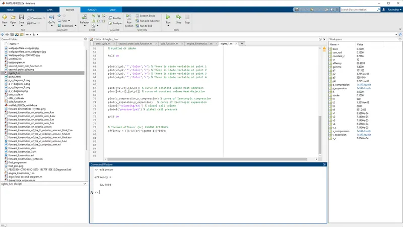
efficiency = ((1-(1/(cr)^(gamma-1)))*100);
RESULT:
CONCLUSION :
- THE Matlab Program is Successful COMPLIED
- THE P-V Diagram For the Otto cycle was successfully plotted
- THE THERMAL EFFICIENCY IS 62.9893 %
- THE Efficiency is Depends on Compression Ratio. So the Compression Ratio is incress.it's Also incressyhe Efficiency .