NX modelling - Butterfly Valve Assembly applying GD&T
Your Answers
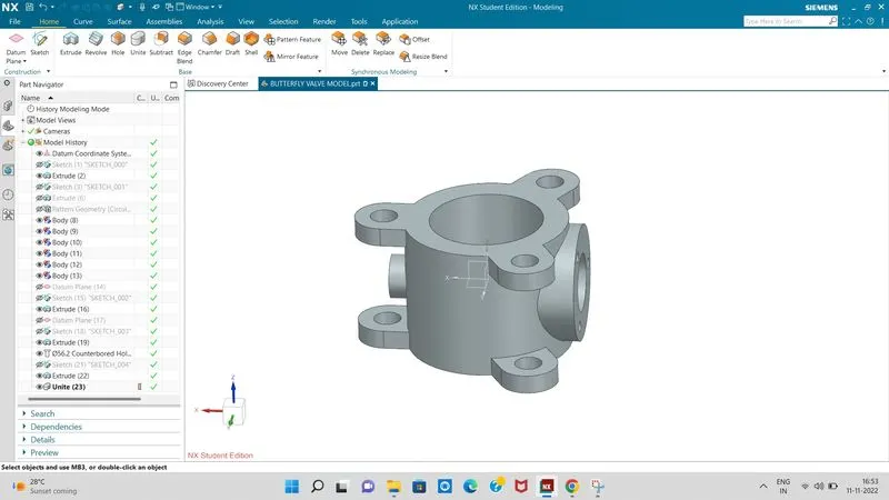
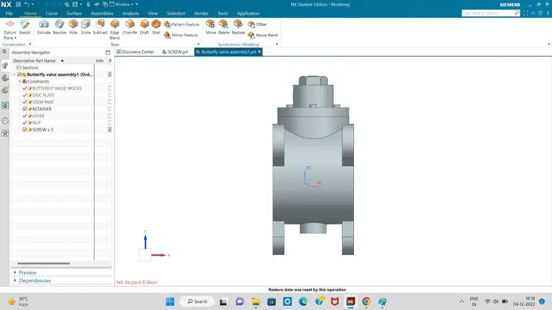
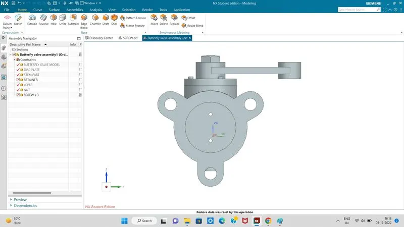
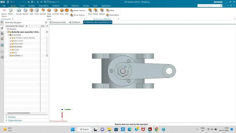
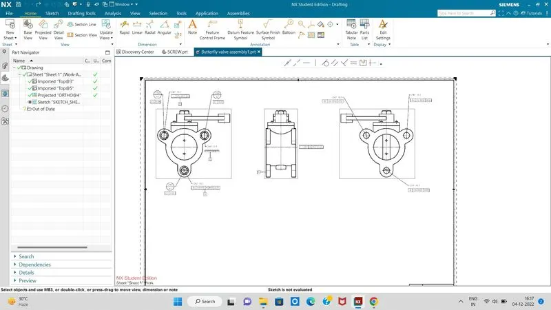
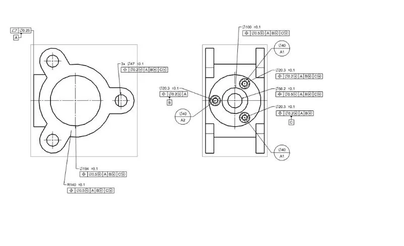
1. BODY - BUTTERFLY VALVE
Butterfly valves are usually fixed between two pipleines using flange couplings. Body of our Butterfly valve and GD&T applied to the same using Siemens NX CAD. following design rules and considerations we first draw the butterfly body.
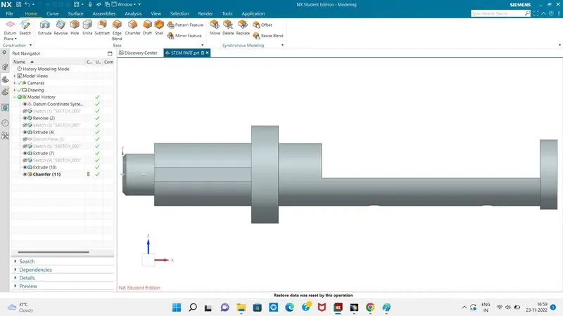
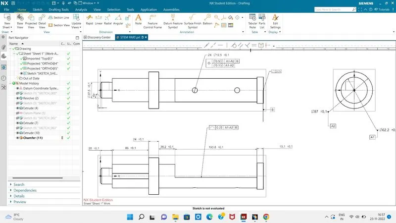
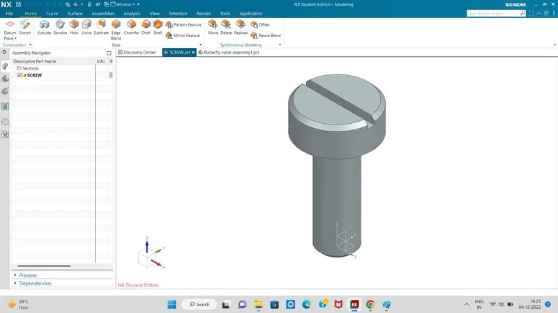
2. SHAFT - BUTTERFLY VALVE
The disc/plate, lever and nut are assembled to this shaft. following design rules and considerations we next draw the shaft body.
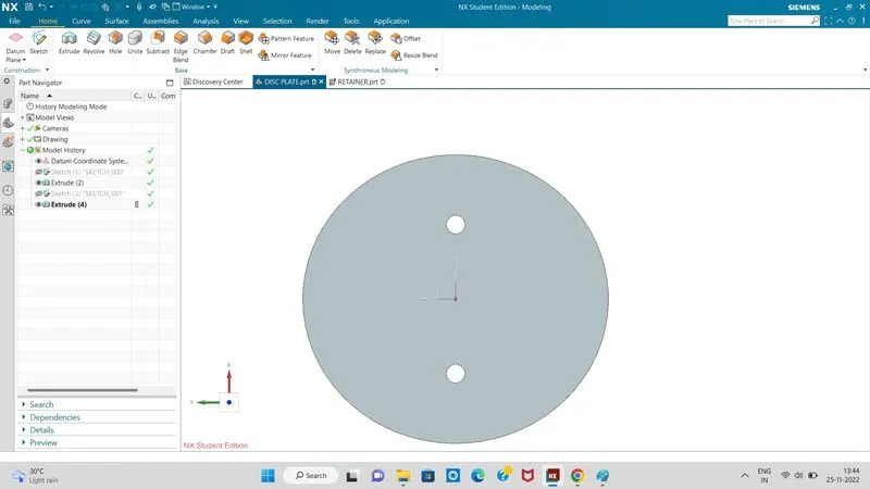
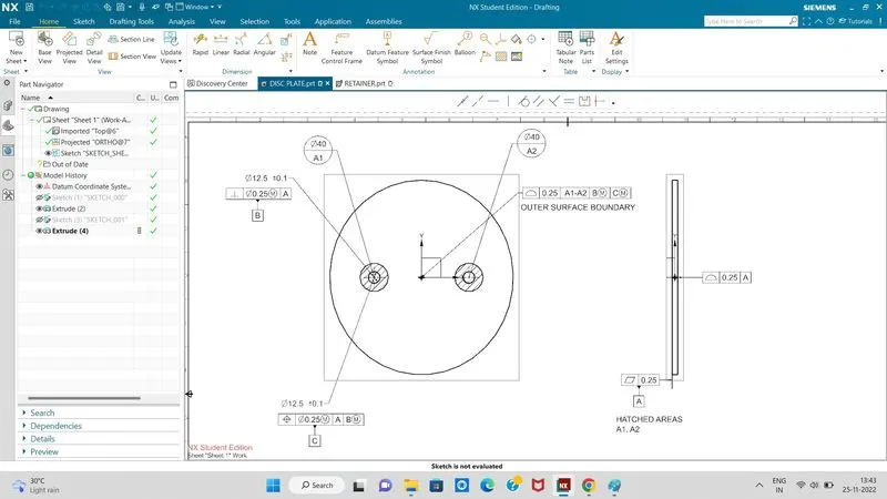
3. DISC - BUTTERFLY VALVE
When valve is fully opened or closed the disc is rotated a quarter turn.Disc is mounted on shaft.
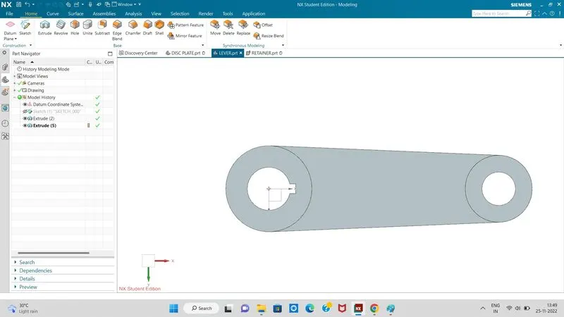
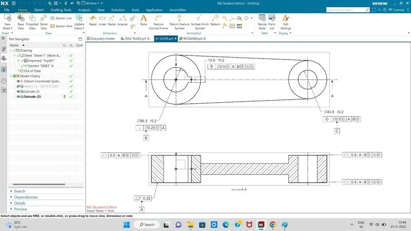
4. LEVER - BUTTERFLY VALVE
Lever is mounted at an end of shaft outside the body. Hand lever is usually used in small sized Butterfly valves. It is used to open or close the valve.
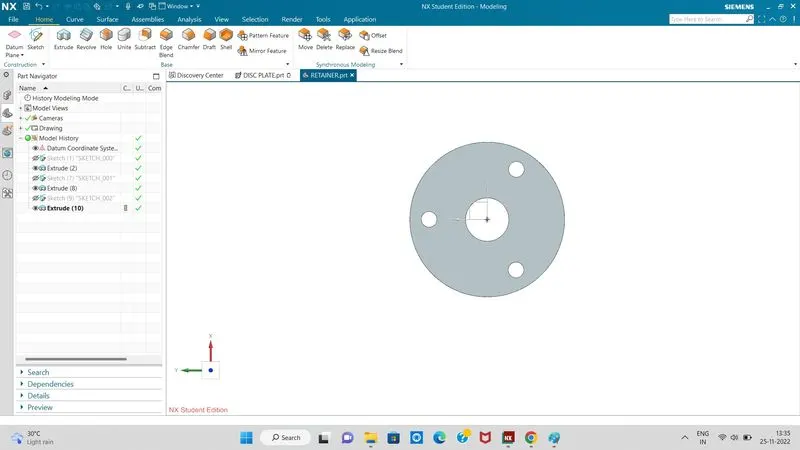
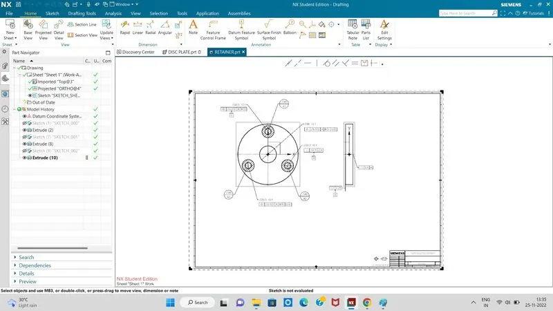
5. RETAINER - BUTTERFLY VALVE
Retainer is a kind of washer fixed on the body of butterfly valve.
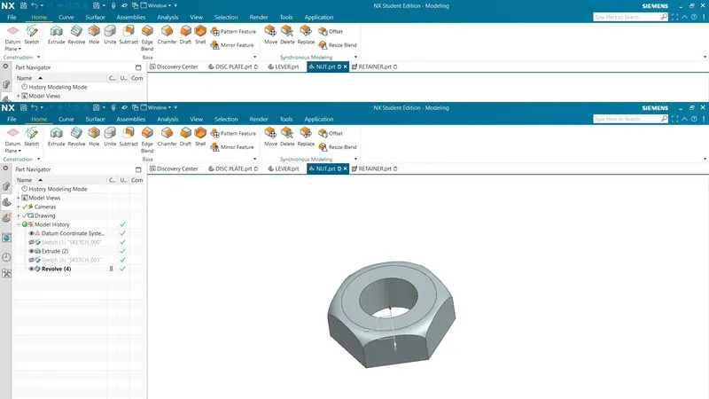
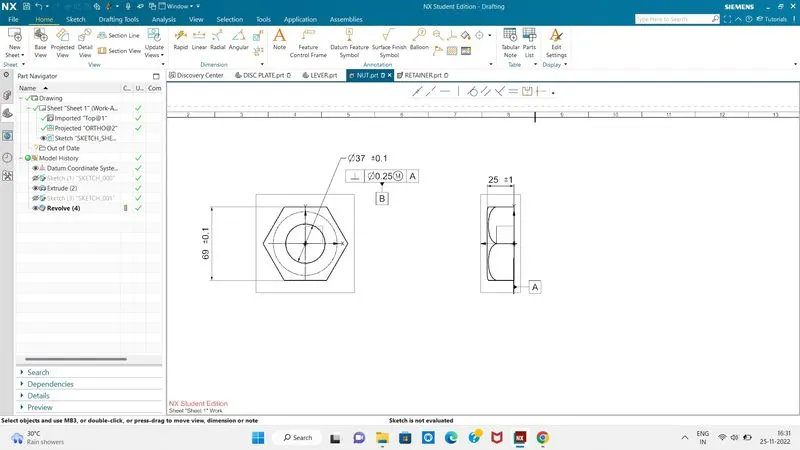
6. NUT - BUTTERFLY VALVE
It is fixed at the top end of shaft to keep the lever and retainer on position relative to the body of butterfly valve.
ASSEMBLY - BUTTERFLY VALVE
After completing the modelling of various components of butterfly valve, all parts were assembled together using Siemens NX Assembly workbench.
CONCLUSION
Butterfly valve was successfully designed and GD&T applied to all parts and the assembly of the Butterfly valve.