Multi-phase flow simulation of gearbox lubricant sloshing effect
Aim:-> To perform gearbox lubrication fluid sloshing simulation using user defined function (UDF) in ANSYS Fluent.
Theory:-
Lubrication:-
Friction is the force that resists relative motion between two bodies in contact. If friction didn’t exist, nothing would ever stop moving. We need friction to function, but there are instances where you want to be able to reduce the amount of friction present. Here comes lubrication in image. So lubrication is the process to control friction and wear by the introduction of a friction-reducing film between moving surfaces in contact. The lubricant used can be a fluid, solid, or plastic substance.
Many different substances can be used to lubricate a surface. Oil and grease are the most common. Grease is composed of oil and a thickening agent to obtain its consistency, while the oil is what actually lubricates. Oils can be synthetic, vegetable or mineral-based as well as a combination of these. The application determines which oil, commonly referred to use as the base oil. In extreme conditions, synthetic oils can be beneficial. Where the environment is of concern, vegetable base oils may be utilized.
The primary functions of a lubricant are to:-
- Reduce friction
- Prevent wear
- Protect the equipment from corrosion
- Control temperature during frictions.
- Control contamination (carry contaminants to a filter or sump)
- Provide a fluid seal
- Absorb vibration and shocks between moving parts
Types of lubrication:-
- Grease lubrication
- Splash lubrication
- Spray lubrication
- Forced oil lubrication
Sloshing:-
Slosh refers to the splash of liquid which has a free surface inside a container that it may also undergo an undesirable motion. It is caused by disturbance to partially filled liquid containers. Depending on the type of disturbance and container shape, the free liquid surface can experience different types of motion including simple planar, nonplanar, rotational, irregular beating, symmetric, asymmetric, quasi-periodic and chaotic.
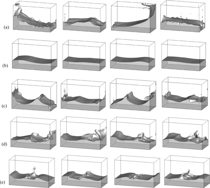
Fig: Sloshing phenomenon in tank
Under low gravity field, the surface tension is dominant and the liquid may be oriented randomly within the tank depending essentially upon the wetting characteristics of the tank wall. The basic problem of liquid sloshing involves the estimation of hydrodynamic pressure distribution, forces, moments and natural frequencies of the free-liquid surface. These parameters have a direct effect on the dynamic stability and performance of moving containers. Liquid sloshing strongly influences the directional dynamics and safety performance of tank vehicles. Anti-slosh devices such as baffles are widely used in order to limit the adverse liquid slosh effect on directional performance and stability of vehicle.
Generally, the hydrodynamic pressure of liquids in moving rigid containers has two distinct components. One component is directly proportional to the acceleration of the tank. This component is caused by the part of the fluid moving with the same tank velocity. The second is known as “convective” pressure and represents the free-surface-liquid motion. Mechanical models such as mass-spring-dashpot or pendulum systems are usually used to model the sloshing part.
Dynamic meshing:-
The dynamic mesh model can be used to model flows where the shape of the domain is changing with time due to motion on the domain boundaries. In ANSYS Fluent the dynamic mesh capability is used to simulate problems with boundary motion.
The building blocks for dynamic mesh capabilities within ANSYS Fluent are three dynamic mesh schemes, namely, smoothing, layering, and remeshing. A combination of these three schemes is used to tackle the most challenging dynamic mesh problems. However, for simple dynamic mesh problems involving linear boundary motion, the layering scheme is often sufficient.
The schemes are as follows-
- Smoothing:- The smoothing method adjusts the mesh of an area by moving or deforming boundaries, but the number of nodes and connections does not change.
- Layering:- The dynamic layering method is used when multilayers of cells are added to or subtracted from the cell layer adjacent to the moving boundary. This can be based on the layer height adjacent to the moving surface, meaning that the cell layer adjacent to the moving border is subdivided or merged with its subsequent cell layer, and in fact requires an ideal height limit.
- Remeshing:- The remeshing method is used for situations where the boundary displacement is large compared to the size of the local cells, which causes the cell quality to deteriorate; thus, the mesh becomes invalid.
Applications of dynamic meshing:-
- Check valves
- Train movement in tunnel with varying velocity
- Flap movement of airplane wing
- Combustion in ICE
- Blood flow pumping through human heart
User defined function (UDF):-
A user-defined function, or UDF, is a function that we program and can be dynamically loaded with the ansys fluent solver to enhance the standard features of the code. UDFs are written in the C programming language. UDFs are written in C using any text editor and the source file is saved with a .c file extension. Source files typically contain a single UDF, but they can contain multiple concatenated functions.
Every UDF contains the udf.h file inclusion directive (#include "udf.h") at the beginning of the source code file, which allows definitions for DEFINE macros and other Fluent-provided macros and functions to be included during the compilation process. For compiled UDFs, the process involves two separate steps. A shared object code library is first built and then it is loaded into fluent solver. Once interpreted or compiled, UDFs will become visible and selectable in fluent graphics panels, and can be hooked to a solver by choosing the function name in the appropriate panel.
UDFs are executed as either interpreted or compiled functions in FLUENT. Values that are passed to the solver by a UDF or returned by the solver to a UDF must be specified in SI units.
UDF allows user to perform following functions-
- Return a value
- Modify an argument
- Write / read information in case or data file
- Enhance existing fluent models (e.g., discrete phase model, multiphase mixture model, discrete ordinates radiation model)
- Customize boundary condition, material property definitions, source terms, etc.
Pre-processing:-
Geometry preparation:-
Steps for geometry preparations are as follows-
- Importing 3D model
- Selecting required edges for volume extraction
- Extracting fluid volume from 3D model
- Splitting fluid volume from center to obtained 2D surface
- Prepare 2D surface
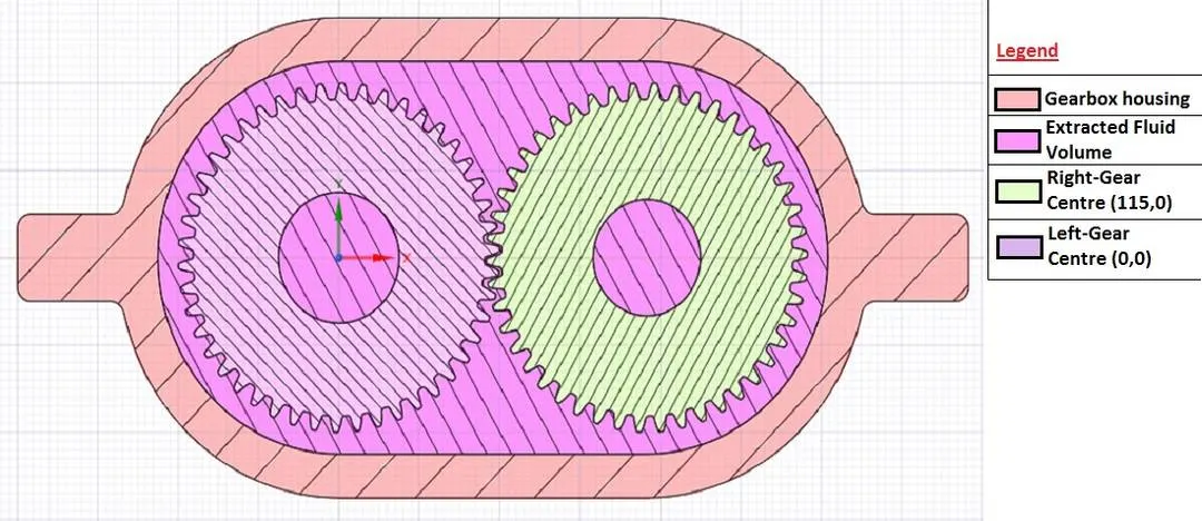
Fig: Section view of Gear-box
We have imported STEP model file of gearbox in ANSYS Space-Claim. Then By selecting edges we have extracted fluid volume through gearbox using volume extraction command in Space-Claim. The above picture clarifies prepared geometry for performing simulation.
Due to student version license restriction, high computational memory and time we have copied extracted volume face into another geometry and instead of 3D we are conducting 2D simulation.
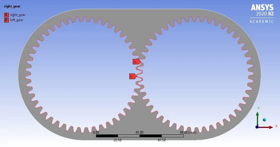
Fig: 2D Geometry
Above figure shows 2D geometry for simulation.
Label "A" denotes Right gear and label "B" denotes left gear. We need to select individually edges of gears using edge selector and then using named selection we have to give names to it.
Meshing:-
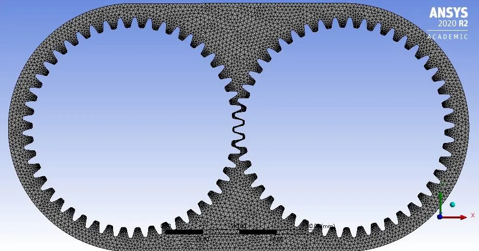
Fig: Meshed geometry
Above figure shows meshed geometry. The meshing method is provided for uniform and fine meshing. Triangular mesh is provided for elements. By enabling proximity and giving number of cells across gap 2, we get fine mesh elements. Also we have provided elements size of 2mm. Hence we get-
Number of nodes = 6848,
Number of elements = 11343.
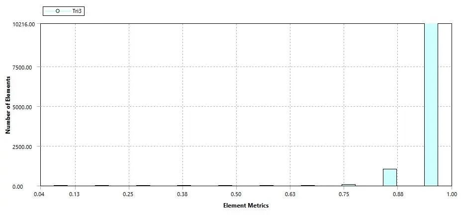
Fig: Mesh element quality matrix
As per above defined mesh settings we get mesh quality matrix which is shown in above figure.
Materials:-
Following lubricating fluid materials are used in simulation.
1. Engine oil
Density = 889 kg/m^3
Viscosity = 1.06 kg/m-s
2. n-heptane `(C_7H_16)`
Density = 684 kg/m^3
Viscosity = 0.000409 kg/m-s
Solving:-
UDF code:-
#include "udf.h"

DEFINE_CG_MOTION(right_motion, dt, vel, omega, time, dtime)
{
	vel[0] = 0.0;
	vel[1] = 0.0;
	vel[2] = 0.0;

	omega[0] = 0.0;
	omega[1] = 0.0;
	omega[2] = 2.0e2; /* [rad/s]*/
}
DEFINE_CG_MOTION(left_motion, dt, vel, omega, time, dtime)
{
	vel[0] = 0.0;
	vel[1] = 0.0;
	vel[2] = 0.0;

	omega[0] = 0.0;
	omega[1] = 0.0;
	omega[2] = -2.0e2; /* [rad/s]*/
}
Above code is a user defined function, which defines rotational velocity with 200 rad/sec.
As per above user defined function,
Rotational velocity, `omega = 200 (rad)/sec`
As we know,
`omega=(2piN)/60`
`:. N=(omegaxx60)/(2pi)`
`:. N=(200xx60)/(2pi)=6000/pi`
`:.N=1909.8593` RPM
`:.N=31.831 RPS`
Hence time required for gear to complete single rotation,
`1/N=1/31.831=0.03141`
Thus time = 0.03141 Seconds.
For simulation consider at least 2 revolution of gear to observe good results.
So minimum time required to perform simulation is `0.03141xx2=0.06283` Seconds.
Solver settings: The solver settings are as follows-
- Pressure based solver
- Transient solver
- Enable gravity of 9.81 in -ve Y direction
- Enable multiphase model
- Enable volume of fluid option with two phases
- Choose implicit scheme to minimize errors due to CFL conditions
- For viscous turbulent model choose K-epsilon model
- Enable enhanced wall function option
After this solver setting create dynamic mesh using appropriate values, for avoiding errors maximum skewness is set to 0.7.
Then UDF is added using add option in UDF tab. After it by using build command and load command UDF is loaded in case setup.
Then left rotating motion (clock-wise rotation) is given to left gear and right motion (anticlock-wise) is given to right gear through creating dynamic mesh zones.
After all these steps initialize solution and then patch regions.
~Case 1:- 20% immersion off lubricant
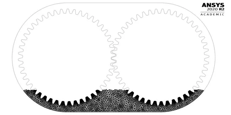
Fig: 20% immersion of lubricant fluid
The above figure shows gearbox geometry where shaded region denotes lubrication fluid region.
As we know height of gearbox is 135mm. So for 20% immersion-
This region is defined using Adapt / Mark option. For defining this region we need to defined diagonal elements of region.
`0.2xx135=27mm`
So to obtained co ordinates draw a line parallel to X-axis at 27mm above base.
| X coordinate | Y coordinate | ||
| Max | Min | Max | Min |
| -0.054 | 0.169 | -0.041 | -0.068 |
Above table shows coordinates for defining fluid region.
~Case 1.1:- Engine oil as lubricant
Number of timesteps = 650
Timestep size = 0.0001 second
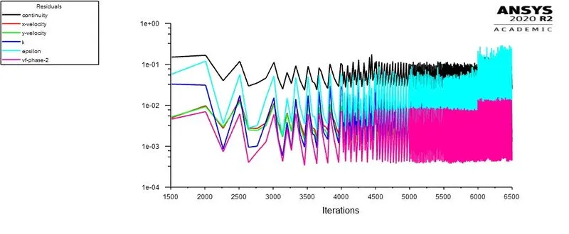 Fig: Residual plot
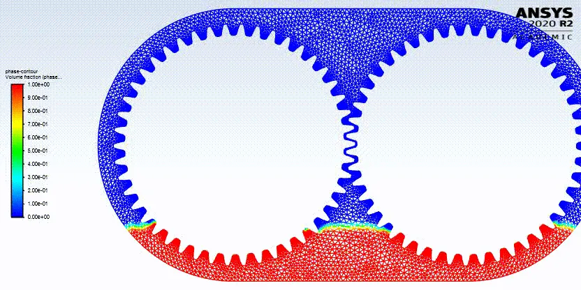 Fig: 20% immersion of engine oil
~Case 1.2:- n-Heptane as lubricant
Number of timesteps = 650
Timestep size = 0.0001 second
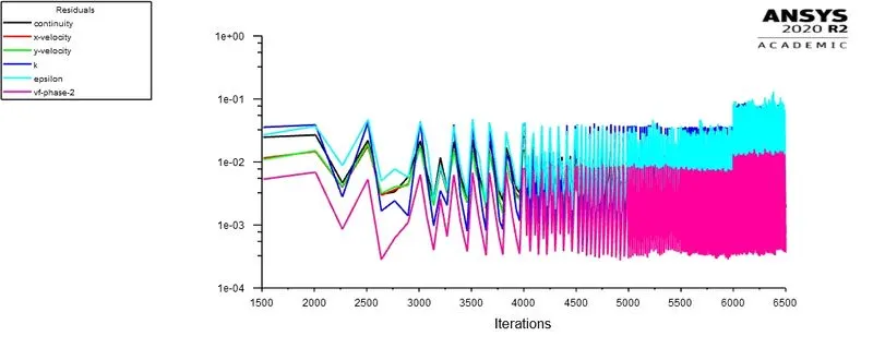 Fig: Residual plot
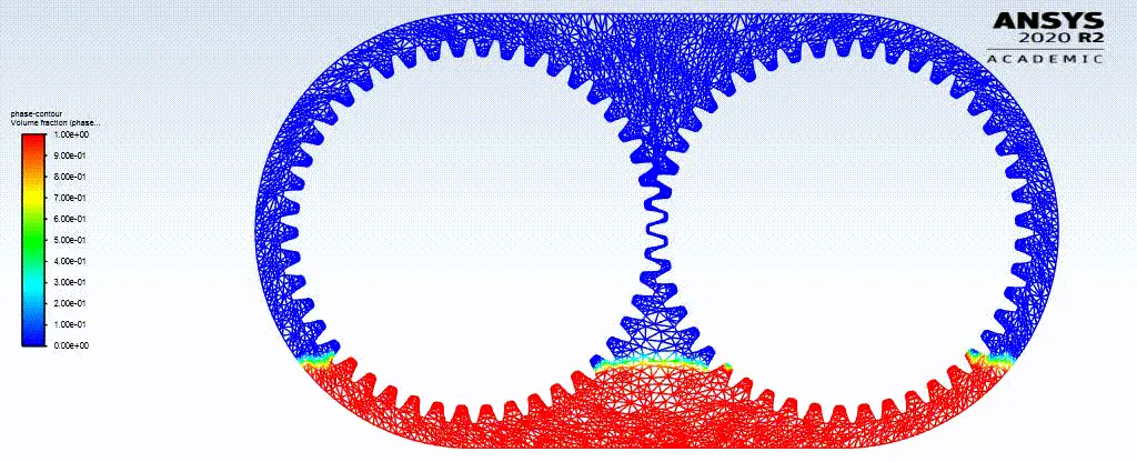
Fig: 20% immersion of n-heptane
~Case 2:- 30% immersion off lubricant
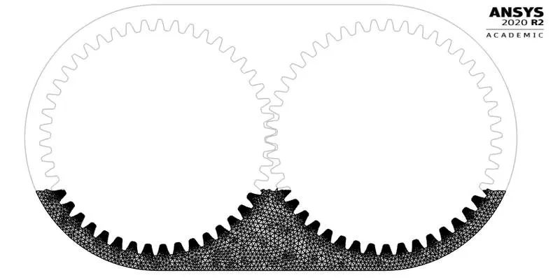
Fig: 30% immersion of lubricant fluid
The above figure shows gearbox geometry where shaded region denotes lubrication fluid region.
As we know height of gearbox is 135mm. So for 30% immersion-
This region is defined using Adapt / Mark option. For defining this region we need to defined diagonal elements of region.
`0.3xx135=40.5mm`
So to obtained co ordinates draw a line parallel to X-axis at 40.5mm above base.
| X coordinate | Y coordinate | ||
| Max | Min | Max | Min |
| -0.062 | 0.177 | -0.0275 | -0.068 |
Above table shows coordinates for defining fluid region.
~Case 2.1:- Engine oil as lubricant
Number of timesteps = 1000
Timestep size = 0.0001 second
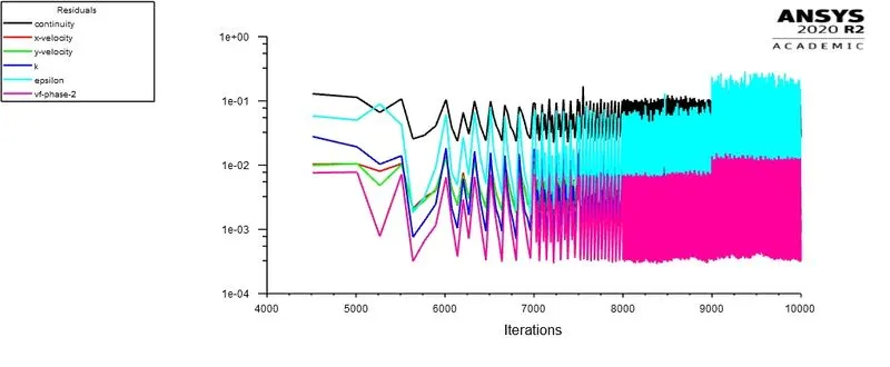
Fig: Residual plot
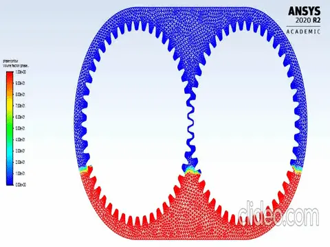
Fig: 30% immersion of engine oil
~Case 2.2:- n-Heptane as lubricant
Number of timesteps = 650
Timestep size = 0.0001 second
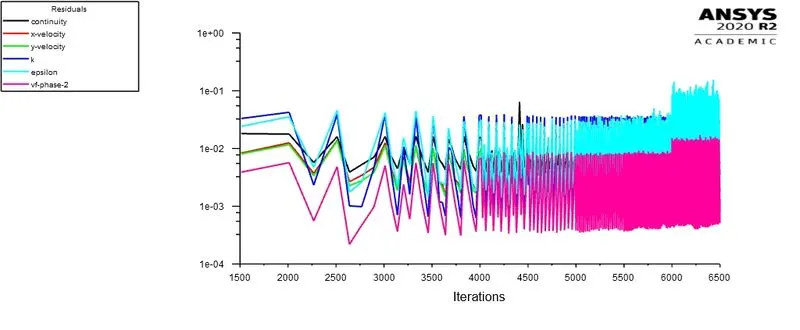
Fig: Residual plot
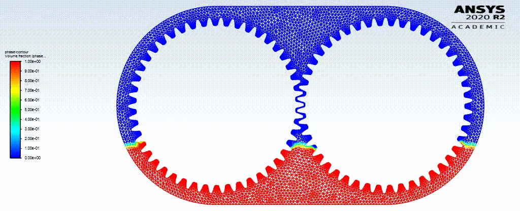
Fig: 30% immersion of n-heptane
Errors found during simulation:
While performing above simulation one may face errors like dynamic mesh failed, negative cell volume detected or floating point errors, so for getting quality result we need to overcome those errors.
a. Dynamic mesh failed:
This error may arises many times due to improper selection of required edges. In this case this error arises due to improper selection of gear edges. Also improper settings of smoothing, layering and remeshing can increase such errors.
To avoid this error we can-
- Try to increase mesh quality
- Try to select required edges carefully
- Manipulate mesh scale in dynamic mesh
b. Negative cell volume detected:
The negative cell volume error is shown when the mesh has been updated in a way to cause a negative cell volume (non-physical).
Possible factors for causing this error include:
- Overlapping nodes
- Significant mesh motion (relative to cell size) per step.
To avoid this error we can-
- Try to reduce the time step
- Try to reduce mesh size
- Try to provide skewness of 0.7
- Try to provide appropriate remeshing inputs
c. Floating point error:
This error arises when solver detects an error which is unable to compute or having mathematical error in calculation. For example divided by zero or a value which is very closed to zero.
To avoid this errors we can-
- Try to reduce mesh size
- Try to reduce time step
- By applying under relaxation
Conclusion:-
By observing above animation files, data and results we can conclude that-
- Lubrication is necessary in case of gearbox to reduce wear and tear of gear teeth.
- Sloshing effect is more in case of n-Heptane as compared to engine oil.
- As engine oil posses more viscosity than n-Heptane it will result more stickiness and less wear of gear teeth.
- 30% immersion is more effective than 20% immersion. as it will provide perfect lubrication to all gear teeth.
- To perform dynamic mesh, appropriate and correct setting values are needed to avoid errors.
- By considering above cases engine oil with 30% immersion is preferable for design.