Modelling of SI and CI engine with after-treatment device using GT Power
Aim:-> Aftertreatment devices modelling for CI and SI Engines using GT Power.
Theory:
An aftertreatment system is a method or device for reducing harmful exhaust emissions from internal-combustion engines. In other words, it is a device that cleans exhaust gases to ensure the engines meet emission norms which are imposed by government. To obtained clean exhaust gases after combustion complex exhaust or emission aftertreatment systems are added. These systems treat post-combustion gases after they leave the engine, reducing environmental impact without sacrificing power or performance. A properly maintained aftertreatment system ensures that emissions are kept at or below government regulation requirements.
Emission standards are the legal requirements governing air pollutants released into the atmosphere. Emission standards set quantitative limits on the permissible amount of specific air pollutants that may be released from specific sources over specific timeframes. They are generally designed to achieve air quality standards and to protect human life. Different regions and countries have different standards for vehicle emissions.
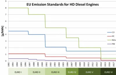 |
The above figure shows emission norms provided by European government as per European standard. In India we have similar emission norms provided by Indian government under name of Bharat Stage (BS). An emission performance standard is a limit that sets thresholds above which a different type of vehicle emissions control technology might be needed. While emission performance standards have been used to dictate limits for conventional pollutants such as oxides of nitrogen and oxides of Sulphur (NOx and SOx), this regulatory technique may be used to regulate greenhouse gasses, particularly carbon dioxide (CO2).
Until the middle of the 20th century the number of IC engines in the world was so small that the pollutions, they caused was tolerable. During that period the environment, with the help of sunlight, stayed relatively clean. As world population grew, power plants, factories, and an ever-increasing number of automobiles began to pollute the air to the extent that it was no longer acceptable. It becomes very necessary as emission due to vehicle are very hazardous and making very bad impact on nature. Motor vehicle emissions contribute to air pollution and are a major ingredient in the creation of smog (smoke + fog) in some large cities. Emissions of many air pollutants have been shown to have variety of adverse effects on public health like leading in skin cancer and the natural environment like global warming.
~Types of emissions:
- NOx (Oxides of Nitrogen) : Exhaust gases of an engine can have up to 2000 ppm of oxides of nitrogen. Most of this will be nitrogen oxide (NO), with a small amount of nitrogen dioxide (NO2). There will also be traces of other nitrogen-oxygen combinations. These are all grouped together NOx, with x representing some suitable number. NOx is very undesirable. At low temperatures, atmospheric nitrogen exists as a stable diatomic molecule due to energy limitations. Therefore, only very small trace amounts of oxides of nitrogen are found. However, at very high temperatures that occur in the combustion chamber of an engine, some diatomic nitrogen (N2) breaks down to monatomic nitrogen (N) which are reactive as it goes endothermic reaction producing various oxides of Nitrogen. Generation of NOx (NO & NO2) can be shown by following reactions:
`O+N_2->NO+N`
`N+O_2->NO+O`
`NO+O_2->NO_2+O`
In addition to temperature, the formation of NOx depends on pressure and air-fuel ratio. Combustion duration plays a significant role in NOx formation within the cylinder.
- SOx (Oxides of Sulfur) : A general term for oxides of sulfur, which are emitted from motor vehicles burning fuel containing sulfur. Reducing the level of fuel sulfur reduces the level of Sulfur oxide emitted from the tailpipe. Sulfur dioxide (SO2) is a colorless, reactive gas with a strong odor. Sulfur dioxide comes from a variety of natural and anthropogenic sources. The following reaction can show the generation of Sulphur oxides
`H_2+S->H_2S`
`O_2+S->SO_2`
`2SO_2+O_2->2SO_3`
Many fuels used in CI engines contain small amounts of Sulphur. When exhausted in the form of SO2 and SO3 (called SOx) they contribute to the acid rain problem of the world. Unleaded gasoline generally contains 150-550 ppm Sulphur by weight. Some diesel fuels contain up to 5500 ppm by weight, but in the developed countries this is restricted by law to a tenth of this value or less.
- PM (Particulate matter) : The exhaust of CI engines contains solid carbon soot particles that are generated in the fuel-rich zones within the cylinder during combustion. These are seen as exhaust smoke and cause an undesirable odorous pollution. Maximum density of particulate emissions occurs when the engine is under load. At this condition maximum fuel is injected to supply maximum power, resulting in a rich mixture and poor fuel economy. This can be seen in the heavy exhaust smoke emitted when a truck or railroad locomotive accelerates up a hill or from a stop. Soot particles are clusters of solid carbon spheres. These spheres have diameters from 9 nm to 90 nm. But most of them are within the range of 15-30 nm. The spheres are solid carbon with HC and traces of other components absorbed on the surface. A single soot particle may contain up to 5000 carbon spheres.
Up to about 25% of the carbon in soot comes from lubricating oil components which vaporize and then react during combustion. The rest comes from the fuel and amounts to 0.2-0.5% of the fuel. Because of the high compression ratios of CI engines, a large expansion occurs during the power stroke. This makes the gases within the cylinder cooled to a relatively low temperature. This causes the remaining high-boiling-point components found in the fuel and lubricating oil to condense on the surface of the carbon soot particles. This absorbed portion of the soot particles is called the soluble organic fraction (SOF), and the amount is highly dependent on cylinder temperature. Particulate matter causes negative health effects, including but not limited to respiratory disease and cancer. Very fine particulate matter has been linked to cardiovascular disease.
- HC (Unburnt hydro carbons) : A class of burned or partially burned fuel, hydrocarbons are toxins. When hydrocarbon emissions get into the atmosphere, they act as irritants and odorants; some are carcinogenic. All components except CH4 react with atmospheric gases to form photochemical smog hence Hydrocarbons are a major contributor to smog, which can be a major problem in urban areas. Prolonged exposure to hydrocarbons contributes to asthma, liver disease, lung disease, and cancer. Regulations governing hydrocarbons vary according to type of engine and jurisdiction; in some cases, "non-methane hydrocarbons" are regulated, while in other cases, "total hydrocarbons" are regulated. Hydrocarbon emissions will be different for each gasoline blend, depending on the original fuel components. Combustion chamber geometry and engine operating parameters also influence the HC component spectrum.
- CO (Carbon monoxide) : Carbon monoxide is a colorless and odorless but a poisonous gas. It is generated in an engine when it is operated with a fuel-rich equivalence ratio. When there is not enough oxygen to convert all carbon to CO2, some fuel does not get burned and some carbon ends up as CO. Rich mixture is required during starting or when accelerating under load. Even when the intake air-fuel mixture is stoichiometric or lean, some CO will be generated in the engine. Not only is CO considered an undesirable emission, but it also represents lost chemical energy. CO is a fuel that can be combusted to supply additional thermal energy:
`CO+1/2O_2->CO_2+Heat`
By inhaling carbon monoxide reduces the blood's ability to carry oxygen; overexposure (carbon monoxide poisoning) may be fatal. (Carbon monoxide persistently binds to hemoglobin, the oxygen-carrying chemical in red blood cells, where oxygen (O2) would temporarily bind.
Particulate generation can be reduced by engine design and control of operating conditions, but quite often this will create other adverse results. If the combustion time is extended by combustion chamber design and timing control, particulate amounts in the exhaust can be reduced. Soot particles originally generated will have a greater time to be mixed with oxygen and combusted to CO2. However, a longer combustion time means a high cylinder temperature and more NOx generation. Dilution with EGR lowers NOx emissions but increases particulates and HC emissions. Higher injection pressure gives a finer droplet size. This will reduce HC and particulate emissions but increases cylinder temperature and NOx emissions. Engine management systems are programmed to minimize CO, HC, NOx, and particulate emissions by controlling ignition timing, injection pressure, injection timing, and/or valve timing. Obviously, some sort of compromise is much necessary.
~Aftertreatment devices:
1. EGR (Exhaust gas recirculation):
The most effective way of reducing NOx emissions is to hold combustion chamber temperatures down. Although practical, this is a very unfortunate method in that it also reduces the thermal efficiency of the engine. As we aware that to obtain maximum engine thermal efficiency it should be operated at the highest temperature possible. The simplest and practical method of reducing maximum flame temperature is to dilute the air-fuel mixture with a nonreacting parasite gas. This gas absorbs energy during combustion without contributing any energy input. The net result is a lower flame temperature. The gases with larger specific heats would absorb the most energy per unit mass and would therefore require the least amount; thus, less CO2 would be required than argon for the same maximum temperature. However, neither CO2 nor argon is readily available for use in an engine. Air is available as a diluent but is not totally nonreacting. Adding air changes the air-fuel ratio and combustion characteristics. The one nonreacting gas that is available to use in an engine is exhaust gas, and this is used in all modern automobile and other medium-size and large engines.
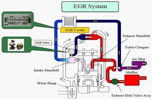 |
Exhaust gas recycle (EGR) is done by ducting some of the exhaust flow back into the intake system, usually immediately after the throttle. The amount of flow can be as high as 30% of the total intake. EGR combines with the exhaust residual left in the cylinder from the previous cycle to effectively reduce the maximum combustion temperature. Not only EGR reduce the maximum temperature in the combustion chamber, but it also lowers the overall combustion efficiency. So, increase in EGR results in some cycle partial burns and, in the extreme, total misfires. Thus, by using EGR to reduce NOx emissions, a costly price of increased HC emissions and lower thermal efficiency must be paid. A problem unique to CI engines when using EGR is the solid carbon soot in the exhaust. The soot acts as an abrasive and breaks down the lubricant. Greater wear on the piston rings and valve train results.
2. Catalytic converter: The most effective aftertreatment for reducing engine emissions is the catalytic converter found on most automobiles and other modern engines of medium or large size. Generally, catalytic converters are called three-way converters because they are used to reduce the concentration of CO, HC, and NOx in the exhaust. Catalytic converter is usually a stainless-steel container mounted somewhere along the exhaust pipe of the engine. Inside the container is a porous ceramic structure through which the exhaust gas flows. In most converters, the ceramic is a single honeycomb structure with many flow passages. Some converters use loose granular ceramic with the gas passing between the packed spheres. Volume of the ceramic structure of a converter is generally about half the displacement volume of the engine. This results in a volumetric flow rate of exhaust gas such that there are 5 to 30 changeovers of gas each second, through the converter. Catalytic converters for CI engines need larger flow passages because of the solid soot in the exhaust gases.
A catalyst is a substance that accelerates a chemical reaction by lowering the energy needed for it to proceed. The catalyst is not consumed in the reaction and so functions indefinitely unless degraded by heat, age, contaminants, or other factors. Catalytic converters are chambers mounted in the flow system through which the exhaust gases pass through. These chambers contain catalytic material, which promotes the oxidation of the emissions contained in the exhaust flow. In gasoline catalytic converter application, the active catalytic materials are present as a thin coating of precious metal which is also known as catalyst metal and oxide-based inorganic promoters and support materials on the internal walls of the honeycomb substrate. The substrate typically provides a large number of parallel flow channels to allow for sufficient contacting area between the exhaust gas and the active catalytic materials without creating excess pressure losses. The catalyst materials most commonly used are platinum, palladium, and rhodium. Palladium and platinum promote the oxidation of CO and HC, with platinum especially active in the hydrocarbon reaction. Rhodium promotes the reaction of NOx in one or more reactions.
-Two way catalytic converter-
Oxidation of carbon monoxide to carbon dioxide
`2.CO+O_2->2.CO_2`
Oxidation of hydrocarbon to carbon dioxide and water
`C_xH_(2(x+1)) + ((3x+1)/2).O_2 → x.CO_2 + (x+1).H_2O`
-Three way catalytic converter-
Reduction of nitrogen oxides to nitrogen and oxygen
`2.NO_x → x.O_2 +N_2`
Oxidation of carbon monoxide to carbon dioxide
`2.CO+O_2->2.CO_2`
Oxidation of hydrocarbon to carbon dioxide and water
`C_xH_(2(x+1)) + ((3x+1)/2).O_2 → x.CO_2 + (x+1).H_2O`
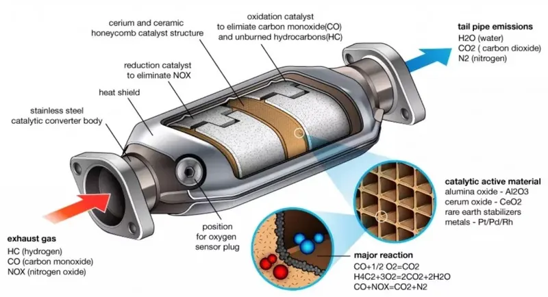 |
It is important that a catalytic converter be operated hot to be efficient, but not hotter. Engine malfunctions can cause poor efficiency and overheating of converters. A poorly tuned engine can have misfires and periods of too lean and/or too rich conditions. These cause the converter to be inefficient. A turbocharger lowers the exhaust temperature by removing energy, and this can make a catalytic converter less efficient. It is desirable that catalytic converters have an effective life time equal to that of the automobile or at least 200,000 km. Converters lose their efficiency with age due to thermal degradation and poisoning of the active catalyst material. At high temperature the metal catalyst material can sinter and migrate together. This can cause larger active sites which are, overall, less efficient. Serious thermal degradation occurs in the temperature range of 500–900 degree C. A number of different impurities contained in fuel, lubricating oil, and air find their way into the engine exhaust and poison the catalyst material.
3. Diesel oxidation catalyst (DOC): A diesel oxidation catalyst consists of a stainless steel canister that contains a honeycomb structure called a substrate or catalyst support. There are no moving parts, just large amounts of interior surface area. The interior surfaces are coated with precious metals such as platinum or palladium as oxidation catalytic material. It is called an oxidation catalyst because the device converts exhaust gas pollutants into harmless gases by means of chemical oxidation. the catalyst oxidizes CO, HC, and the liquid hydrocarbons adsorbed on carbon particles. Catalyst metals promote the removal of 30–80% of the gaseous HC and 40–90% of the CO in the exhaust. The catalysts have little effect on solid carbon soot but do remove 30–60% of the total particulate mass by oxidizing a large percent of the HC absorbed on the carbon particles. Diesel oxidation catalysts are efficient at converting the soluble organic fraction of diesel particulate matter into carbon dioxide and water. But for CI engines DOC is not efficient at reducing NOx due to their overall lean operation. HC and CO can be adequately reduced, although there is greater difficulty because of the cooler exhaust gases of a CI engine (due to the larger expansion ratio). NOx is reduced in a CI engine by the use of SCR.
4. Diesel particulate filter (DPF): Compression ignition engine systems are equipped with particulate traps called as Diesel particulate filters in their exhaust flow to reduce the amount of particulates released to the atmosphere by filtering exhaust gases from the engine. This is performed in order to meet the stringent particulate emissions that are required for diesel light duty vehicles. The basis for the design of wall flow filters is a honeycomb structure with alternate channels plugged at opposite ends. As the gasses passes into the open end of a channel, the plug at the opposite end forces the gasses through the porous wall of the honeycomb channel and out through the neighboring channel. The ultrafine porous structure of the channel walls results in greater than 90% percent collection efficiencies of these filters. Wall flow filters capture particulate matter by interception and impaction of the solid particles across the porous wall. The exhaust gas is allowed to pass through in order to maintain low pressure drop.
As traps catch the soot particles, they slowly fill up with the particulates. This restricts exhaust gas flow and raises the back pressure of the engine. Higher back pressure causes the engine to run hotter, the exhaust temperature to rise, and fuel consumption to increase. To reduce this flow restriction, particulate traps are regenerated when they begin to saturate. Regeneration consists of combusting the particulates in the excess oxygen contained in the exhaust of the lean-operating CI engine. Modern particulate traps are not totally satisfactory, especially for automobiles. They are costly and complex when equipped for regeneration, and long-term durability does not exist. An ideal catalytic trap would be simple, economical, and reliable; it would be self-regenerating; and it would impose a minimum increase in fuel consumption.
5. Selective catalytic converter (SCR): The Selective Catalytic Reduction (SCR) - an emissions reduction technology with the ability to deliver near-zero emissions of Nitrogen Oxides (NOx), a smog causing pollutant and greenhouse gas. This technology requires treating the exhaust stream with a spray of diesel exhaust fluid (DEF) - an ammonia-based solution. DEF. DEF is a solution of purified water and urea, an organic nitrogen compound that turns to ammonia when heated. When DEF is injected into the exhaust pipe downstream of the engine, the heat of the engine exhaust gases decomposes DEF into ammonia and CO2. Vaporized DEF and hot exhaust gases enter a catalytic converter located in the exhaust system after the DPF (diesel particulate filter). When the NOx reacts inside the catalyst with the ammonia, the harmful NOx molecules in the exhaust are converted to harmless nitrogen and water, which are clean, harmless and present in the air we breathe every day. Three forms of DEF can be used in SCR systems: pure anhydrous ammonia, aqueous ammonia and urea.
- Ammonia SCR system:
In this SCR process, NOx reacts with the ammonia, which is injected into the exhaust gas stream before a special SCR Catalyst.
`4.NO + 4.NH_3 + O_2 -> 4.N_2 + 6.H_2O`
An ammonia SCR control system is an open loop configuration, where a pre-programmed map of engine NOx emissions is used to control the ammonia injection rate. This open loop configuration is capable of some 95% NOx reductions. The automotive industry recognizes that it offers the most effective SCR solution for mobile applications. Ammonia injection systems are not practical in automobiles or on other smaller engines. This is because of the needed NH3 storage and fairly complex injection and control system.
- Urea SCR system:
In this SCR process, NOx reacts with urea, which is injected into the exhaust gas stream before a SCR catalyst.
`CO(NH_2)_2 + H_2-> 2.NH_3 + CO_2`
In case of urea SCR system, urea cannot be directly injected in system like ammonia. Urea needs heat to decompose it into ammonia first and then it will react with exhaust.
SI Engine + Aftertreatment modelling:
~Model description:
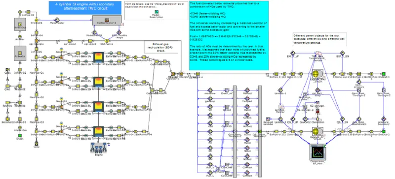
This example demonstrates modeling an SI engine combined with a detailed Three Way catalytic converter (TWC) in a secondary aftertreatment circuit. The original base model SI_4cyl_EGRController was combined with the aftertreatment example model TWC_Ramanathan_and_Sharma, which uses a published reaction mechanism for a passenger car TWC. A secondary circuit is used to solve the reactions using the quasi-steady (QS) flow solver, which is able to use a large master time step so that it does not restrict the computation time. The back pressure from the explicit engine circuit is passed to the QS circuit and actuated as the downstream pressure boundary, and the outlet gas temperature from the QS circuit is passed back to the explicit engine circuit and actuated as the TWC wall temperature so that the exothermic heat release is captured for acoustics. A resonator and muffler could then be added downstream of the TWC. The various monitors show the TWC conversion efficiency, the exhaust lambda, the oxygen storage, the temperature upstream and downstream of the TWC, and the deltaT across the TWC.
~Circuit model:
~Engine cylinder:
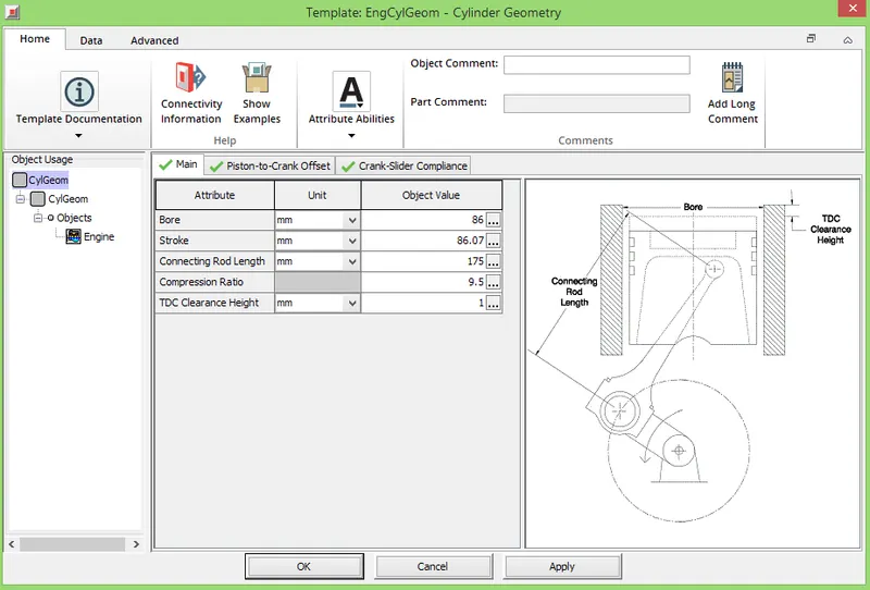
~Combustion modelling:
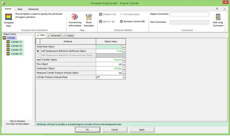
~Pollutant modelling:
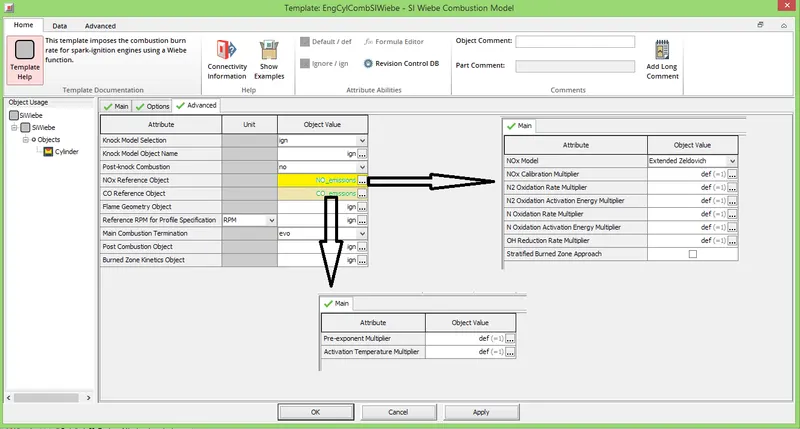
~3 Way Catalytic converter:
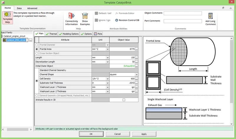
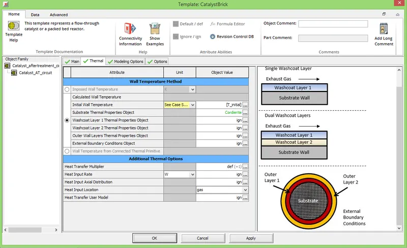
~3 Way Catalytic converter thermal:
~Case setup:
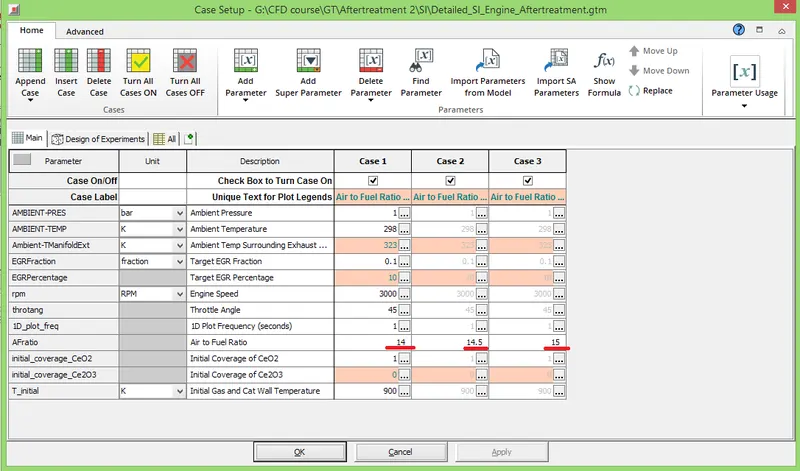
In this case setup air-fuel ration is kept as variable parameter and other parameters are kept unchanged. It is created in order to check its effect on exhaust gases and amount of pollutants at tailpipe.
~Performance parameters:
~Key cylinder properties:
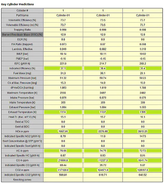
The above figure shows properties of 1st cylinder in each case only.
~Comments on achieved results:
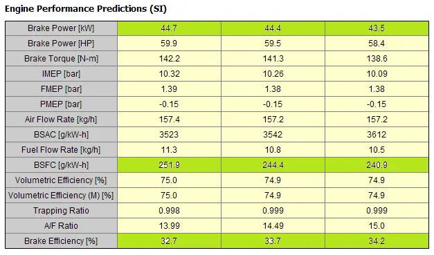
From the above result it is seen that indicated efficiency is increasing with increase in Air Fuel ratio. As we know increase in air fuel ratio means increasing concentration of air in a charge, which means increase in oxygen i.e., better burning which increases efficiency. As burning is better which raises temperature of exhaust gases and due to high temperature NOx also get increased. And due to better combustion most of the fuel particles get utilized to generate more CO2 and pollutants like HC and CO reduces. Due to better burning, brake power is also getting improved with BSFC (Break specific fuel consumption).
CI Engine + Aftertreatment modelling:
~Model description:
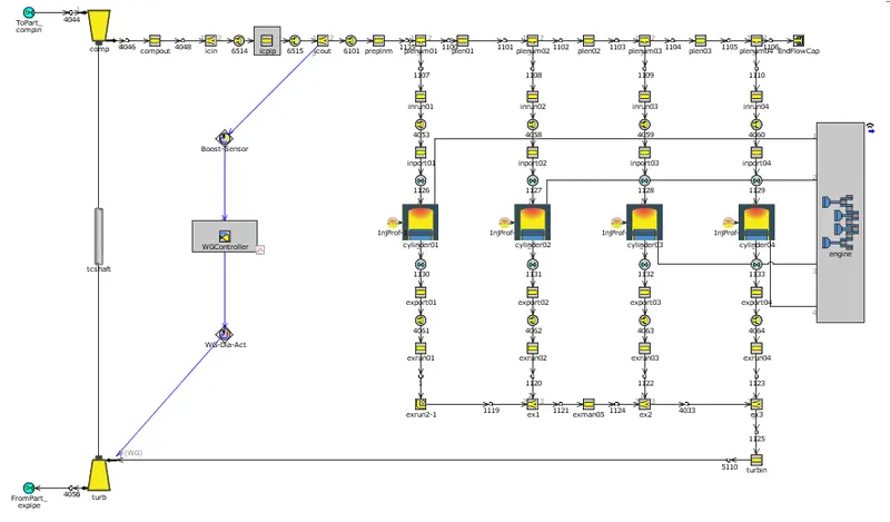
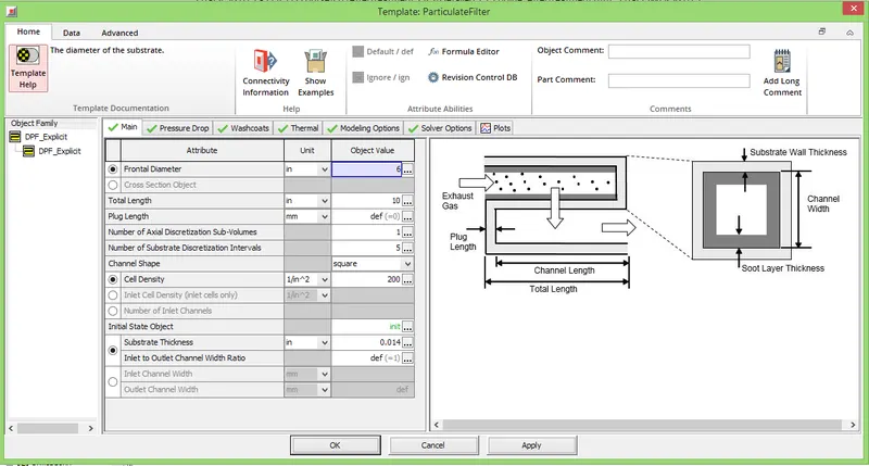
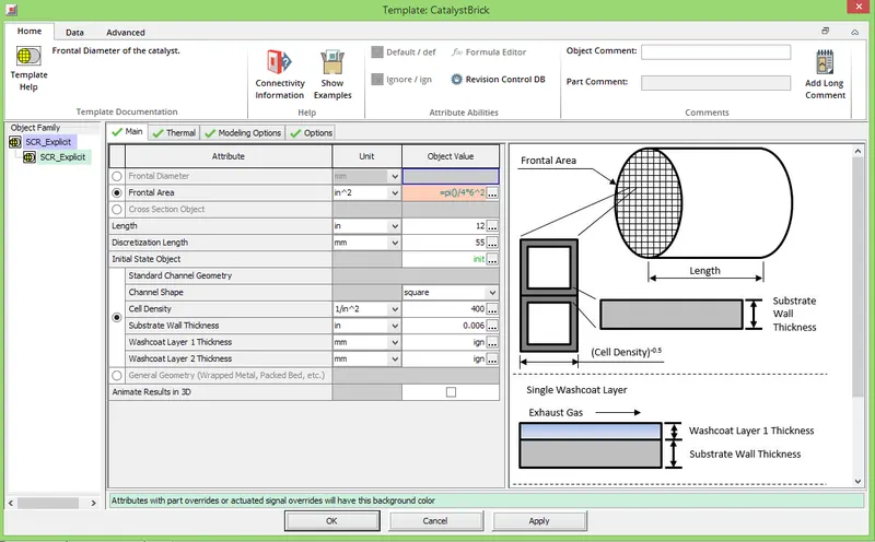
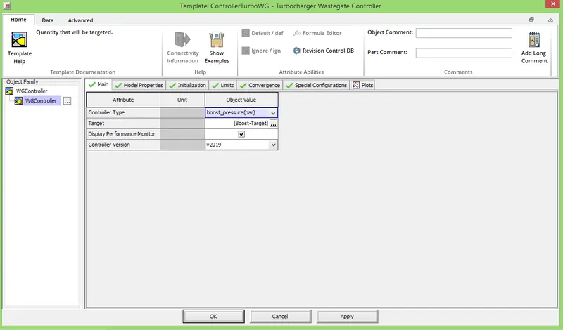
This example demonstrates an integrated model with detailed engine and detailed aftertreatment system running one steady-state operating point. The detailed engine model comes from the Diesel_WGController example in the Engine Performance directory. The detailed aftertreatment system is a combination of the DOC_Sampara_and_Bissett and SCR_Fe_Zeolite example models along with a DPF setup for passive regeneration only, and same urea injection system used in the EngineState_Vehicle_Aftertreatment_NEDC example model. The model is set to shut-off at steady-state and has several Convergence RLTs set under Run Setup > ConvergenceRLT to establish convergence. The global wall temperature solver is set to "transient" because the QS Advanced Adaptive solver used in the DOC and SCR catalysts requires it. The exhaust system is duplicated such that one copy uses the explicit flow solver and the second copy uses the quasi-steady (QS) flow solver with larger, 0.1 second time step. The explicit and QS flow circuit settings are controlled under Home > Run Setup > FlowControl. The explicit solver time step is automatically controlled, but the QS circuit time step is user-imposed. Notice that when the "Improved Solution Sequence for Multi-Circuit Models" is activated in Run Setup > TimeControl, the QS circuit can use a "continuous" flag in Run Setup > FlowControl. A QS time step of 0.1 seconds or less is recommended.
~Circuit model:
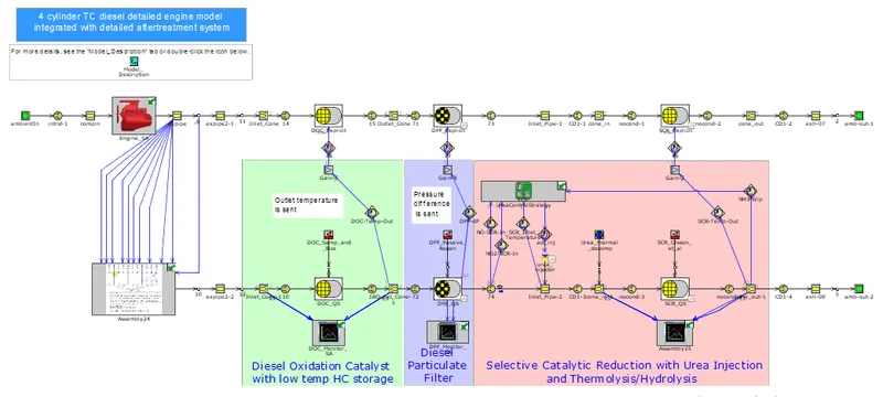
~Assembly circuit:
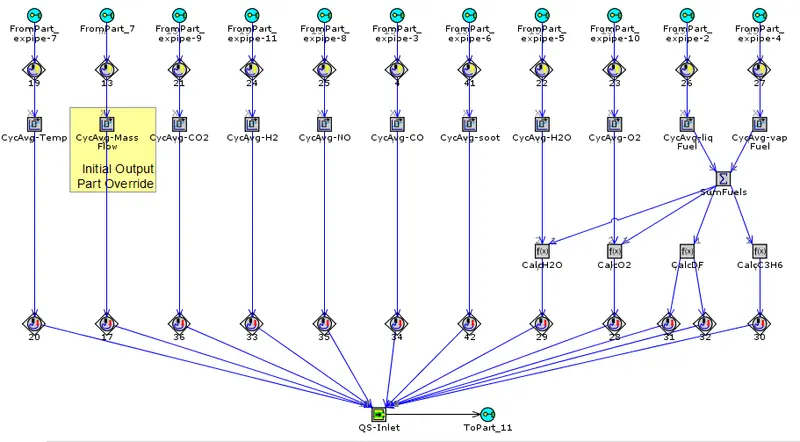
~Engine circuit model:
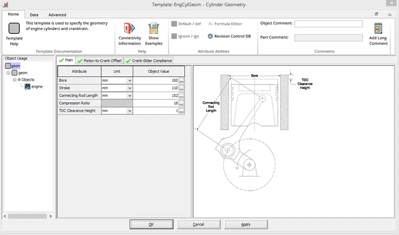
~Engine cylinder:
~Combustion DIWiebe:
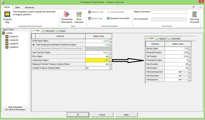
~NOx modelling:
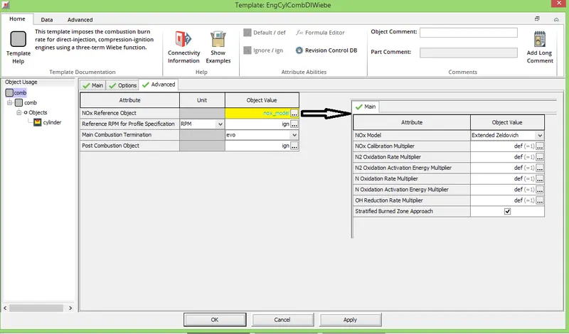
~Soot modelling:
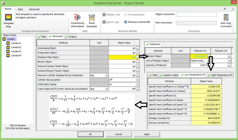
~DOC:
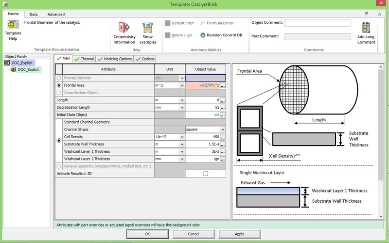
~DPF:
~SCR:
~Wastegate controller:
~Case setup:
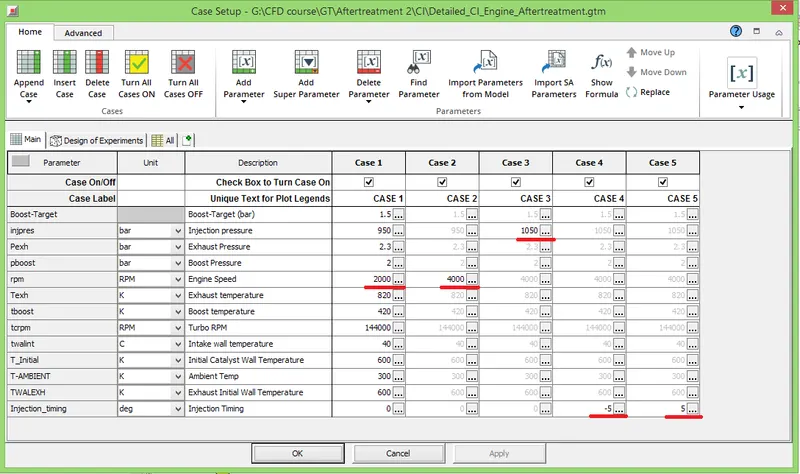
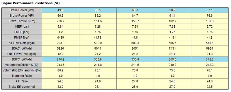
In this case setup Engine speed, injection pressure and injection timing are kept as variable parameters and varied one by one. The other parameters are kept unchanged. It is created in order to check effect of variation on exhaust gases and amount of pollutants at tailpipe.
~Performance parameters:
~Key cylinder properties:
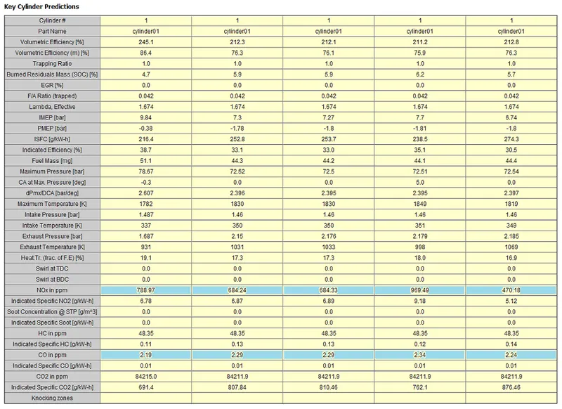
The above figure shows properties of 1st cylinder in each case only.
~Comments on achieved result:
While comparing the cases it is seen from above result figures that with increase in RPM, pollutants like NOx are reduced but CO gets increased which denotes incomplete combustion. BSFC and power both gets increased with increase in RPM. With increase in injection pressure, pollutants like NOx and CO increases slightly. Also, with increase in injection pressure brake power decreases slightly and BSFC increases slightly. With decreasing injection timing (from -5 degree to 5 degree) break power decreases and BSFC increases simultaneously, pollutants like NOx and CO also decreases.
Conclusion:
From above all results it can be conclude that:
- Pollutants like HC can be reduced by increasing Air-Fuel ratio or by reducing injection timing.
- Pollutants like NOx can be reduced by decreasing Air-Fuel ratio or by reducing injection timing.
- Complete combustion reduces HC but increases NOx and CO2.
References:
- Wikipedia
- Paper on exhaust system
- IC Engine book by Heywood
- GT Tutorial guide