Modelling of 25 storey building with the specified properties using ETABS
1. Model Initialization in ETABS:
- Open ETABS software.
- Click on New Model.
- In the New Model Quick Template dialog, select Custom Grid Spacing.
- Click Edit Grid Data and set your custom grid spacing.
- After setting the grid, click OK.
2. Story and Grid Data:
- Under Story Dimension, click Edit Story Data.
- Set the story data for the first three stories, with Story 1 as the master story.
- Right-click on the first column, select Add Story, and click Keep Existing Story Heights.
- Add 22 more stories (to make it a 25-storey building).
- Click OK.
3. Defining Materials:
- Go to Define → Material Properties.
- Add new material for Concrete (Grade M30).
- Add new material for Steel Rebars (Fe 415).
- Click OK.
4. Defining Sections:
Go to Define → Section Properties → Frame Sections.
Click Add New Property for Beam:
- Select Rectangular shape and input beam dimensions: 300 × 400 mm.
Add a new property for Column:
- Input the column dimensions: 800 × 800 mm.
Click OK.
Go to Define → Section Properties → Slab Section.
Select Add New Property for the slab, and set the thickness: 150 mm.
5. Defining Load Patterns and Loads:
- Go to Define → Load Patterns to define the load types.
- Add load cases for Dead Load, Live Load, and Seismic Load.
6. Defining Mass Source:
- Go to Define → Mass Source to assign mass to the building based on the load patterns.
- Define load cases under Define → Load Cases.
7. Creating Load Combinations:
- Go to Define → Load Combinations to create necessary load combinations based on the seismic requirements (dead load, live load, seismic load, etc.).
8. Drawing the Building:
- Quick Draw Columns: Use the Quick Draw Column tool to place columns in the model.
- Quick Draw Beams: Use Quick Draw Beams to place beams.
- Select the first horizontal and vertical beams and use Edit → Replicate to replicate them across the building.
- Draw the slab by selecting Quick Slab, ensuring that the slabs in all stories are similar.
9. Assigning Loads:
- Select all beams and go to Assign → Frame Loads to assign distributed frame loads.
- Select the slabs and go to Assign → Shell Loads to assign uniform shell loads.
- Assign Diaphragm to the slabs by selecting the slabs from the Select tab and using Assign → Diaphragm.
10. Running the Analysis:
- Save the model.
- Click Run Analysis from the analysis panel.
11. Viewing Results:
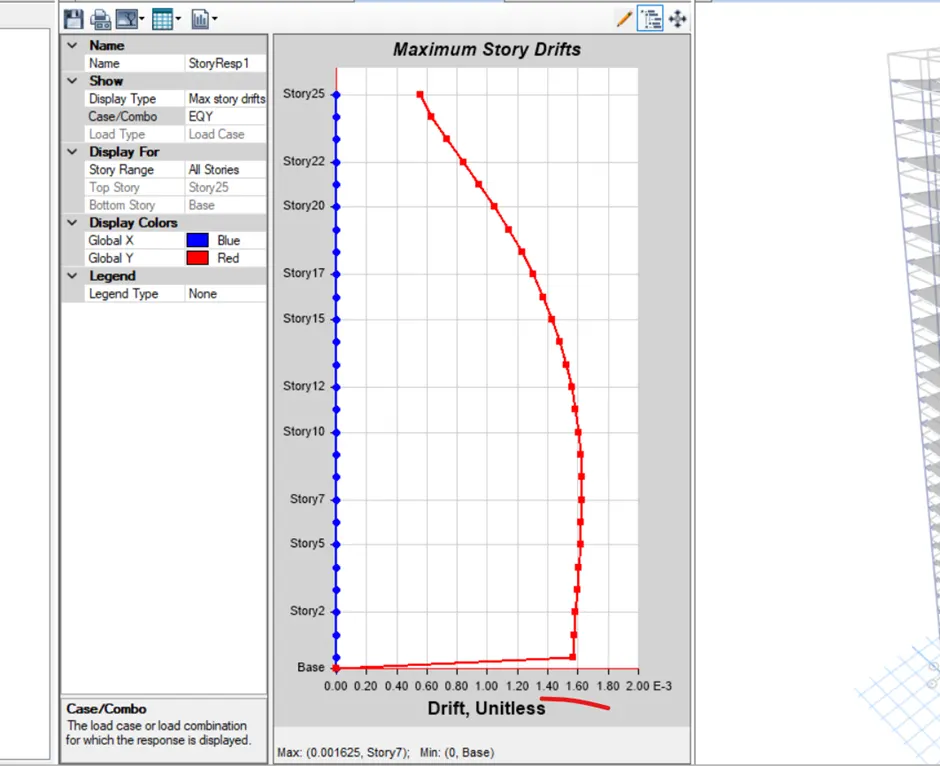
- After the analysis, go to Display → Story Response Plot.
- Change the display type to Maximum Storey Drift.
- Select the desired load combination to view the results.
Verification of Seismic Code Requirements:
- Ensure the building meets seismic design requirements as per IS 1893 (for India) or the relevant seismic code for the region.
- Review the story drift and base shear from the results to verify that the building is in compliance with the seismic codes.
- Check if the structural design and load combinations are in line with seismic force distribution, and validate the column and beam design based on seismic load effects
Given data:
Structural Element Sizes:
- Beams: 300 × 400 mm
- Columns: 800 × 800 mm
- Slab: 150 mm thick
Material Properties:
- Grade of Concrete: M30
- Grade of Steel Reinforcement Bars: Fe 415
Loading details:
- Dead Load on beams from infill wall: 10 kN/m (Let us assume the same for roof floor in view of parapet)
- Live load on floor: 3 KN/m2 (Let us assume the same for roof floor)
- a) Buildings are assumed to be pinned at the base
- b) All columns in all storey are of the same size
- c) All beams in all storeys are of the same size
- d) Building is located on Soil type-II and in Zone-III. Assume other factors if required.
Aim:
To model a 25-storey building using ETABS software and verify the seismic code requirement from ETABS analysis.
Procedure:
- Open ETABS software.
- Click New model.
- Give model initialization setting as follow
- Click ok
- In the new model quick template dialog box , select custom grid spacing and click Edit grid data
- Give the following settings in grid system data dialog box.
- Click ok.
- Select custom story data under story dimension and click edit story data.
- Give the story data for first- three story as follow having story 1 as master story.
- Write click on the first column and select add story and click keep existing story heights.
- Give number of added story as 22.
- Click ok
- The following page opens
- Click Define--> Material properties
- Click Add new material for assigning concrete
- .
- Click Add new material for assigning Rebars
- Click ok
- Click Define--> Section properties--> Frame sections.
- Select Add new property in the dialog box.
- Select the concrete shape as rectangular and give the following settings for the Beam
- Beam property is added.
- Again, click Add new property for creating property for column.
- Column property is added.
- Click--> Section properties--> Slab section
- Select Add new property and give the following settings.
- Clickà Define--> Load pattern
- Define load patterns by its name
- Click Define--> Mass source
- Check load cases by click Define-->Load cases.
- Create load combinations, Define--> Load combinations
- Create Columns by Quick draw column.
- Select quick draw beams.
- Select the first horizontal and vertical beams and go to edit and select replicate.
- Select first floor in plan view
- Draw slab using quick slab by having similar stories in the status
- Select all the beams from select tab
- Assign frame loads as distributed from assign tab.
- Select the slabs
- Assign shell loads as uniform
- Select the slabs from select tab and assign as diaphragm from assign tab.
- Click run analysis in the panel after saving the file.
Result:
- Click Display -->Story response plot. Change the display type to Maximum storey drift and desired combo to see the plots.