Modelling of 25 storey building with the specified properties using ETABS
Aim: Model a 25 storey building on ETABS with structural properties as specified below. Ground floor or plinth floor level can be taken at a height of 1.5 metres from the base. Each of the successive 25 storeys has a storey height of 3 metres.
Given details:
Structural Element Sizes
- Beams: 300 × 400 mm
- Columns : 800 × 800 mm
- Slab: 150 mm thick
Material Properties
- Grade of Concrete: M30
- Grade of Steel Reinforcement Bars: Fe 415
Loading
- Dead Load on beams from infill wall: 10 kN/m
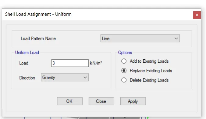
- Live load on floor: 3 kN/m2
Procedure:
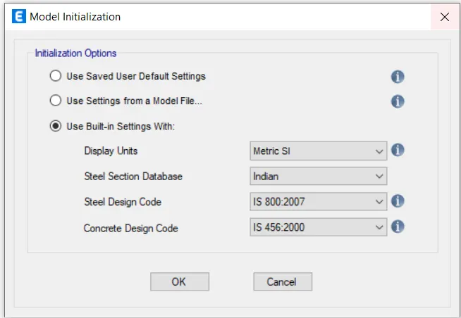
- Open ETABS software, and select new model
- Use the built in settings with
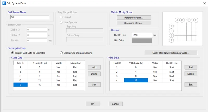
- Give the 5grids in x direction and spacing each 4m
- Give the 4grids in y direction and spacing each 4m
- Click on story data and give the height of each floor.
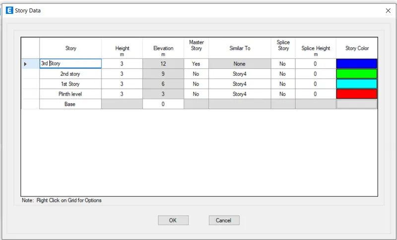
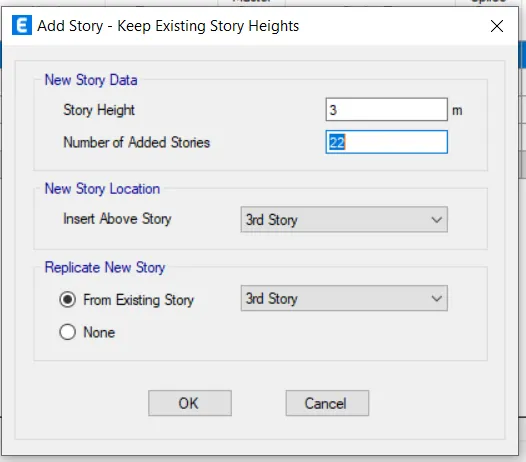
- And assign all story to 1st story.
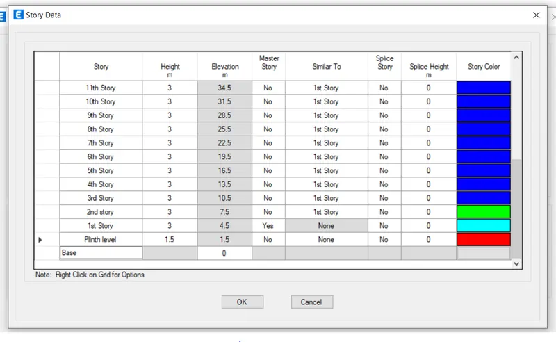
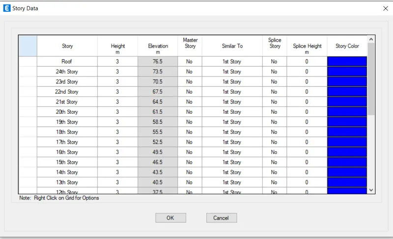
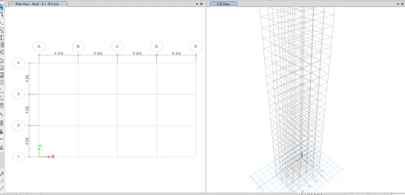
- Know we need to input the material property, for this go to difne tab and select the material properties and add it.
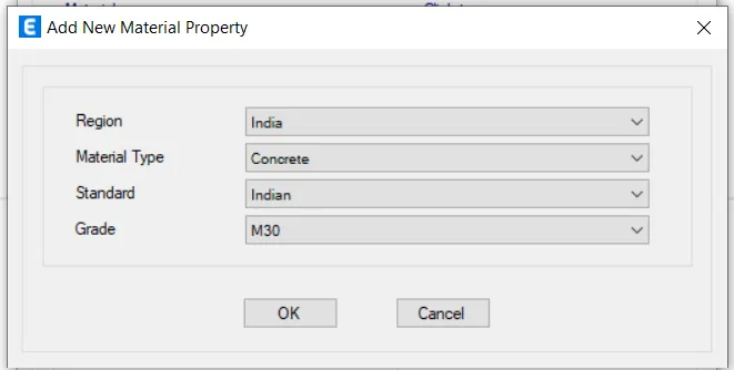
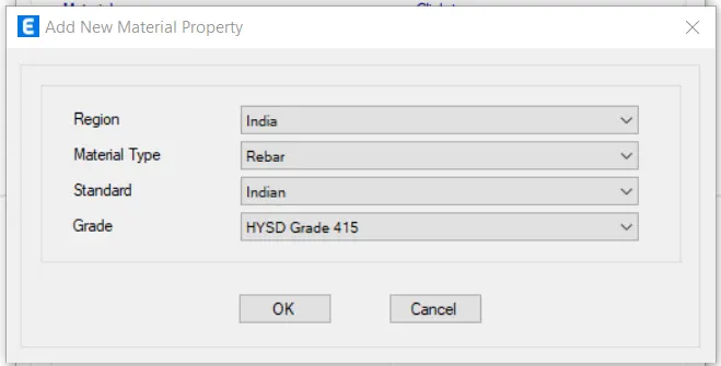
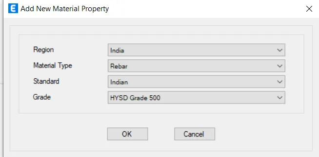
- the material properties are added.
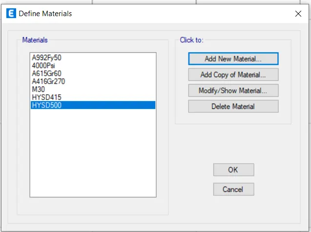
- Now we need to add the frame members of columns, beam, and slabs. Go to define tab and click on selction properties and select frame section.
- And click on add new property and assign name and material type.
- And click on show rebar in that give the rebar for it.
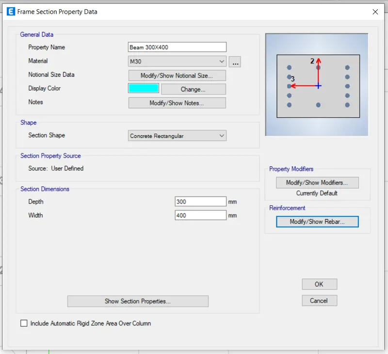
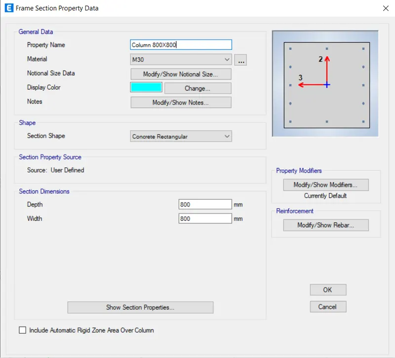
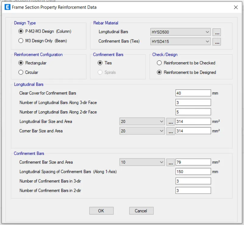
- And beam and column is added.
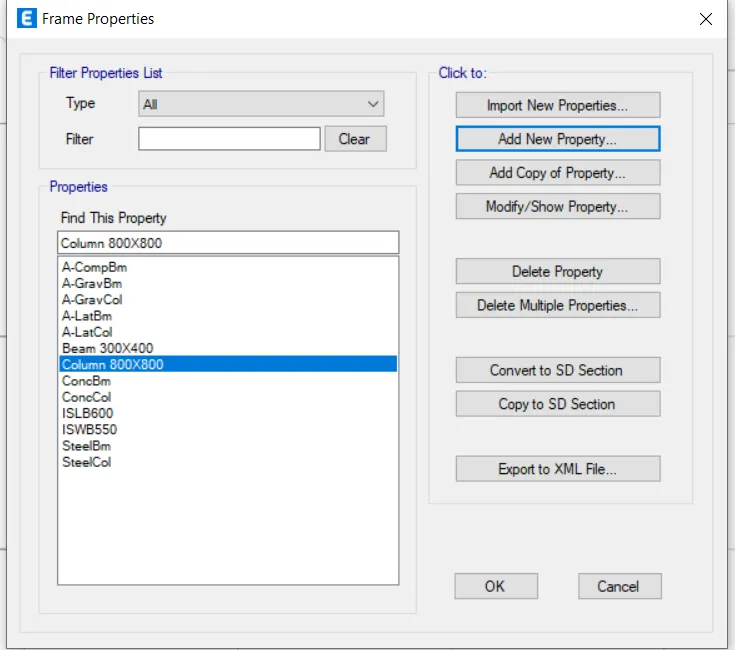
- Go to define tab and click on selction properties and select slab section.
- And assign the thickness for slab.
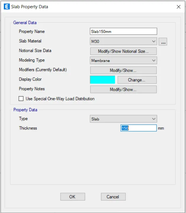
- So all the properties are added correctly. now we need to the structural members.
- Click on quick draw column option and placed the column at the center of grid
- Next, we need to place the beam in position, for this also quick draw beams option can be chosen.
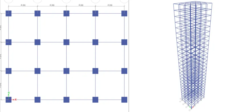
- Now. we need to create the slabs, for this initially change the all storeys option to similar storeys Which may exclude the base and plinth level.
- Then, choose quick draw floor or wall option to easily draw the floor slabs.
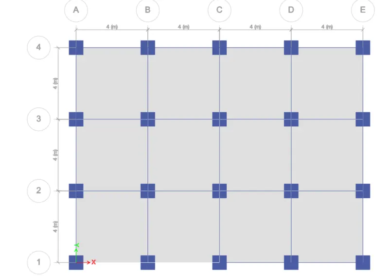
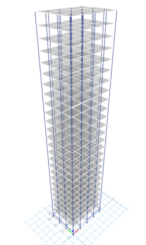
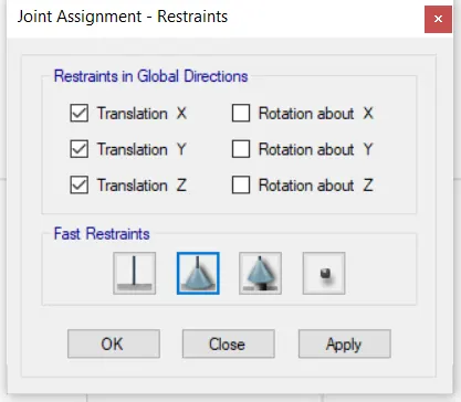
- Go to assign tab and select the Restraints.
- And select the pinned joint.
- Now we need to assign loads to frame.
- Go to define tab and click on load patterns and add the loads
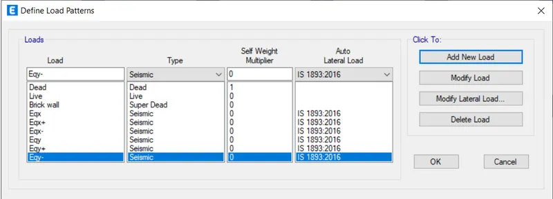
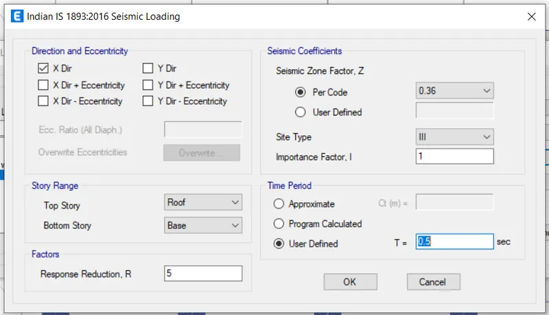
- And modify lateral loads, and click ok.
- Now assign the shell load on the floor and click apply.
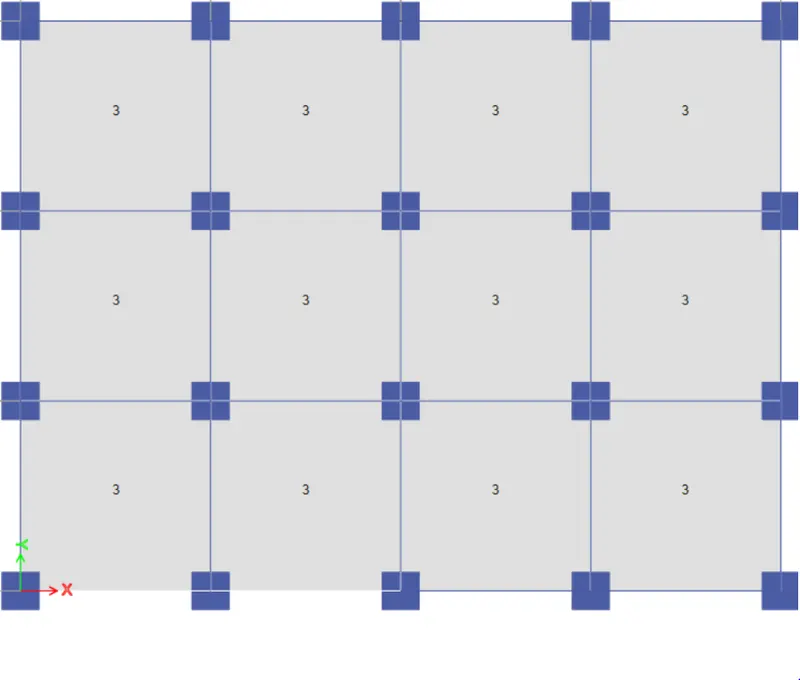
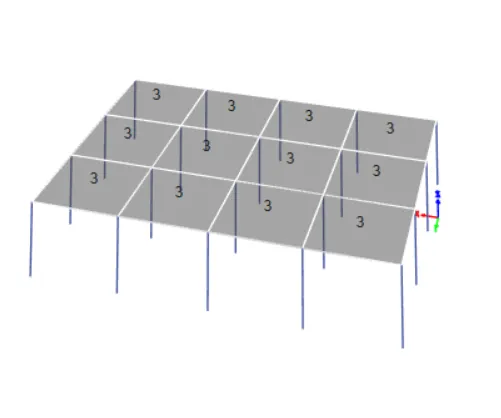
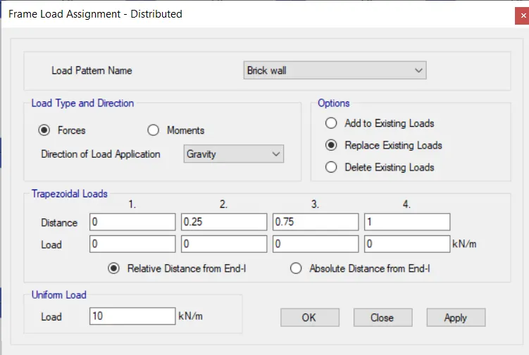
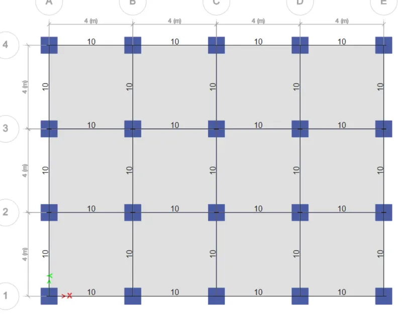
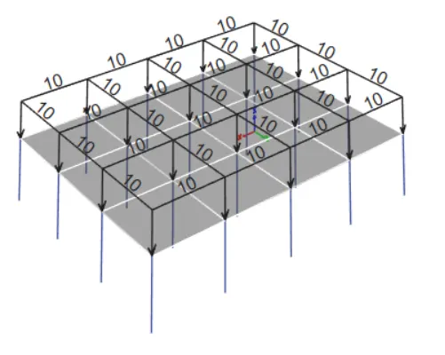
- Now assign the load on beams of brick load.
- And give the load 10KN/M.
- Go to define tab and click on mass sources.
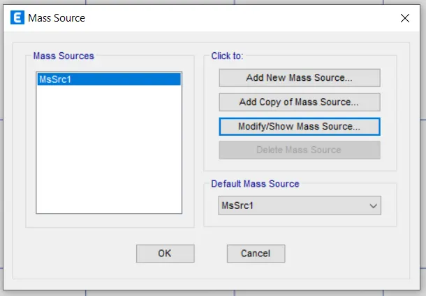
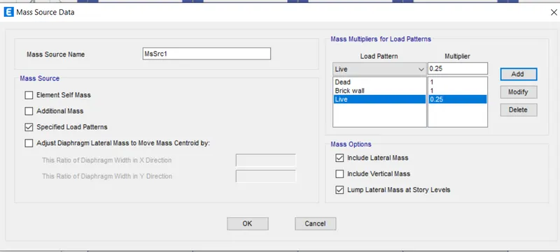
- And click on modify mass sources
- Give the live, Dead, brick load and click ok.
- Go to define tab and click on load combinations.
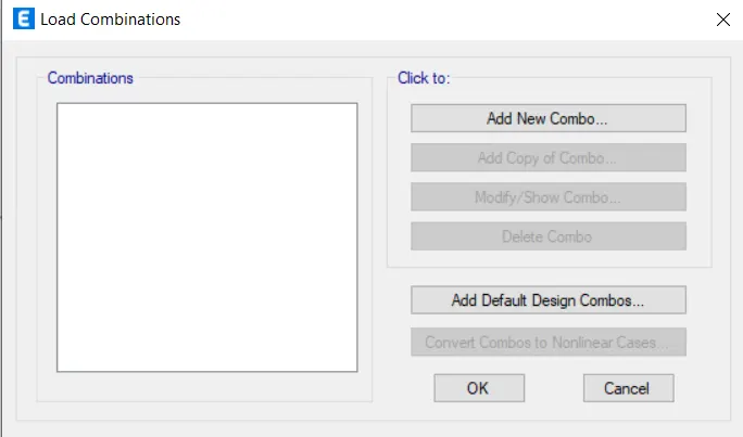
- Click on add default design combinations
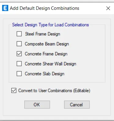
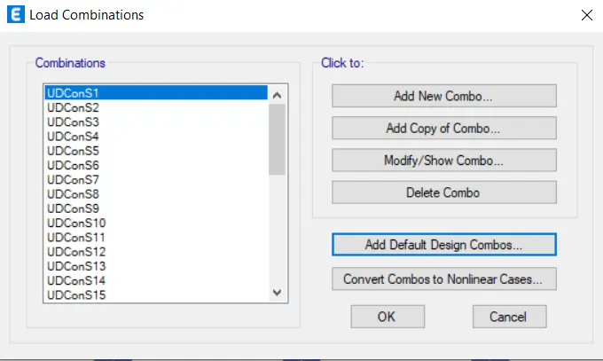
- Select all floors
- And go to assign tab click on shell and select diaphragms.
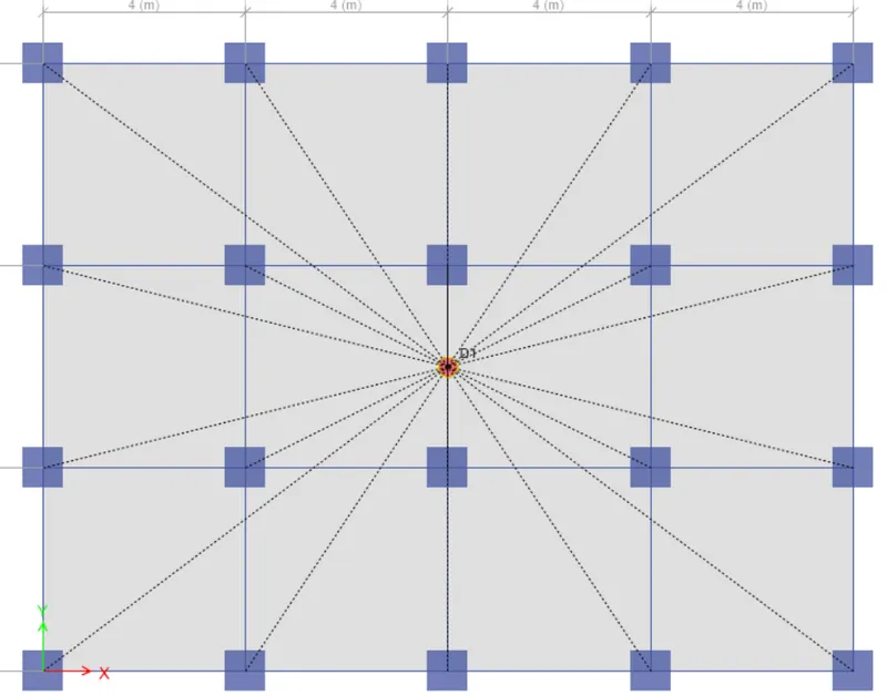
- Go to analyze tab click check model and select all and click ok.
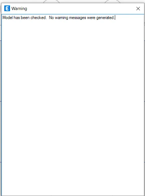
- Go to display tab and click on show table.
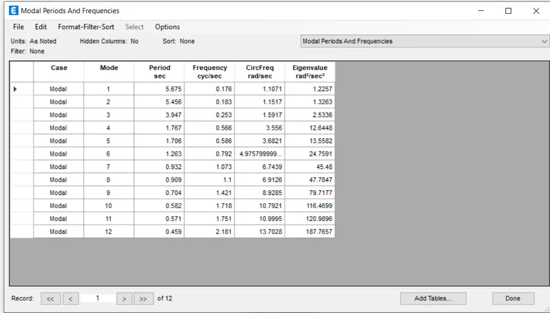
- And select structural output and click on model information and select model period and frequencies.
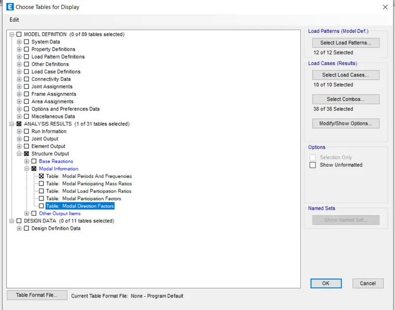
- Modal period and Frequencies
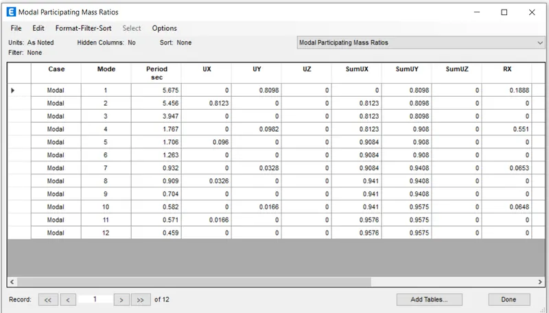
- Modal participating mass ratio
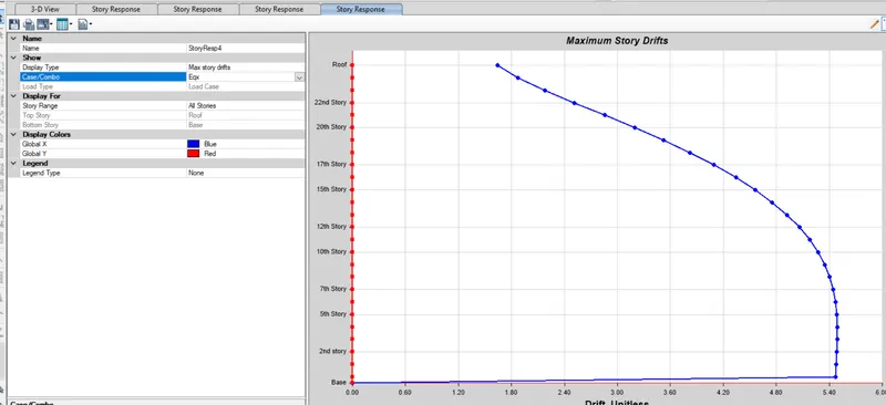
- Go to display tab and select story response plot.