Modelling of 25 storey building with the specified properties using ETABS
1. Aim:
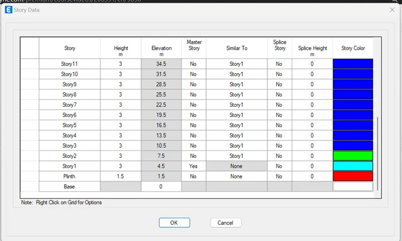
To Modelling a 25 story building on ETABS 2018 with structural properties including Ground floor or plinth floor level at a height of 1.5 meters from the base and a story height of 3 meters.
Procedure:
Step 1:
- Open ETABS 19 application
- Click the File menu and choose to Create a New Model option from there.
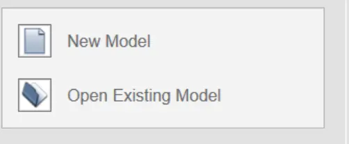
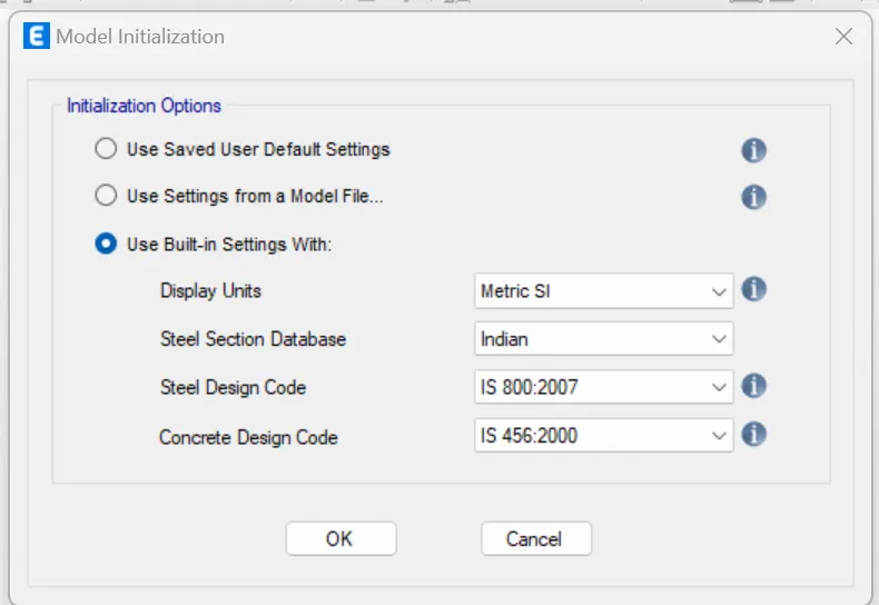
- After choosing a New model a dialogue box will appear which is known as Model Initialization.
- Choose the Built-in settings option and select the display units and codes.
Step 2:
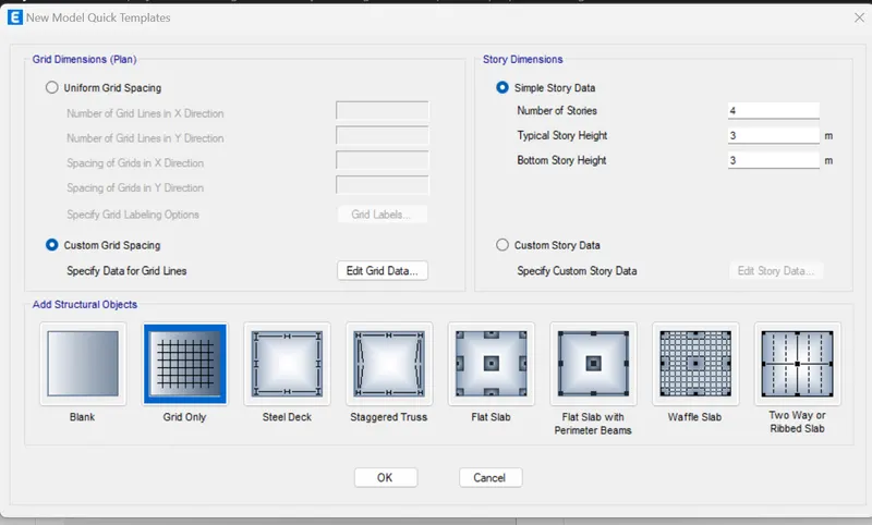
- After the model initialization needs to select Grid and Story inputs from the New model quick templates dialogue box.
- In this dialogue box choose custom grid spacing and custom story data which is used to provide the inputs whatever we want.
Step 3:
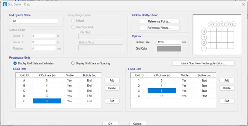
- In the Grid system data dialogue box, set x grid data as 5 numbers at a distance of 4m
- And also set Y grid data as 4 numbers at a distance of 4m.
- Click OK
Step 4:
- In a story data dialogue box, need to input all the relevant details about the story which we want to model.
- Click add a story and add 22 more story
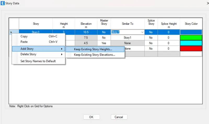
- Put 3m height for all the story except plinth
- Make 1st story as Master story
- Choose all other stories as similar to 1st story
- Click OK
Step 5:
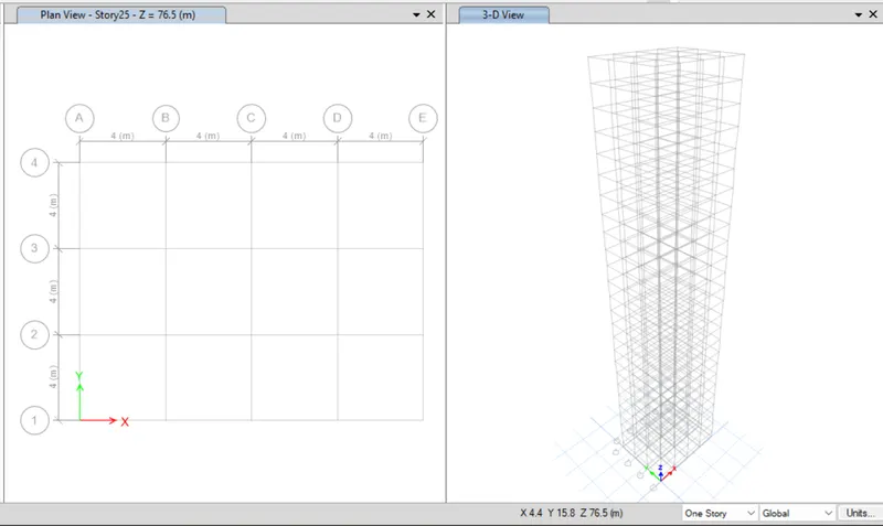
- On the top right corner click the drop-down arrow
- Choose New window option
- Now the screen splits into two.
- Here, we can see the plan and elevation of each story simultaneously.
Step 6:
Applying Properties to Materials
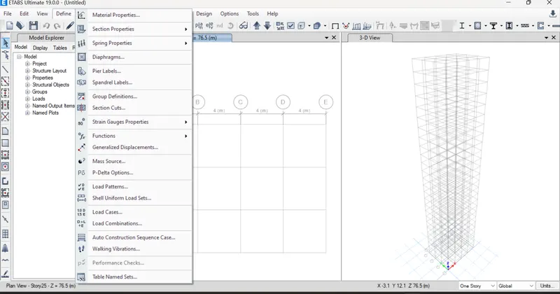
- Click Define tab
- Choose Material properties
Step 7:
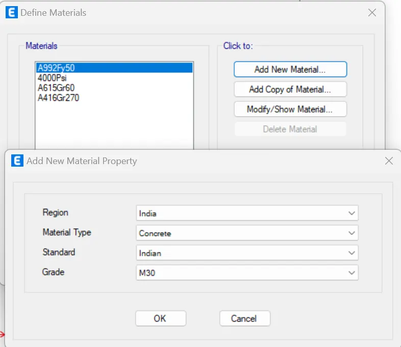
- After selecting Material Properties from the define tab, a dialogue box will appear. In this dialogue box Select the regions as India
- Similarly choose all other inputs like Material type, standard, grade accordingly.
Step 8:
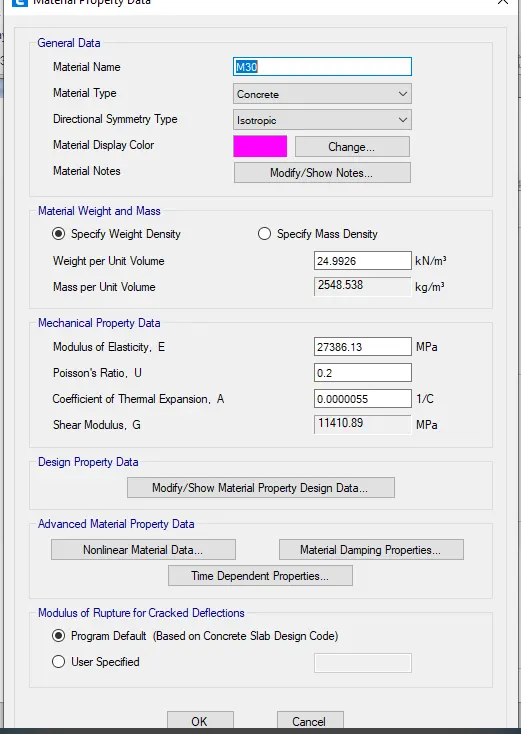
- After clicking ok for Add New Material Property dialogue box it redirects into another dialogue box called Material property data.
- In this data all the relevant data values are assigned default as per IS code which we set previously.
Step 9:
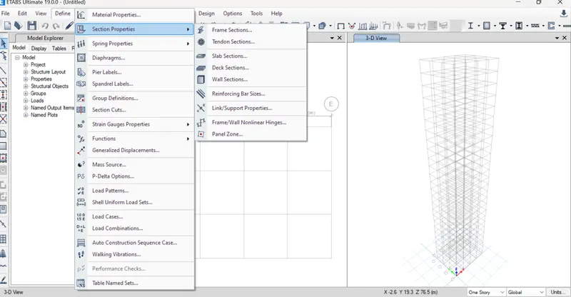
- After applying the properties of Beams and columns we need to apply the property of Slab
- Click Define menu and choose Section properties
- Select Slab Sections
Step 10:
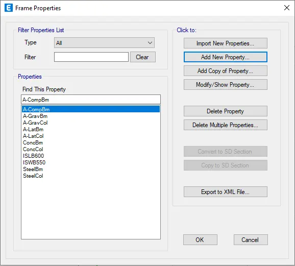
- Click to select Add New Property
Step 11:
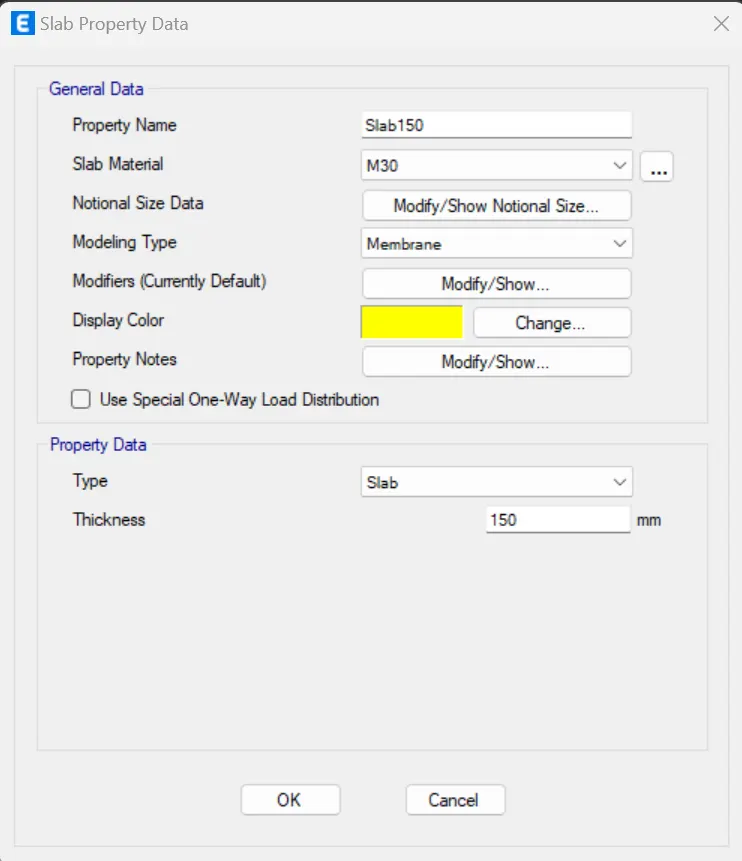
- Rename the Property name
- Select the material as M30
- Choose modeling type as Membrane from the drop-down list
Step 12:
Drawing of Columns and Beams:
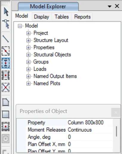
- To drawing the columns and beams in Etabs just click the Quickdraw columns tool in the model tree
- After clicking the tool, the property tab will appear on that tab all the relevant detail about the particular objects will show.
Step 13:
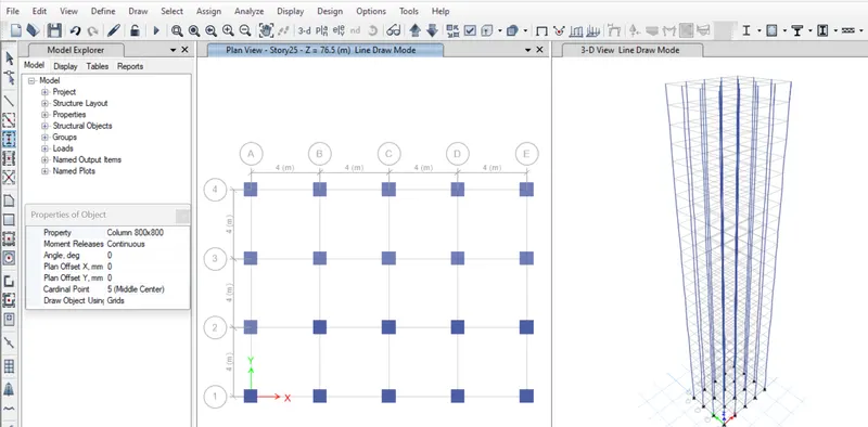
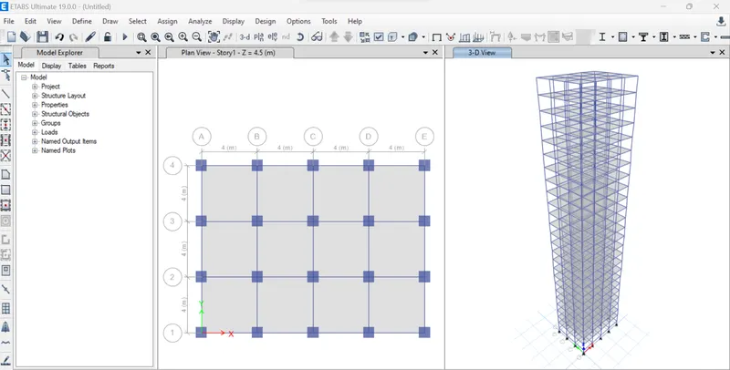
- Draw the Columns in accordance with the grids
- Click the Select object tool to discard the drawing.
Step 14:
Applying Loads:
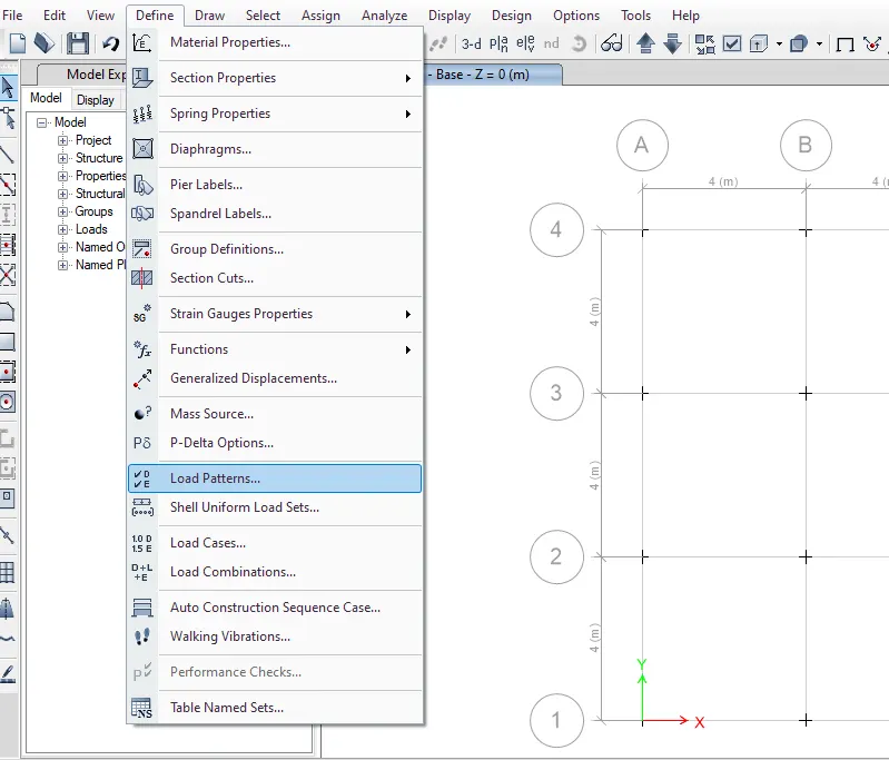
- Click Define tab
- Choose Load Patterns.
Step 15:
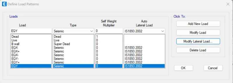
- Add new load as Brickwall, EQX with both positive and negative eccentricity as per IS 1893:2016
- Similarly add EQY with positive and negative eccentricity
Step 16:
- After providing the names and codes of load
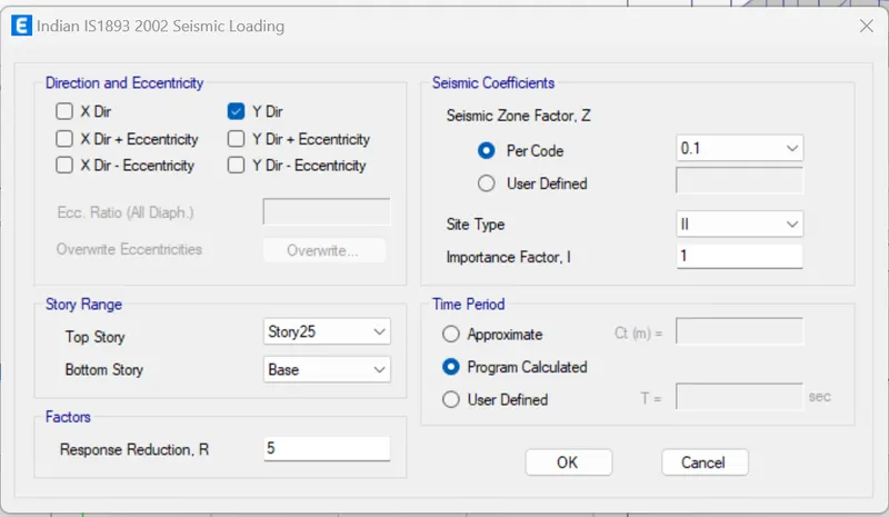
- Click Modify Lateral load option
- Set story rage as a base to top (25th Storey)
- Assume the zone as Zone IV
Step 17:
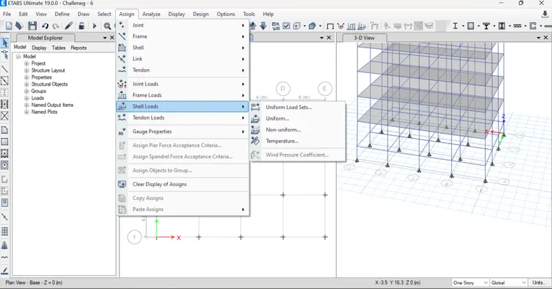
- After providing the load inputs need to assign the shell loads of each story
- Change tab as Similar story
- Select the entire grids
- Click the Assign tab and choose Shell loads
- Select Uniform
Step 18:
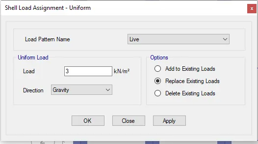
- Choose the load pattern name as already set in the previous step.
- Input the load as 3kn/sq.m as given in the question
- Click ok
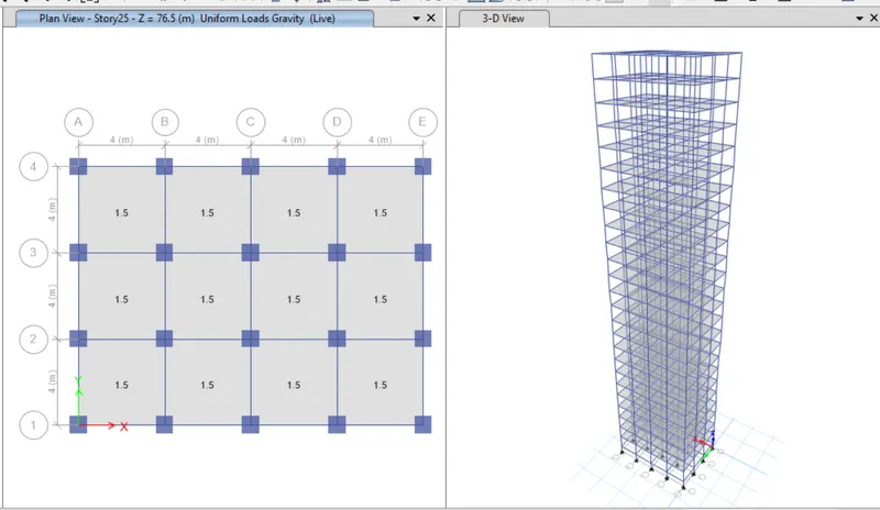
Step 19:
- Similarly we need to assign the live loads for all the beams
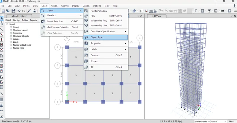
- click the Select tab
- choose object type and select Beam
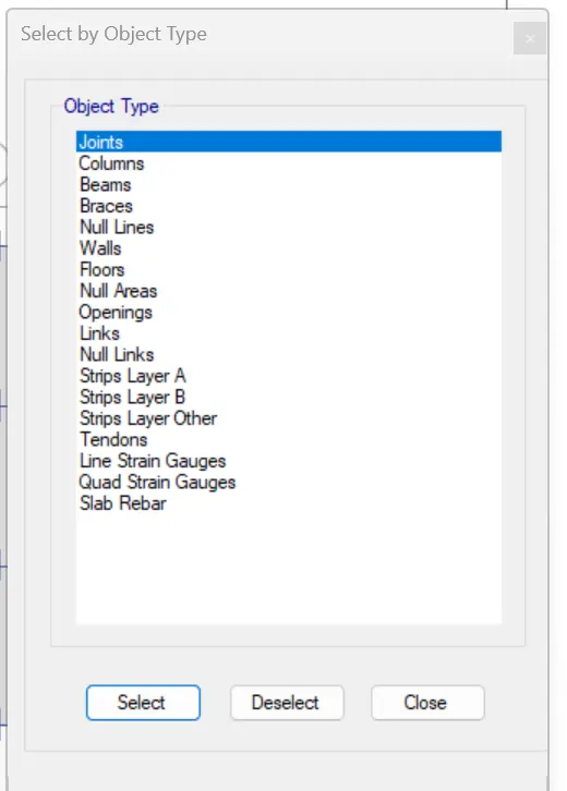
Step 20:
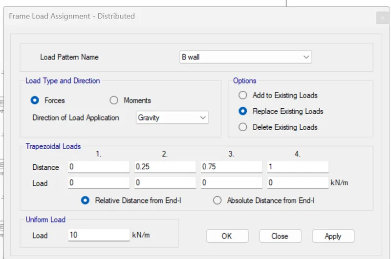
- Choose the load pattern name from the drop-down list
- Set load as 10Kn/sq.m
- Click Ok
Step 21:
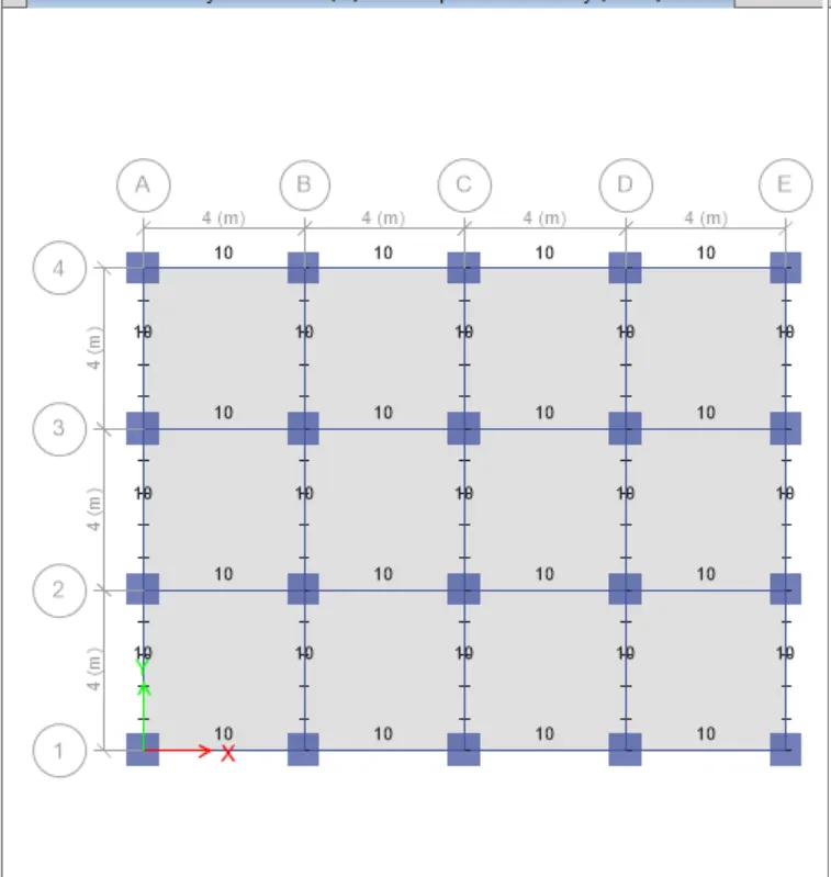
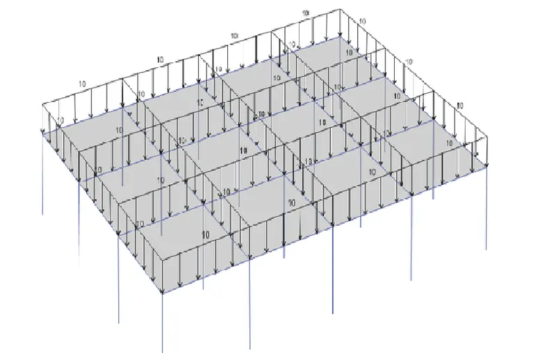
- To view the loads click the toggle option on top of the screen
- And rotate the view where we can see the loads applied.
Step 22:
- Before running the analysis we have to set one more step i.e. Mass Source
- Go to the Define tab
- Select the Mass Source option.
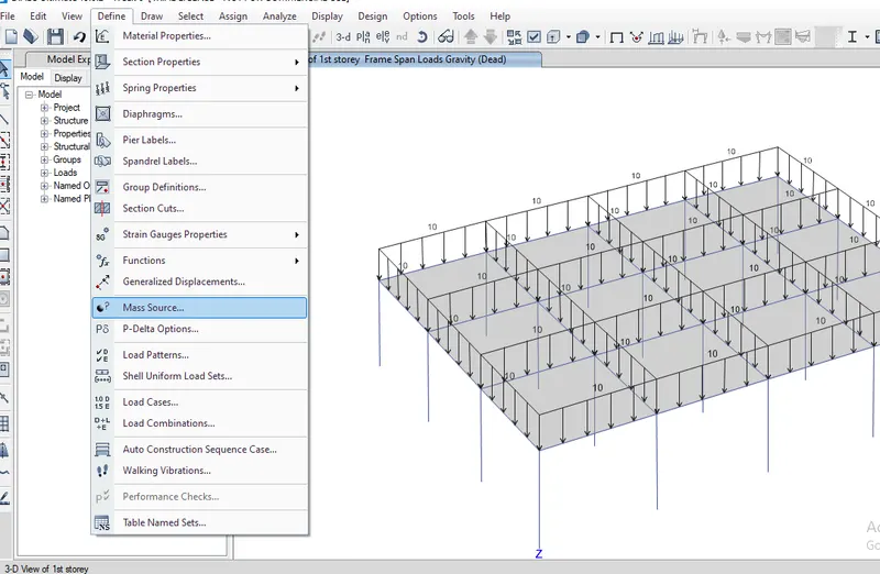
Step 23:
- Tick mark the specified load patterns
- Add the load patterns which we want to assign the model
- Click Ok
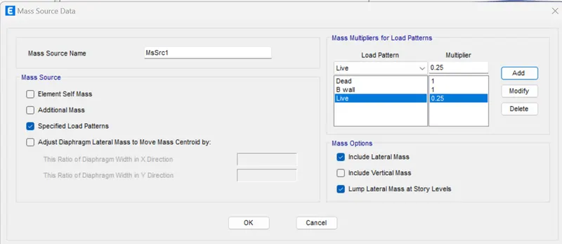
Step 24:
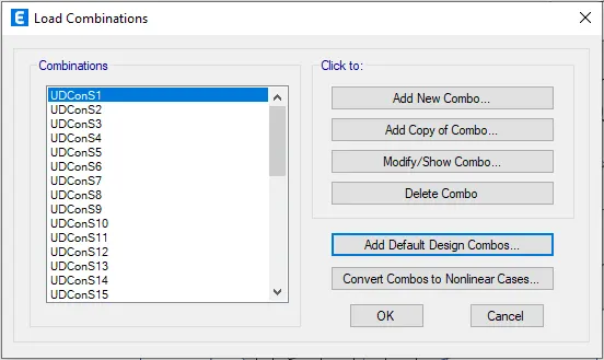
- one of the important steps for modeling is to set load combination
- Click the Define tab
- Select Load Combinations
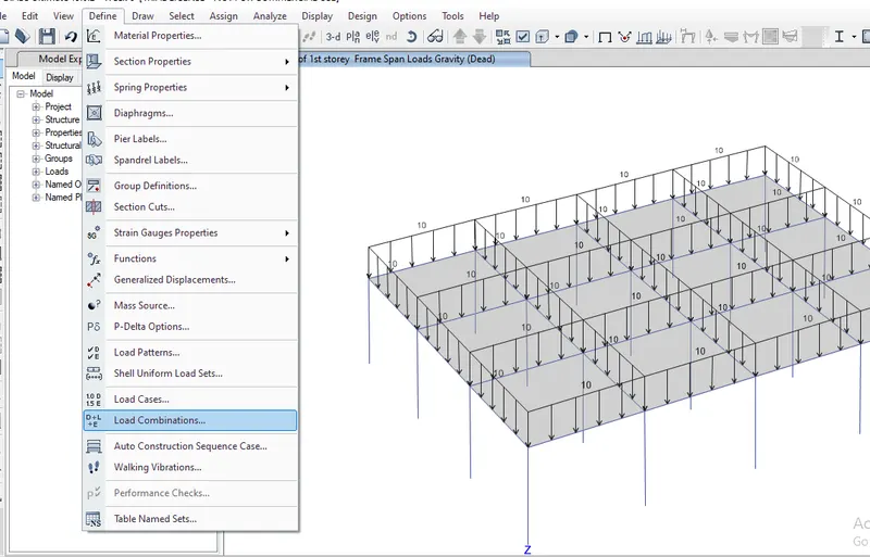
Step 25:
- Choose the load combination
- Select Concrete frame design
- Click Ok
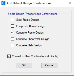
Step 26:
- Immediately ETABS will give you various load combinations as per the code which we are set previously
- Click Ok
Step 27:
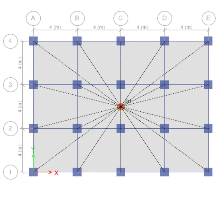
- Final step of analysis is to set Diaphragm
- Click the Assign tab
- Choose shell and select Diaphragm.
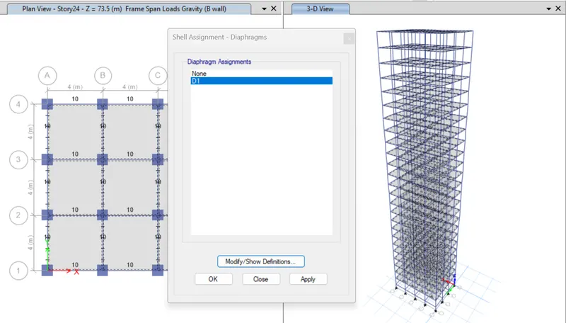
- Choose an all story option from the bottom of the screen
Step 28:
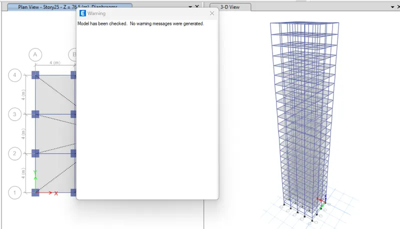
- Click the check tab
- And check the model is there any mistakes. if not go ahead the analysis.
Step 29:
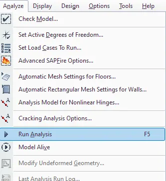
- Now Go to analyze menu->run analysis->analysis will take some minutes
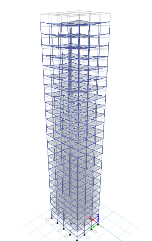
- Go to "Show deformed shape or F6"->Tab will open and select any case(live/dead,earthquake) you want view the deformed shape
Step 30:
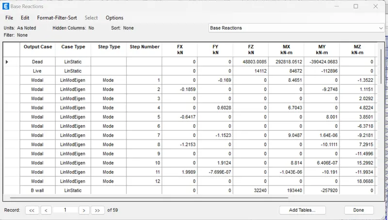
- click on Display menu->Show tables->TAbles display will open
- select anaylysis results->structure output->modal information->Modal participation mass ratios
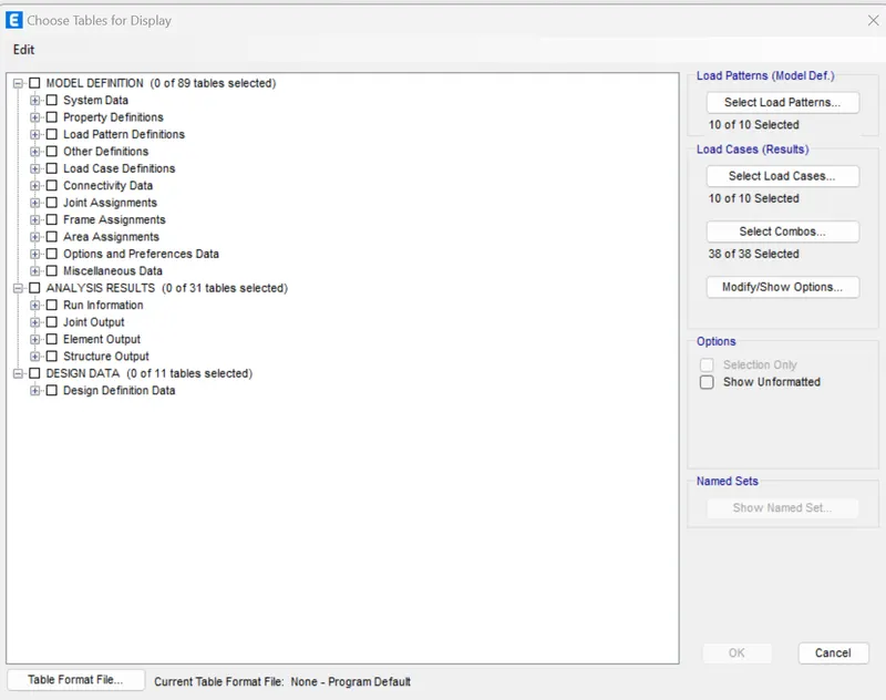
- A Modal participation mass ratios table will appear with all the mass ratios action on the builidng