Modelling of 25 storey building with the specified properties using ETABS
Aim - To model a 25 storey building on ETABS with structural properties.
Introduction -
1) ETABS is an engineering software product that caters to multi-story building analysis and design.
2) Modeling tools and templates, code-based load prescriptions, analysis methods and solution techniques, all coordinate with the grid-like geometry unique to this class of structure.
3) Basic or advanced systems under static or dynamic conditions may be evaluated using ETABS.
4) For a sophisticated assessment of seismic performance, modal and direct-integration time-history analyses may couple with P-Delta and Large Displacement effects.
1) Structural Element Sizes
i) Beams - 300 × 400 mm
ii) Columns - 800 × 800 mm
iii) Slab - 150 mm thick
2) Material Properties -
i) Grade of Concrete - M30
ii) Grade of Steel Reinforcement Bars - Fe 415
iii) Dead Load on beams from infill wall: 10 kN/m (Let us assume the same for roof floor in view of parapet)
iv) Live load on floor: 3 kN/m2 (Let us assume the same for roof floor)
a) Buildings are assumed to be pinned at the base
b) All columns in all storey are of the same size
c) All beams in all storeys are of the same size
d) Building is located on Soil type-II and in Zone-III. Assume other factors if required.
Procedure -
Step 1)
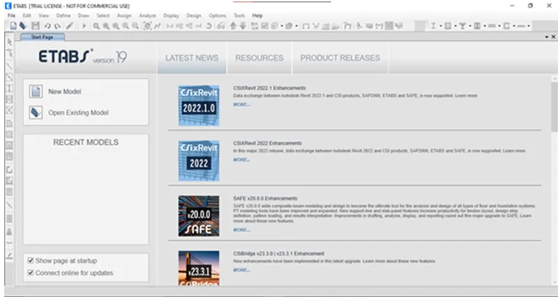
i) Open the Etabs software from deskstop icon
ii) Once software is open - Click on New model
Step 2)
i) Once you click on New model
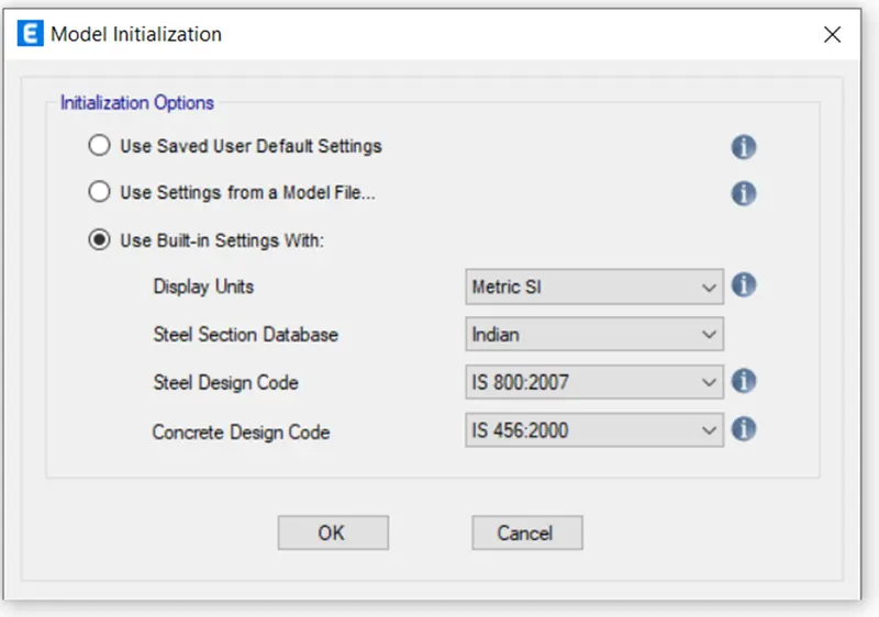
ii) A Model Initialization setting will open
iii) Select - Metric SI units
iv) Select section database - Indian
v) Select Steel code - IS 800-2007
vi) Select Concrete design code - IS 456-2000
Step 3)
i) Once you click Okay
ii) A following dialog box of grid settings will open
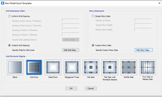
ii) In New Model Quick templates under grid dimensions select the custom grid spacing
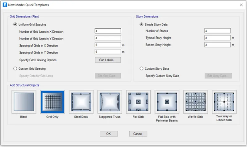
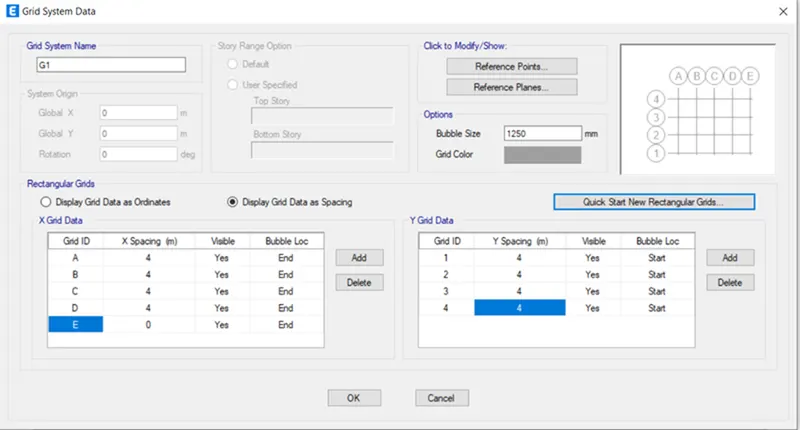
iii) Once you click on Custom grid spacing
iv) Click on Display grid data as spacing
Step 4)
i) In New Model Quick templates under Story dimensions
ii) Select the custom story data and then click edit story data.
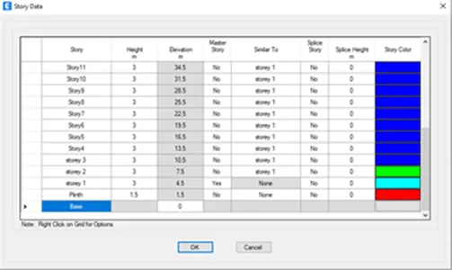
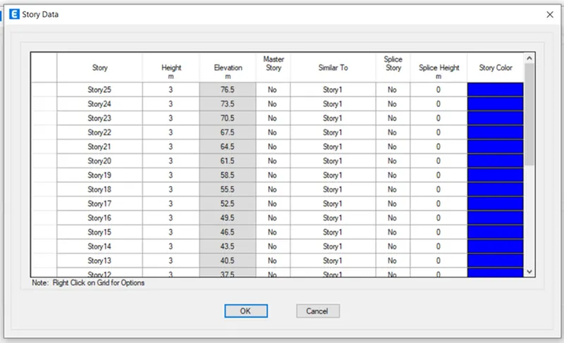
iii) Now input the storey details
iv) As given in question and Story 1 was selected as the Master story
v) And was applied to rest story from 2nd story to roof
vi) Click on Okay.
Step 5)
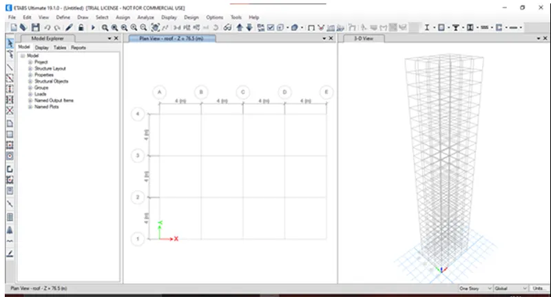
i) Once you click on Okay
ii) A plan and 3D view of model is created in model space
Step 6)
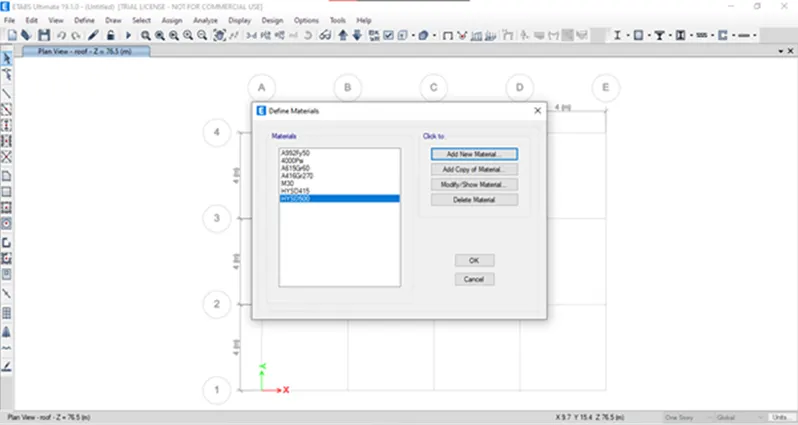
i) Now we have to define the materia properties
ii) Click on Define
iii) Click on Material properties
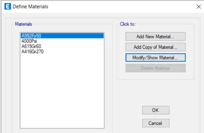
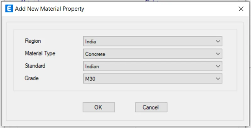
iv) Add New material as Concrete
v) Select Grade of conccrete - M30............................( given)
vi) Standard as Indian
vii) Click on Okay .
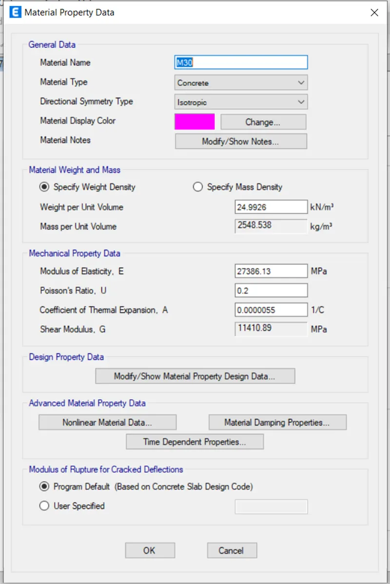
viii) Click on okay
ix) The remaining data is as per IS code
Step 7)
i) Similarly we have to define the materia properties for Steel
ii) Click on Define
iii) Click on Material properties
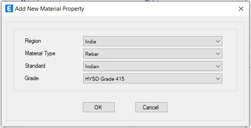
iv) Select New material as Rebar
v) Select Grade of Steel - HYHD - Grade Fe415...................... ( given)
vi) Standard as Indian
vii) Click on Okay.
viii) Click on Okay
ix) The remaining data is as per IS code
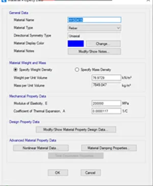
x) Material properties is added
Step 8)
i) Now we have to Define the section properties ( Column and Beam )
ii) Click on Define
iii) Select - Section properties
iv) Click on Frame Section
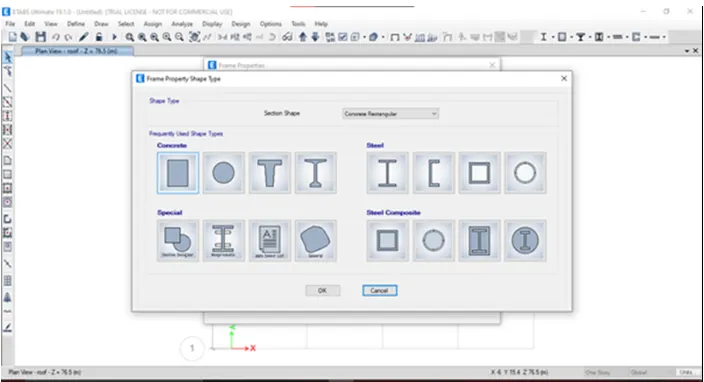
v) Click on Concrete - Rectangular
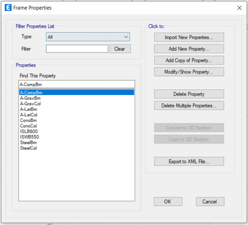
vi) Click on Add new property
vi) Give property name - Beam 300x400............( given)
vii) Material type - M30
viii) Section Shape - Concrete Rectangular
ix) Depth - 400 mm
x) Width - 300 mm
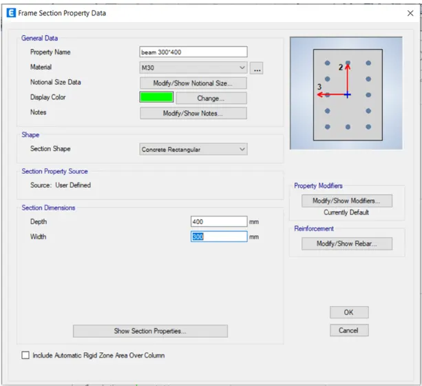
xi) Click on Modify / show Rebar
xii) Select M3 Design Only (Beam)
xiii) Select the rebar materials as HYHD Fe415 in both the direction
xiv) Click on okay.
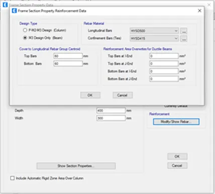
xv) Similarly we have to follow the same steps for Column also.
xvi) Property name - Column 400 x 400 mm
xvii) Material - M30
xviii) Depth - 400 mm
xix) Width - 400 mm
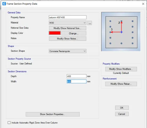
xx) Click on Modify / show Rebar
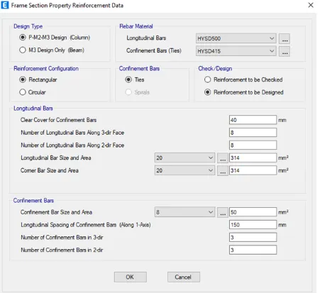
xxi) Select M3 Design Only (Column)
xxii) Select the Rebar materials as HYHD Fe415 in both the direction
xxiii) Click on okay .
Step 9)
i) Now we have to define Slab properties
ii) Click on Define
iii) Select Section Properties - Select Slab properties
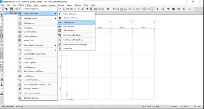
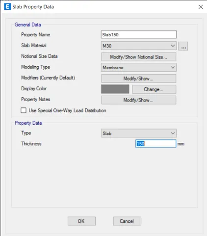
iv) Click on Slab Section
v) Give property name - Slab 150
vii) Modeling Type - Membrane
viii) Type - Slab
ix) Thickness - 150 mm
Step 10)
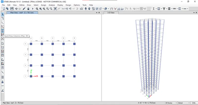
i) Now we have keep the 3D view also to see the properties
ii) Now we have to add the columns and beams
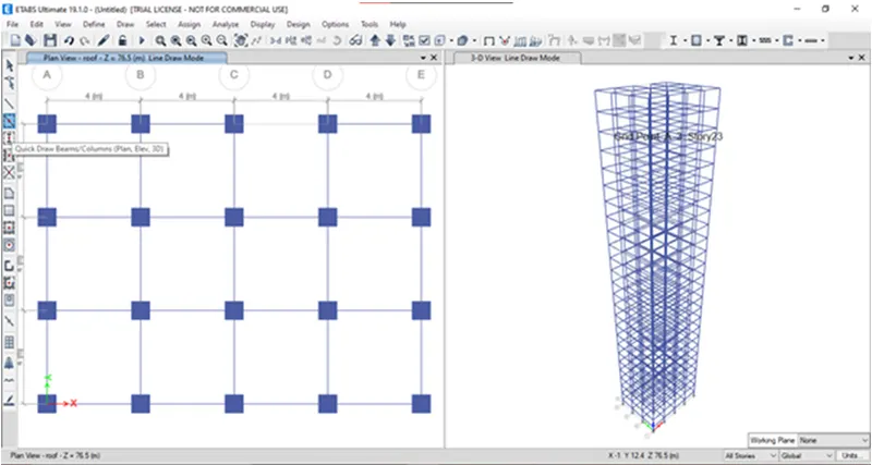
iii) Click on Quick Draw Column option
iv) Select the Column properties which we have defined earlier
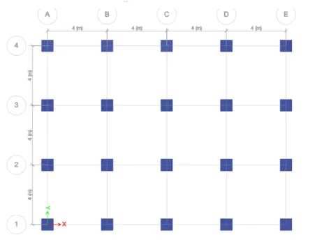
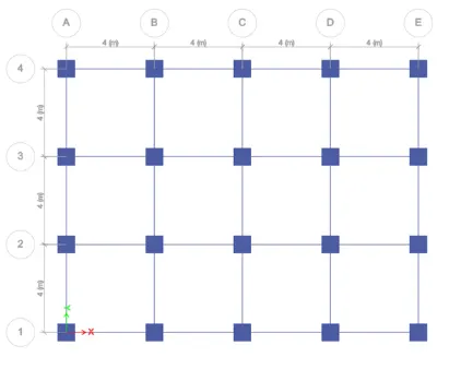
v) Draw the columns at the grids as shown in below
vi) Note that - All stories option should be selected which is at the Bottom
vii) Similarly we have to draw beams also
viii) Select Quick Draw Beam option
ix) Select the Beam properties which we have defined earlier
x) Draw the beam as shown below
Step 11)
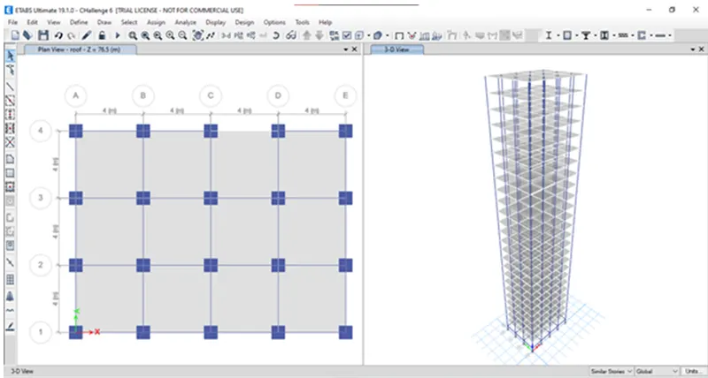
i) Now we have to add the slabs
ii) Select Quick draw floor
iii) Draw the slabs as shown below
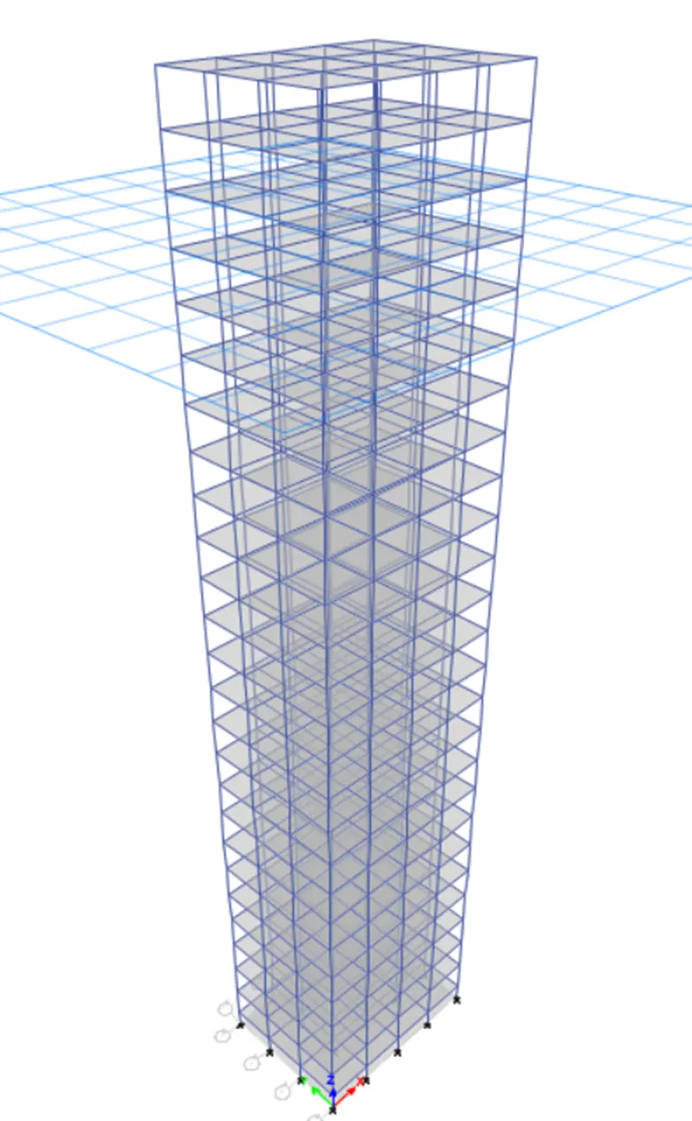
iv) 3D view after assigning the material and section properties
Step 12 )
i) Now we have to assign the base connections
ii) Base connection is given as Pinned type
iii) Click on Assign - Select Joint - Select Restraints -
iv) Select 2nd one - Pinned type
v) Before that - Go to Plinth level - Change the All storey option to One storey as shown below
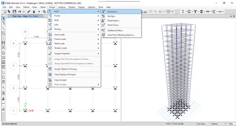
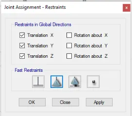
vi) Click on Okay.
Step 13)
i) Now we have to assign the loads
ii) Select Define
iii) Click on load patterns
iv) Define load pattern dialogue box will open
v) Add the Following loads and Select the IS code for Seismic Case as IS -1893
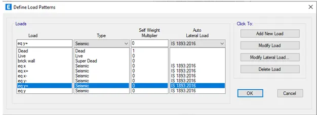
vi) Following Modification needs to be done in case of Seismic load
vii) Select Zone factor - Zone III - 0.24 ..............................................( given)
viii) Select Soil type - Type II ............................................................( given)
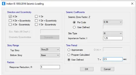
ix) Follow the same for remaining seismic directions
Step 14)
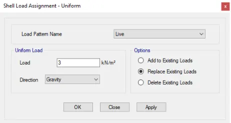
i) Now we have to apply the live loads.
ii) In Assign menu- Select Shell Loads
iii) Click on Uniform loads
iv) Load Pattern as - Live load
v) Load - 3 Kn/m^2
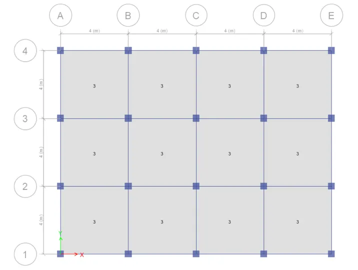
vi) We can see that Floor load has been assigned to all the floors
vii) Now we have to assign Brick wall load for beams
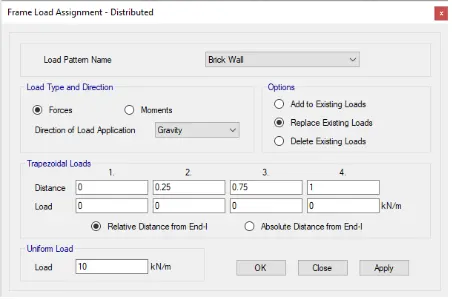
viii) Select Assign
ix) Click on Frame loads - Uniformly Distributed loads
x) Select load pattern as Brick wall
xi) Apply 10 Kn/m load ........................................................(given)
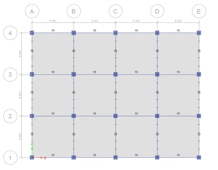
xii) Load has been assigned
Step 15)
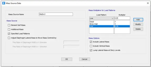
i) Now we have to assign Mass source for Modal calculations
ii) Click on Define menu
iii) Select mass source options
iv) Mass source dialogue box will open
v) Add the loads
vi) Dead load - 1
vii) Brick wall - 1
viii) Live load - 0.25 ( Because we only considered some fraction of Live load in calculation of seismic weight )
So live load , upto 3 Kn/m2 - 25%
above 3 Kn/m2 - 50%
Step 16)
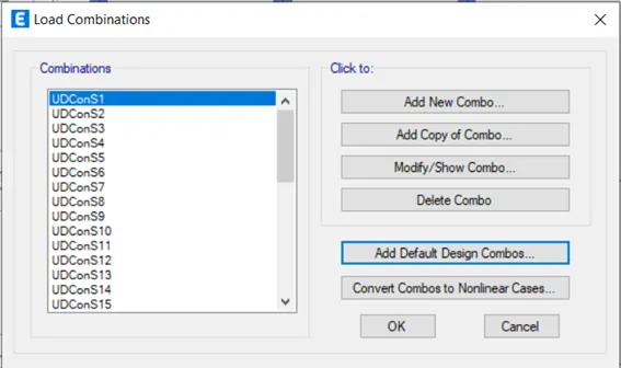
i) Now we have to assign Load combinations
ii) For that Click on Define menu
iii) Select Load Combinations
iv) Load Combination box will open
v) Click on Add Default Design Combos
Step 17 )
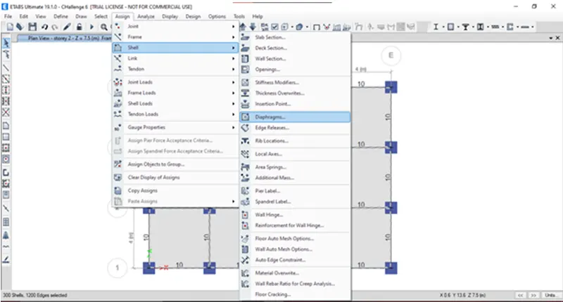
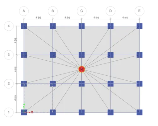
i) Now we have to assign Diaphragm
ii) Click on Assign
iii) Select Shell - Select Diaphragm
iv) Select D1
v) Click on Apply
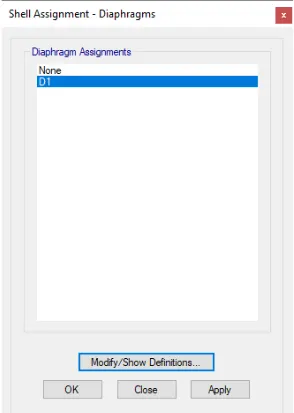
vi) Click on Ok
vii) A Diaphragm has been assigned
Step 18)
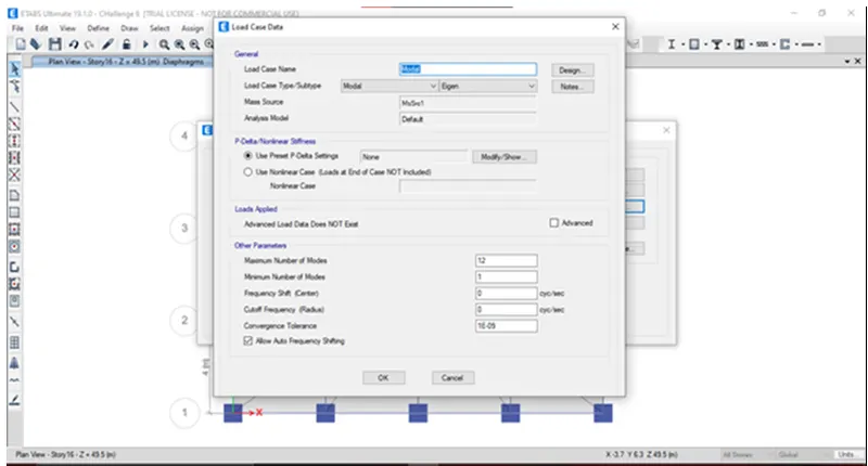
i) Now we have to create a Modal Analysis
ii) Click on Define
iii) Select Modal cases
iv) Click on Modify
v) Load Case Name - Modal
vi) Load case type - Eigen
vii) Mass Source - Which we have already defined
viii) Click on Okay
Step 19)
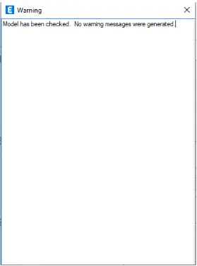
i) Before Run Analysis we have to check the model
ii) Click on Analyze
iii) Click on Check Model
iv) A structure is verified without any error and Model has been checked .
Step 20)
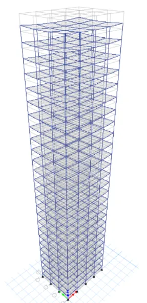
i) Now Click on Run Analysis
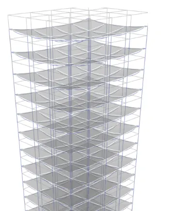
ii) Once the analysis is done you will see the deform shaped as below
Step 21)
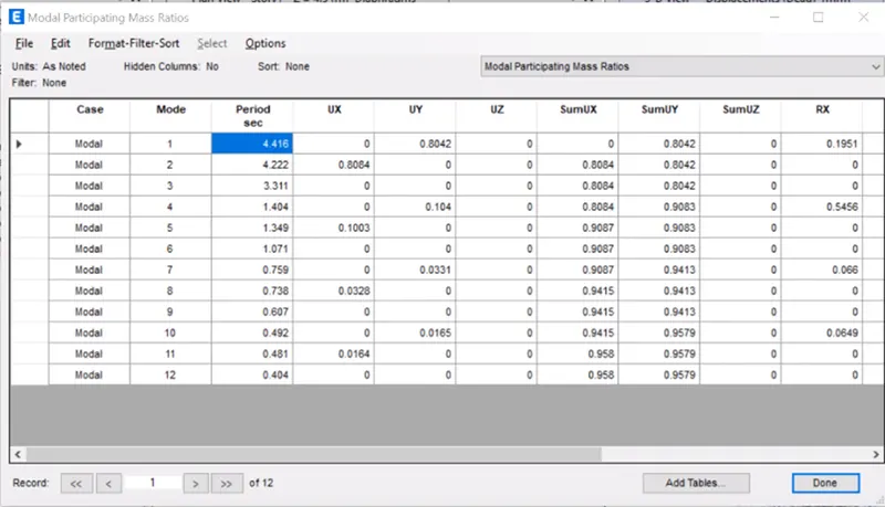
i) Now we have to check the mode as per IS 1893 .
ii) For that click on Display - Show tables
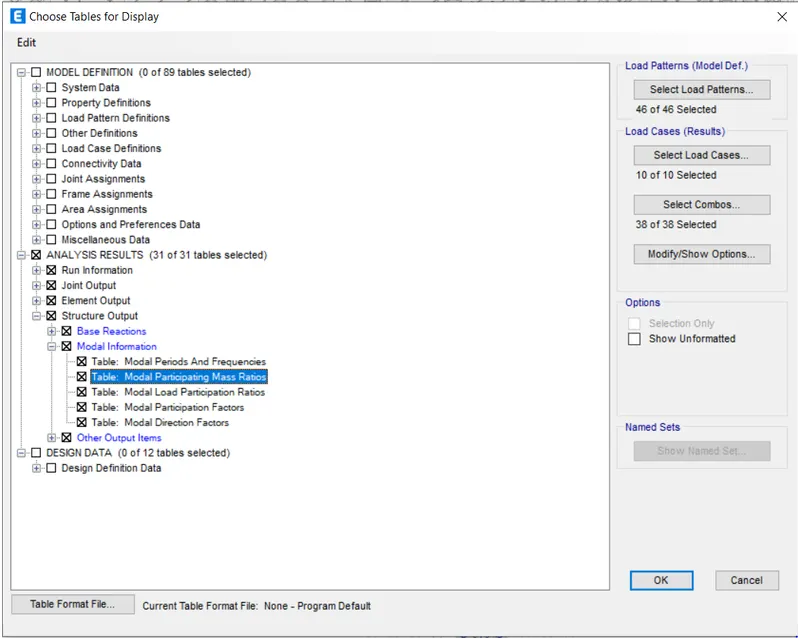
iii) Click on Analysis Result - Select Structural Output
iv) Select Modal Information - Modal Participation and Mass ratio
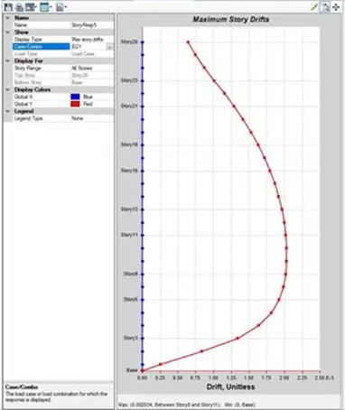
v) For we have to see the Results of storey drift for Base shear case(EQX or EQY)
vi) Click on Display -Storey response plot
vii) Keeping load case to EQY and selecting max story drift the Maximum drift value is 0.0020
Results -
i) The modeling of G+25 storey has been completed and successfully Analyzed
| Parameters | Checks AS per IS 1893 | Results | |
| Fundamental Translation Natural Periods | X - Direction | Tx = 4.4 seconds ( given) | 4.416 seconds |
| Y - Direction | Ty = 4.2 seconds ( given) | 4.222 seconds | |
| Torsional Irregularity |
IS 1893-2016 ( part 1) TAble 5 |
The natural period corresponding to the torsional mode of oscillation must be less than the two fundamental translational modes of oscillation along each principal plan directions. |
Torsional Mode of Oscillation is less than the two fundamental modes of Oscillation i.e Mode 1 = 4.416 Mode 2 = 4.222 Mode 3 = 3.311 |
| Vertical Irregularity |
IS 1893-2016 ( part 1) TAble 6 Clause 7 |
The first Three modes together should contribute at least 65% in mass participation factor in each principal direction |
As we could see that 1st Mode itsel contribute more than 65% i.e Mode 1 = 80% Hence Safe . |
| Fundamental lateral natural periods in two principal plane direction are away from each other by atleast 10% |
As we could see that 1st two modes are not separated each other by 10% i.e Mode 1 = 4.416 Mode 2 = 4.222 Difference is not more than 10% Hence Rechecked |
||
| Inter Storey Drift |
IS 1893-2016 ( part 1) Clause 7.11.1.1 |
Storey drift shall not exceed 0.004 times the storey height under tha action of base shear Vb with no load factors |
As we could see that the Storey drift is less than 0.004 i.e 0.0020 Hence okay. |