Modelling of 25 storey building with the specified properties using ETABS
AIM:
Model a 25-storey building on ETABS with structural properties and to know modeling of a high rise building in ETABS software and to verify the seismic code requirements from ETABS analysis
INTRODUCTION:
By using ETABS software, analyse the building of 25-storey and see how a building behaves under various loads.
PROCEDURE:
STEP1) Install and Launch ETABS 2020
- Install the ETAB software from CSI Website
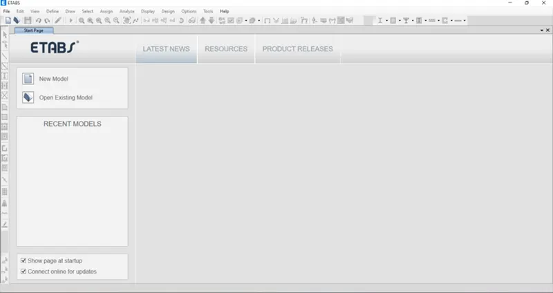
- After complete the installation, Launch ETABS 2020 software from windows
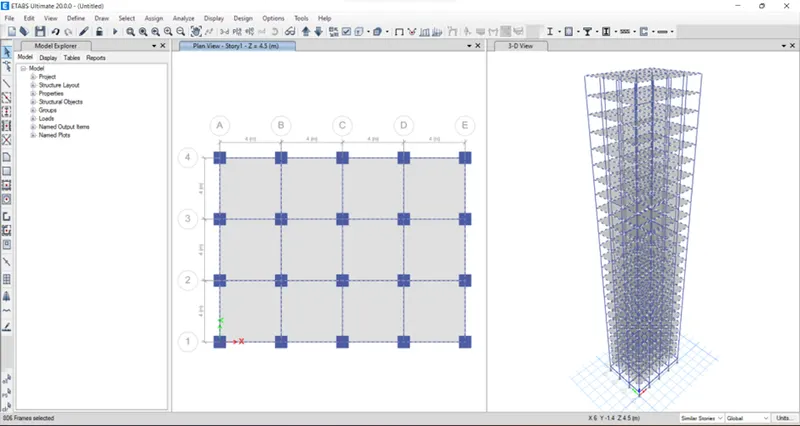
- ETABS home interface will be open as shown below
STEP2) Create New Model
- Click on New Modal from ETABS home interface
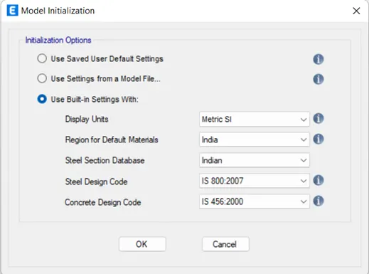
- Select Unit Built in Setting from Modal Initialization dialog box
- Change display unit as METRIC SI
- Region for default material as INDIA
- Steel selection database INDIAN
- Steel design code IS-800:2007
- Concrete design code IS-456:2000 enter OK
STEP3) Create Grids
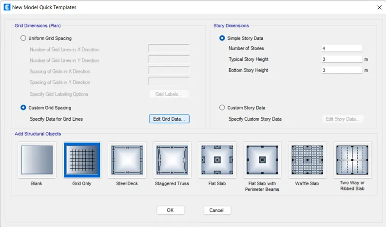
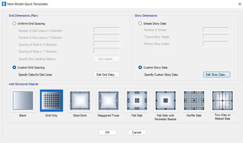
- A new dialog box opened as New Modal Quick Templates
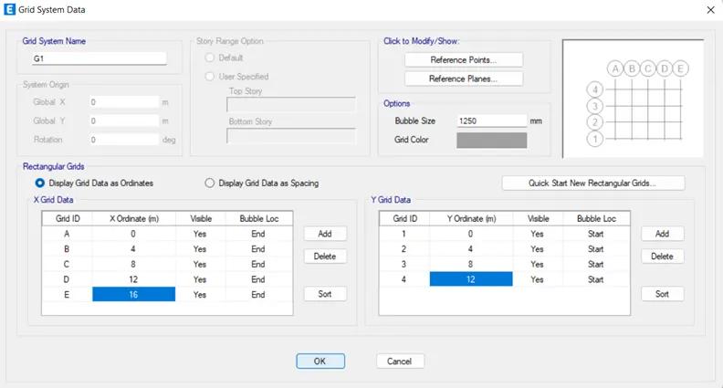
- Select Custom Grid Spacing and click on the Edit Grid Data
- Modify the X & Y Grid Data from the Grid System Data dialog box and click OK
STEP4) Add Building Storey
- Select Custom Story Data and click on Edit Story Data
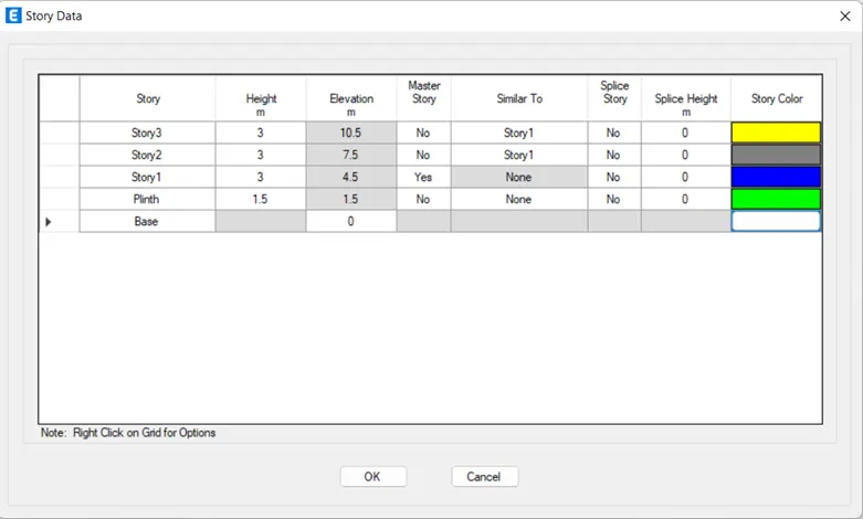
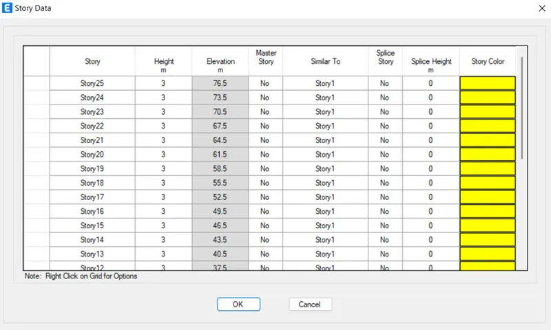
- A new dialog box open as Story Data
- Rename the levels of the story 1,2 3,4 as plinth and story 1,2,3 respectively
- Only plinth level height is 5 and all other story height is 3
- Story 1 as master story so, select yes, towards the story 1
- Change story 2 & 3 similar to story 1
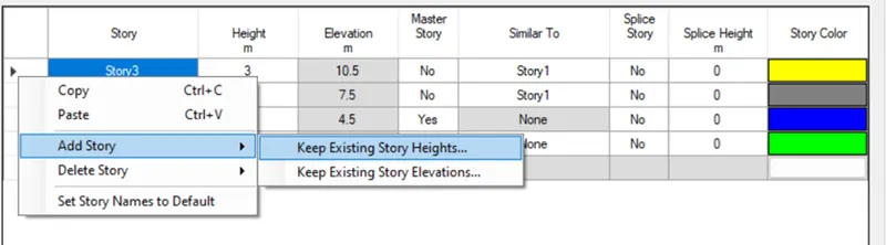
- To add more story above the story 3, right click on story 3 and click add story>keep existing story heights
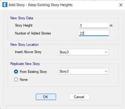
- Provide number of added stories 22 from the dialog box, click OK
- All 25 story are created then change Similar To option as Story 1
STEP5) Define Material
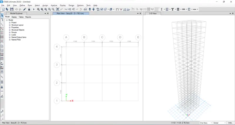
- The grid arrangement of the new modal will open
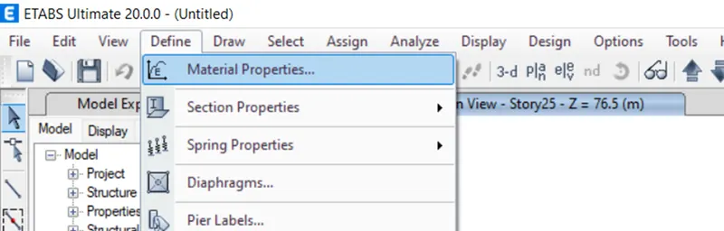
- Go to Define and click Material Property
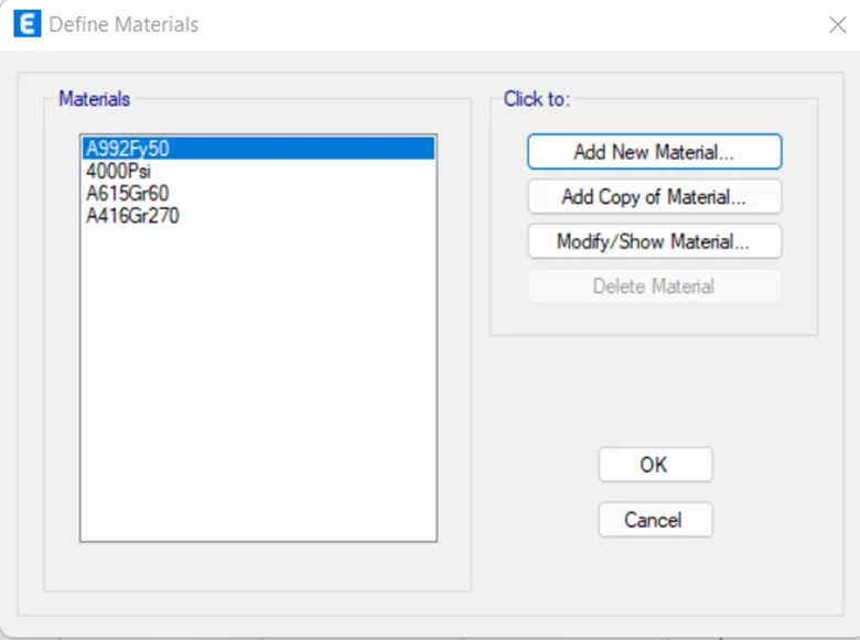
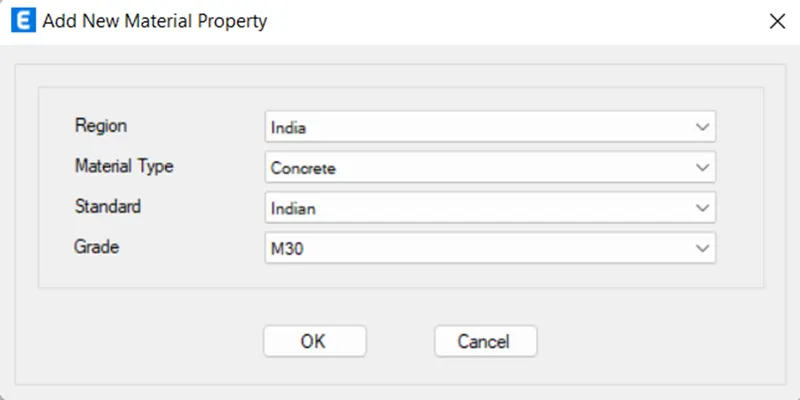
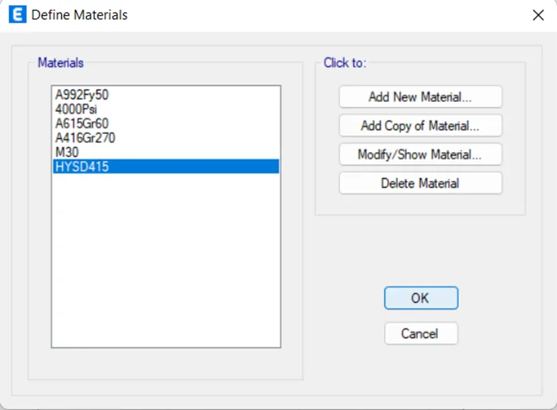
- Define Material dialog box will open, click on Add New Material
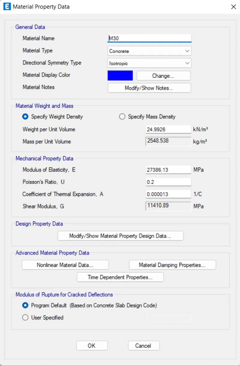
- Add New Material dialog box will open, select Material Type Concrete and ensure Grade M30 click OK
- Material Properly Data dialog box will open, click OK
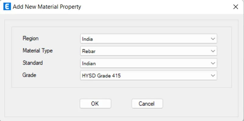
- Again, click on Add New Material
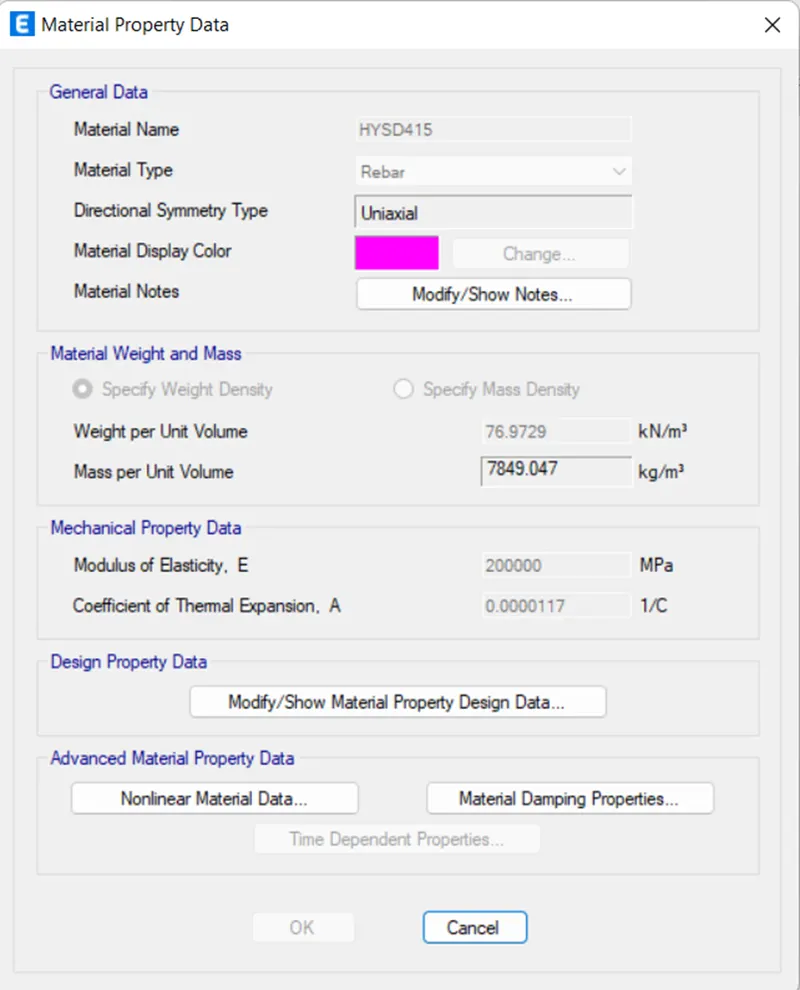
- Add New Material dialog box will open, select Material Type Rebar and select Grade HYSD 415 click OK
- Material Properly Data dialog box will open, click OK
STEP6) Add Column, Beam
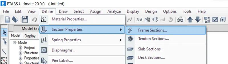
- Go to Define tab, and select Frame Section from Section Property
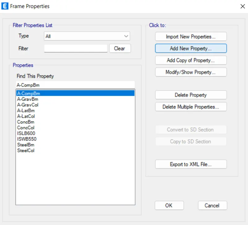
- Click on Add New Property from Frame Properties dialog box
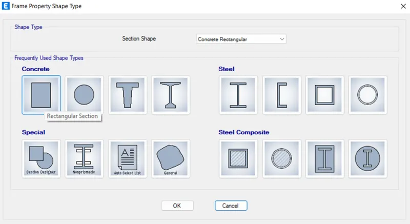
- Click on Rectangular Section for Beam from Frame Property Shape Type
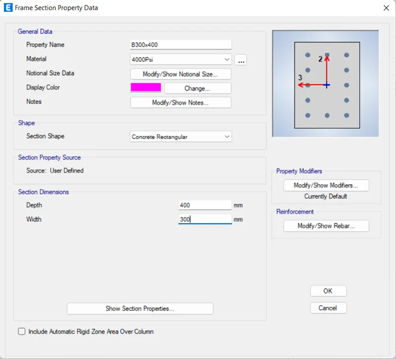
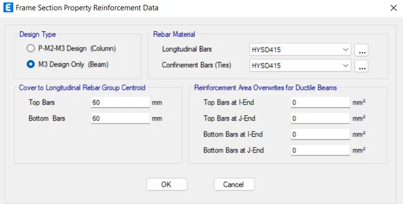
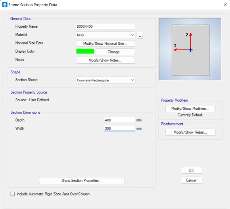
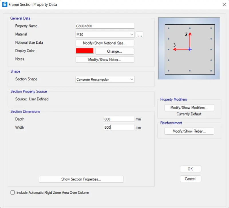
- Change the Property Name as B300X400 and Material M30 and section dimension Depth as 400 & width as 300 from Frame Section Property Data, click on Modify/Show Rebar under Reinforcement
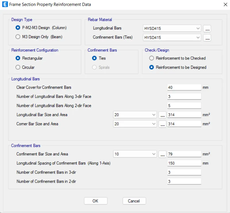
- Change Design Type and Rebar Material, click OK
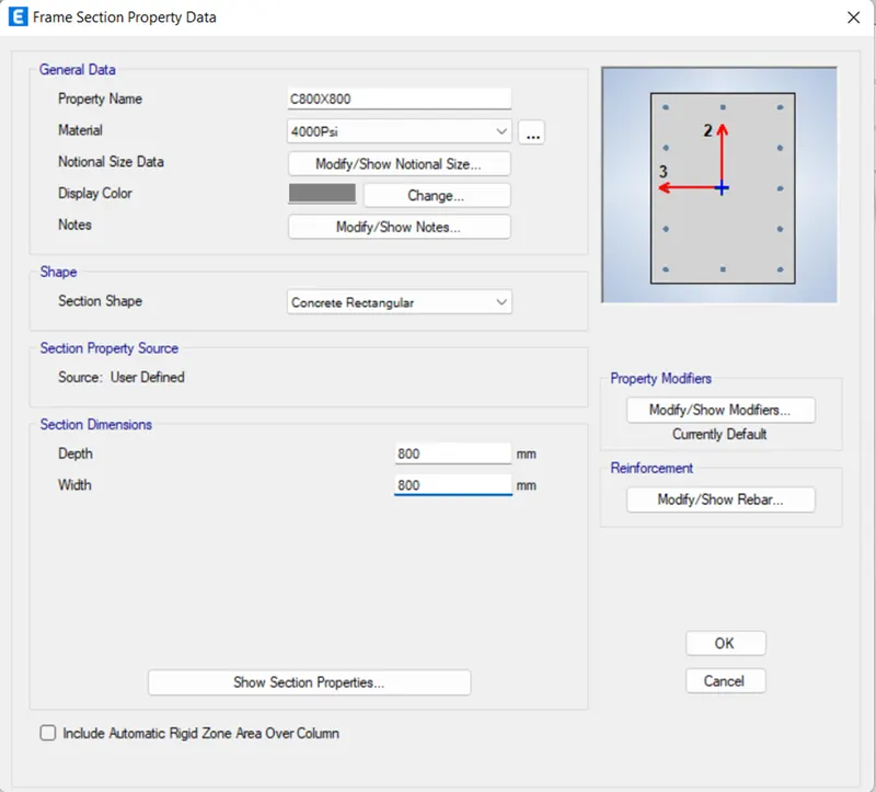
- Again, Add New Property for Column and select Rectangular Section
- Change the Property Name, Material and Dimension and Modify/Show Rebar similarly
STEP7) Add Slab
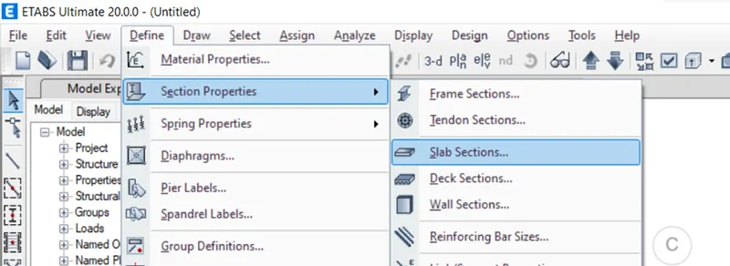
- Go to Define, Select Slab Section from Section Property
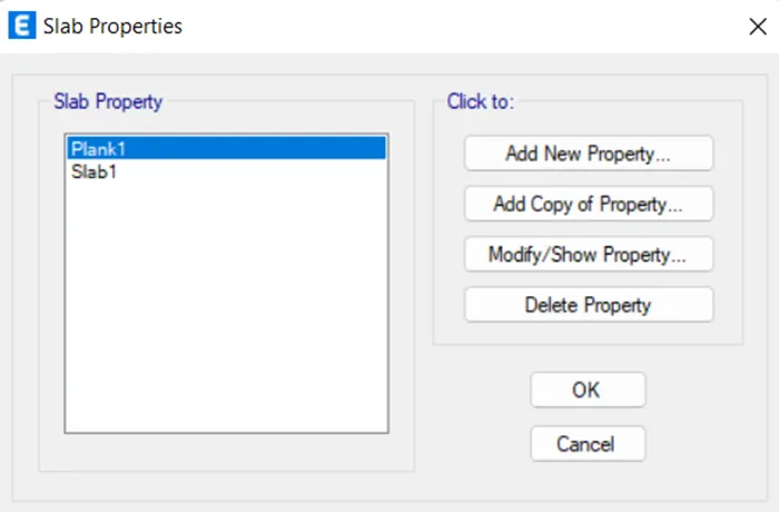
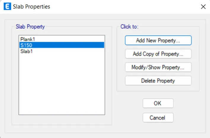
- Click on Add New Property for Slab
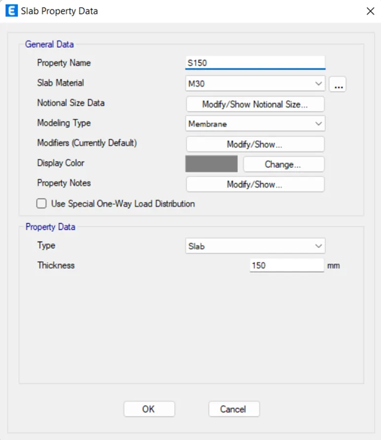
- Change the Property Name, Slab Material, Modeling Type and Thikness of Slab
STEP8) Load Pattern
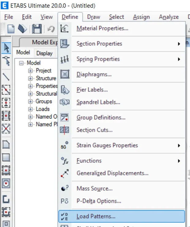
- Go to Define and select Load Patterns
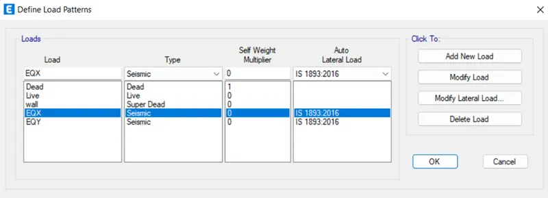
- Add Wall Load as Super Dead type
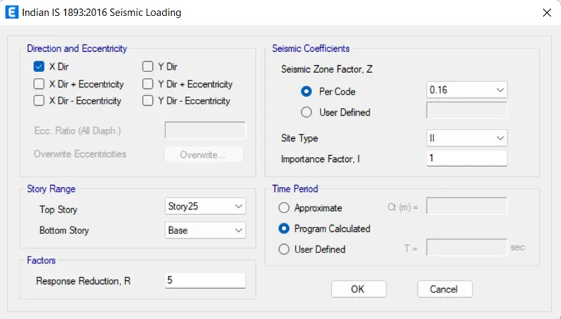
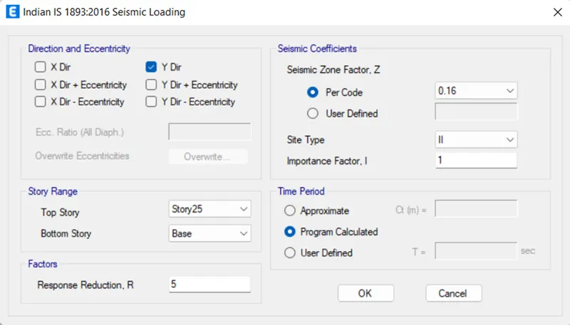
- Simalry add EQX & EQY Load as Seismic type and select IS-1893:2016
- Modify the lateral load and uncheck the other direction except X for EQX and Y for EQY
- Change the zone as per code 16
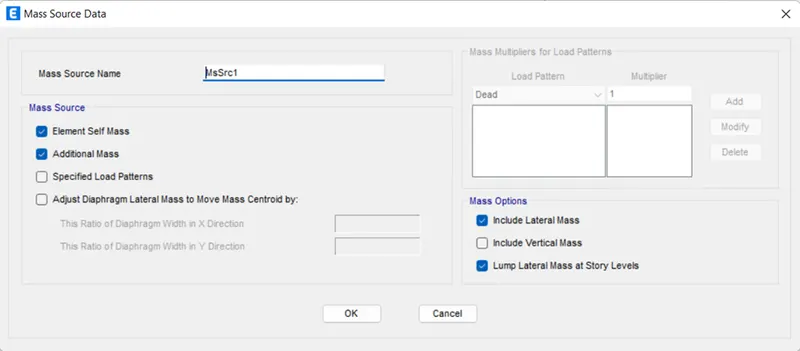
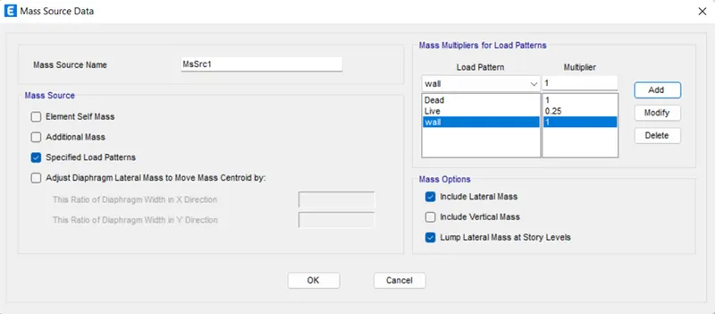
STEP9) Define Mass Source
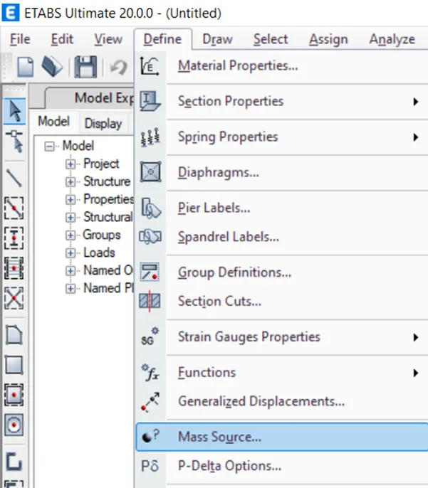
- In Define tab Select Mass Source
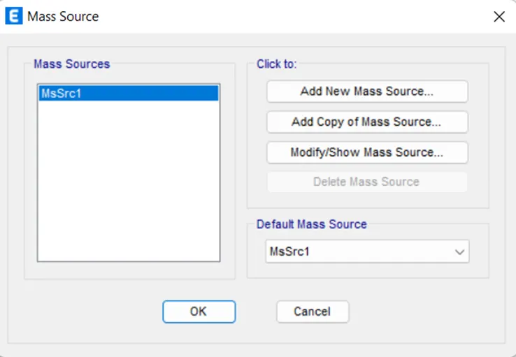
- Click on Modify/Show Mass Source
- Check mark only Specified Load Pattern
- Add wall, live and dead load
STEP10) Check Load Case
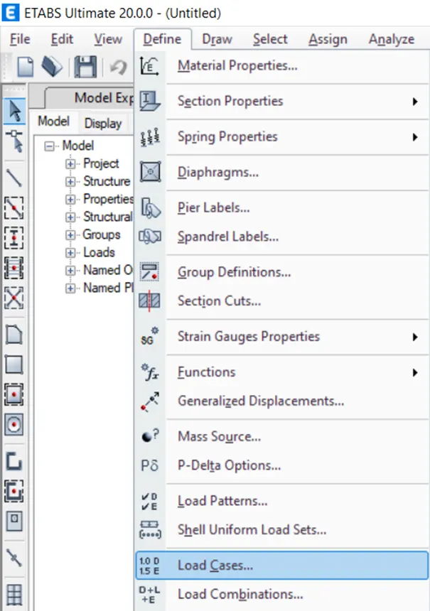
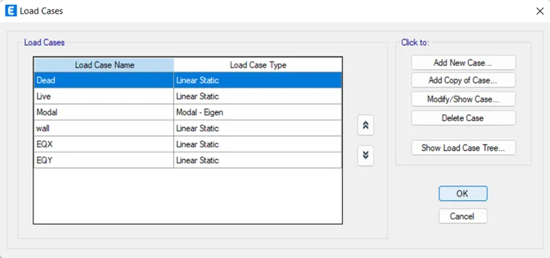
- Go to Define and select Load Cases
- Check load cases and click OK
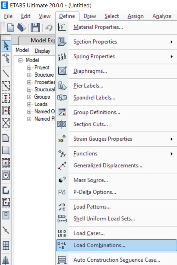
STEP11) Load Combinations
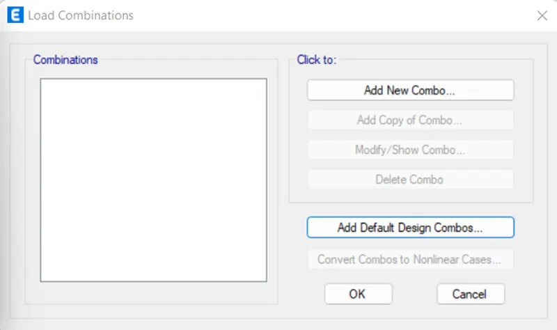
- Go to Define select Load Combinations
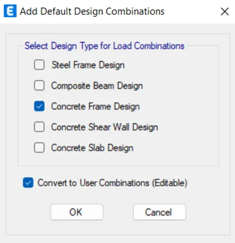
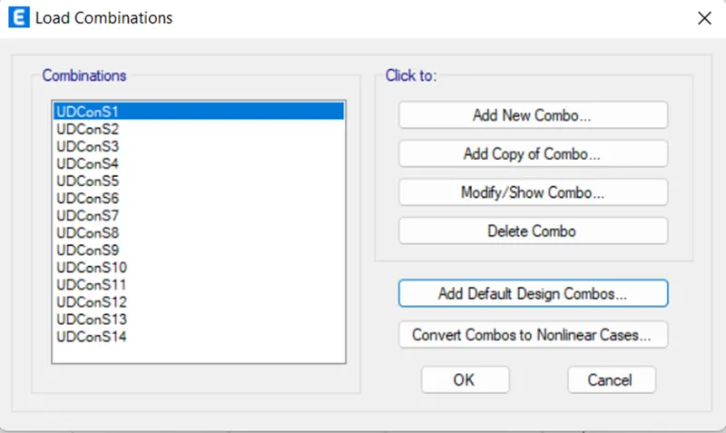
- Add Default Design Combination
- Check on Concrete Frame Design and Convert To User Combination
STEP12) Draw Column
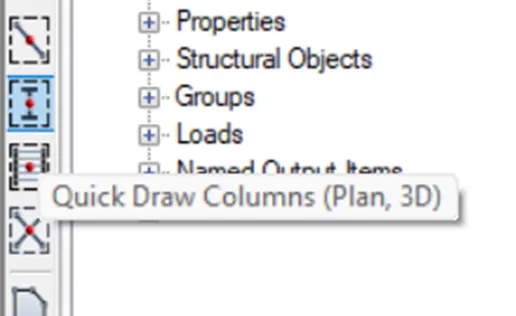
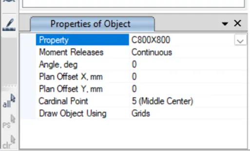
- Select Quick Draw Column
- And change the
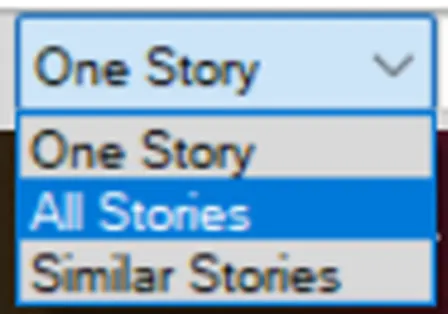
- Select All Stories
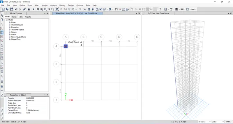
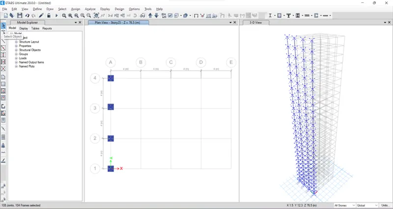
- Click on Left Most Y Direction Grid to place the column
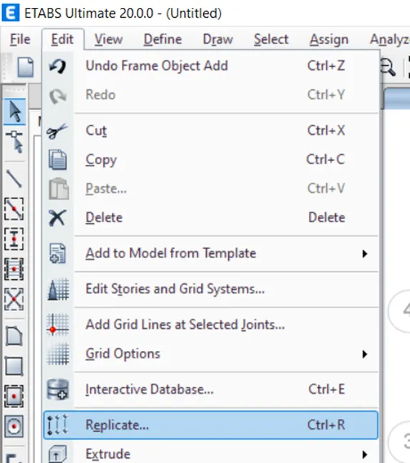
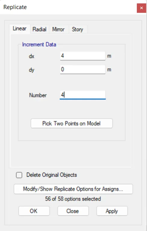
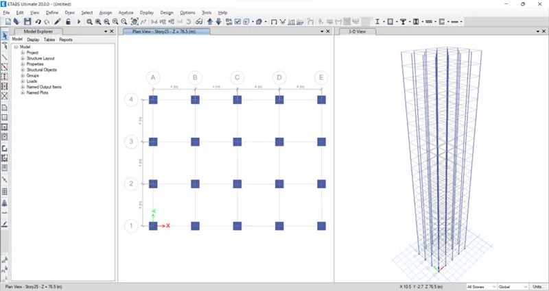
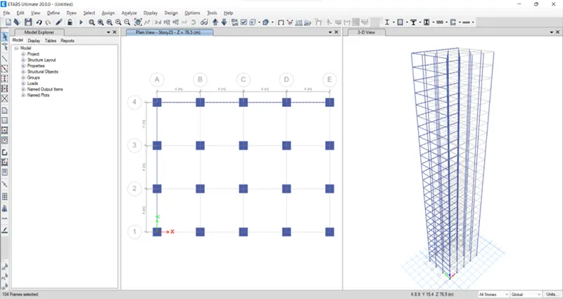
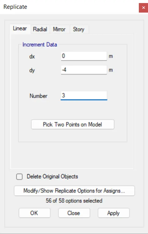
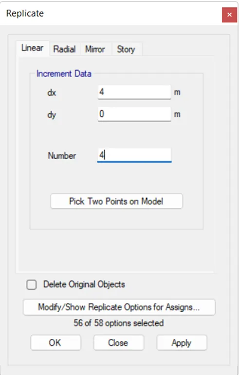
- Select all the column and make Replicate
STEP13) Draw Beam
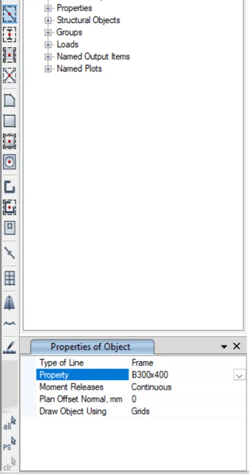
- Select Quick Draw Beam and change the Property
- Click Between Two Columns and place the beam X & Y Direction
- And make Replicate
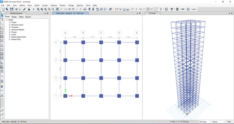
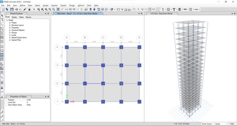
STEP14) Draw Slab
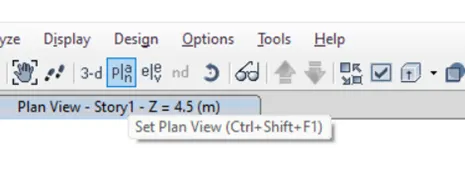
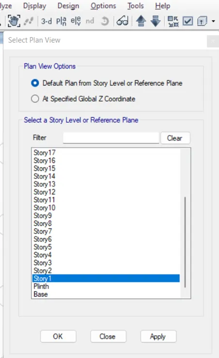
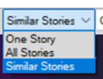
- Change set plan as Stroy 1 and Similar Stories
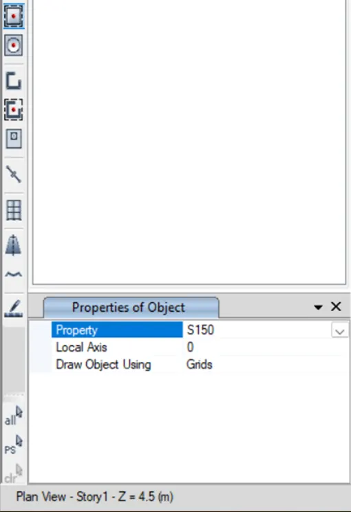
- Select Quick Draw Floor icon and change the Property
- Click on the Boundries Of The Grid
- Slab will be created for all floor
STEP15) Assign Load
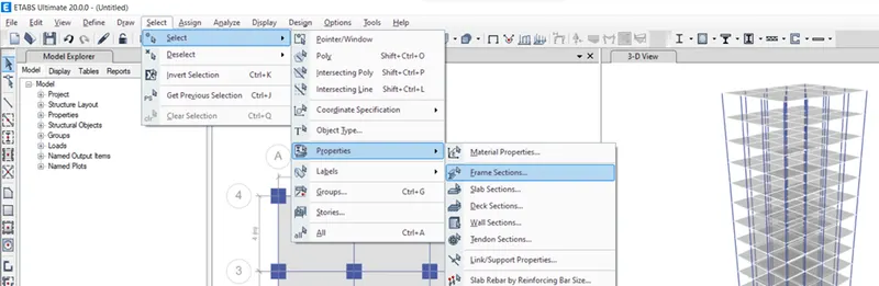
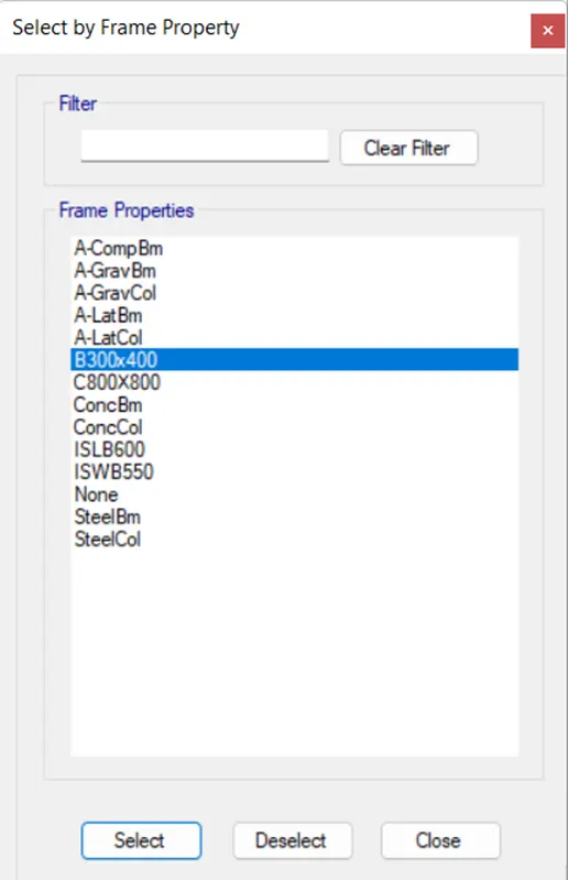
- Select all Beam
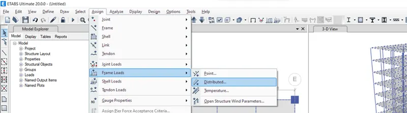
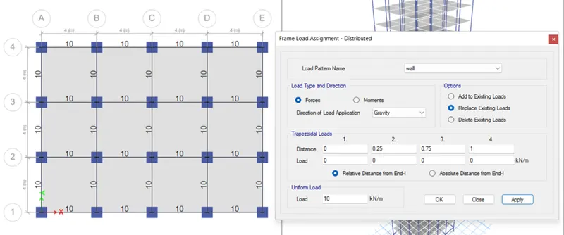
- Assign Frame Load as a Distributed
- Load Pattern Name Wall and Uniform Load 10kn/m
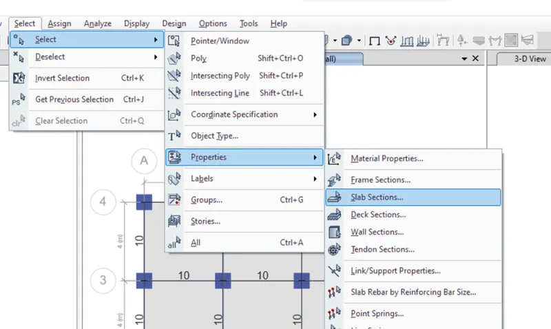
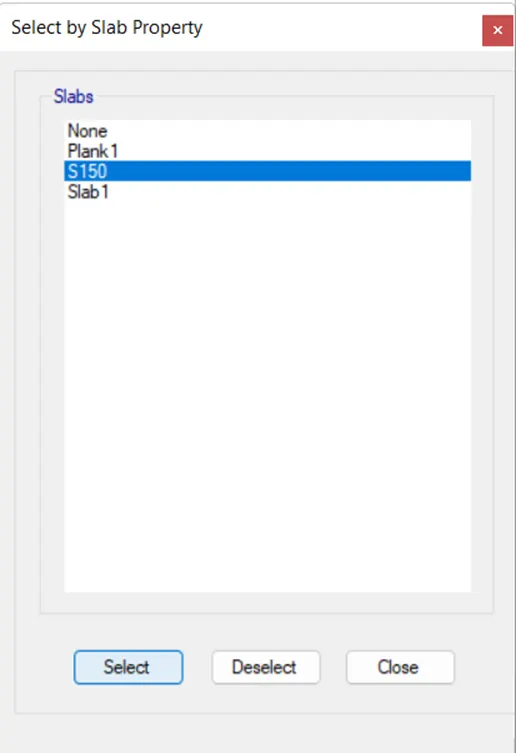
- Similarly select slab
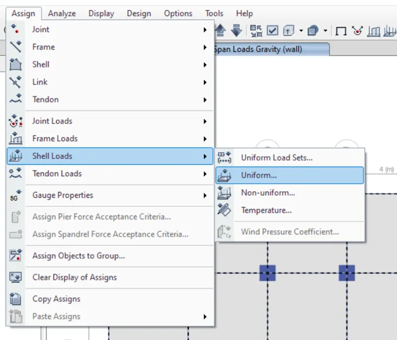
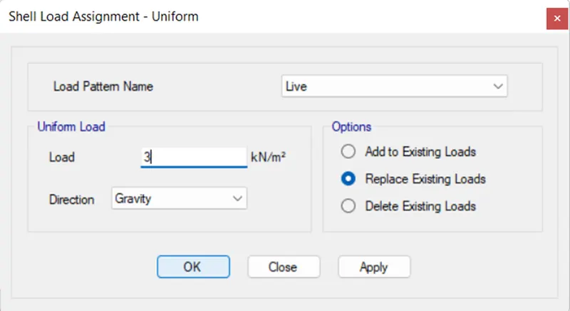
- Assign shell load as uniform
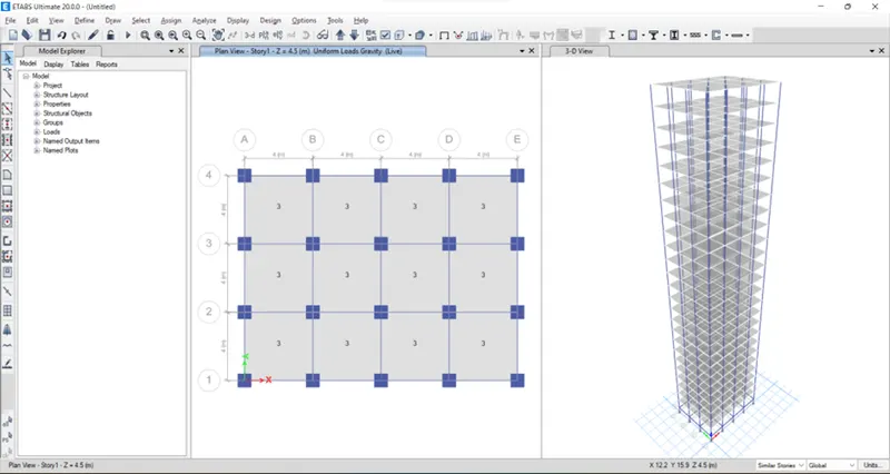
- Load Pattern Name live and Uniform Load 3 kn/m
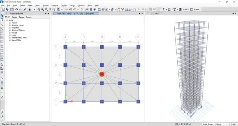
STEP 16) Add Diaphragms
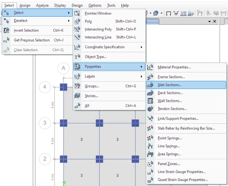
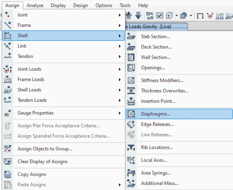
- Select Slab
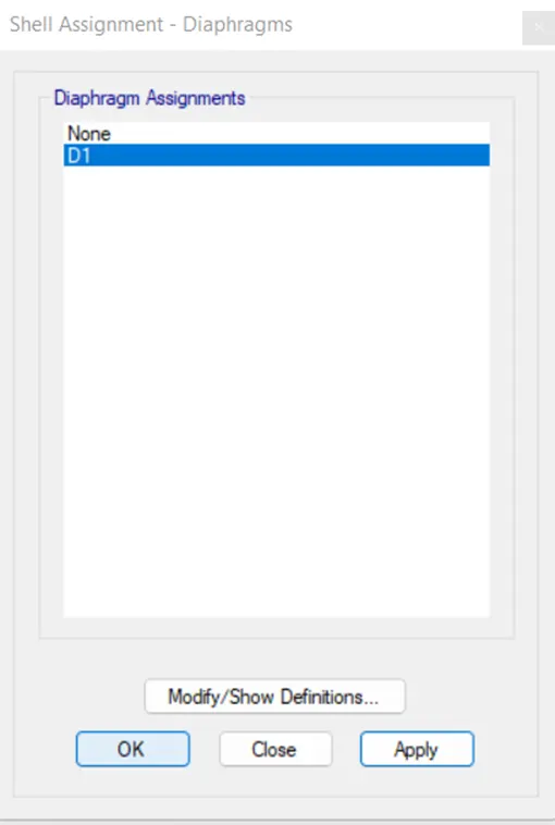
- Assign Shell as Diaphragms
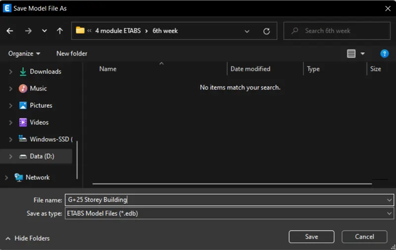
STEP 17) Save the Model
- Choose appropriate folder and name to save the model
STEP 18) Run Analyse the Model
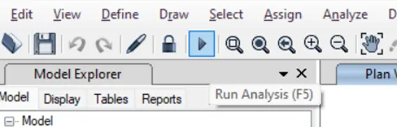
- Click on Run Analysis Button
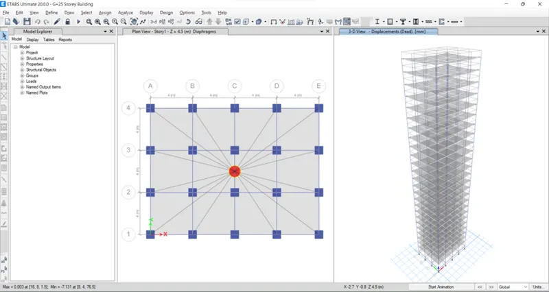
- This will Analyse the structure and provide the result
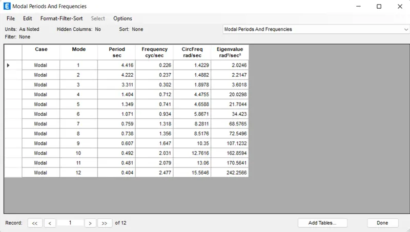
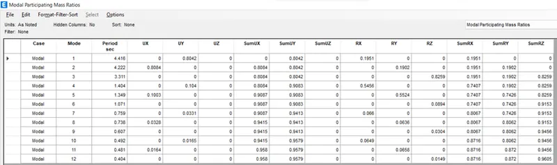
STEP 19) Check the Model Information
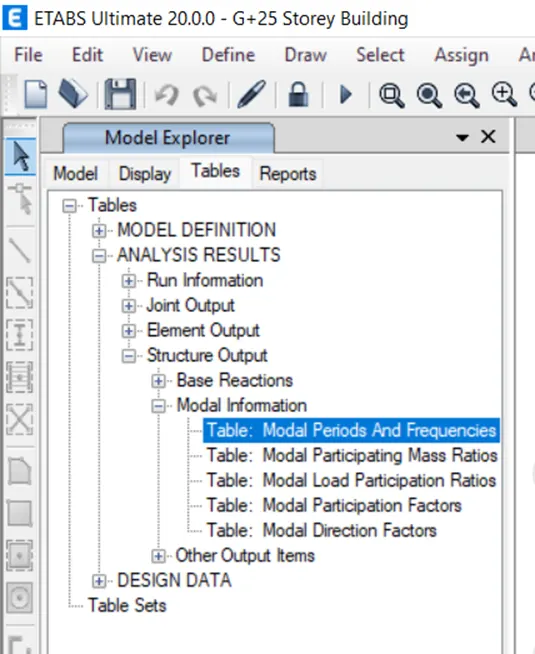
- Click on Tables in Model Explorer tab
- Goto Tables>Analysis Result>Structure Output>Model Information
- Click one by one to all table and check the results
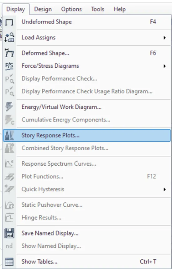
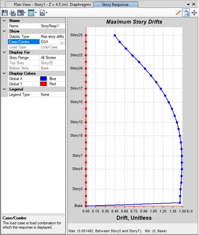
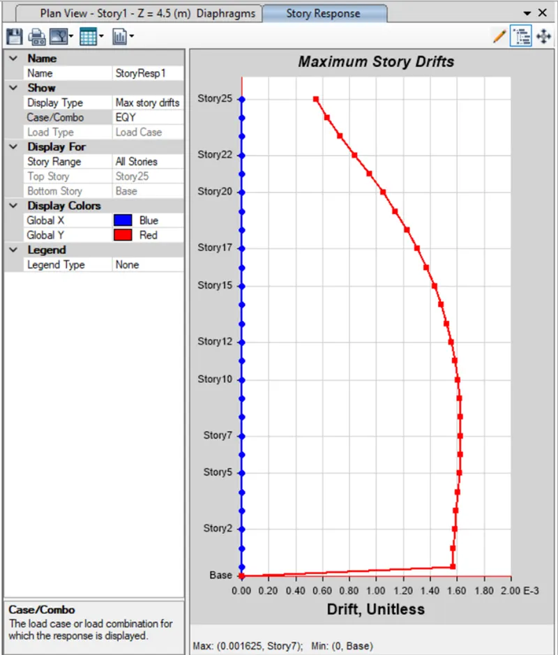
STEP 20) Plots the Story Response
- Goto open Story Response Plot from Display
- Change the Display Type and Case/combo for EQX and EQY
- Verify the Maximum Story Drifts for both EQX and EQY
RESULT:
|
Criteria |
|
Desirable Solution |
Exercise Result |
|
Fundamental Translation natural period |
X- direction |
4.4 second |
4.6 |
|
Y-direction |
4.2 second |
4.6 |
|
|
Torsional irregularity |
IS 1893-2016(Part-1) Table-5 |
Torsional mode Time period should be lesser than X and Y direction time periods |
Yes |
|
Vertical irregularity |
IS 1893-2016(Part-1) Table-6 Clause-7 |
First three modes together should contribute at least 65% in mass participation factor in each principal direction |
Yes |
|
|
Fundamental lateral natural periods in two principal plane directions are away from each other by at least 10% |
No |
|
|
Inter-storey Drift |
IS 1893-2016(Part-1) Clause-7.11.1.1 |
Storey drift shall not exceed 0.004 times storey height for base shear with no load factors (4x10⁻³) |
Yes |