Modelling of 25 storey building with the specified properties using ETABS
Aim:-
Model a 25-story building on ETABS with structural properties as specified below. Ground floor or plinth floor level can be taken at 1.5 metres from the base. Each of the next 25 stories has a story height of 3 meters.
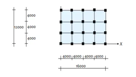
Required Details:-
structural Element Sizes
- Beams: 300 × 400 mm
- Columns: 800 × 800 mm
- Slab: 150 mm thick
Material Properties
- Grade of Concrete: M30
- Grade of Steel Reinforcement Bars: Fe 415
Loading
- Dead Load on beams from infill wall: 10 kN/m (Let us assume the same for the roof floor in view of the parapet)
- Live load on the floor : 3 kN/m2 (Let us assume the same for the roof floor)
Other Details:-
a) Buildings are assumed to be pinned at the base
b) All columns in all stories are of the same size
c) All beams in all stories are of the same size
d) Building is located on Soil type II and in Zone III. Assume other factors if required.
The translational fundamental natural period of vibration:-
In x direction 0.44 sec.
In Y direction 0.42 sec.
Procedure:-
- Open the ETABS software.
- Click the file menu and choose to create a new model option.
- After choosing a new model a dialogue box will appear as model initialization.
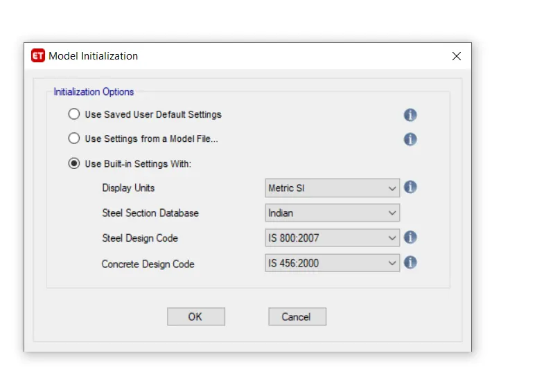
- Choose the built-in settings option and select the display units and codes.
- After model initialization selects the grid and story inputs from the New model quick templates dialogue box.
- In this dialogue choose custom grid spacing and custom story datata which is used to provide the inputs specified above.
- Enetr X grid data at a distance of 4 metreand Y grid data as 4 at a distance of 4 metre.
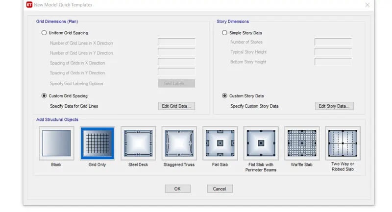
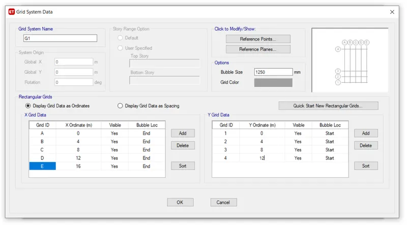
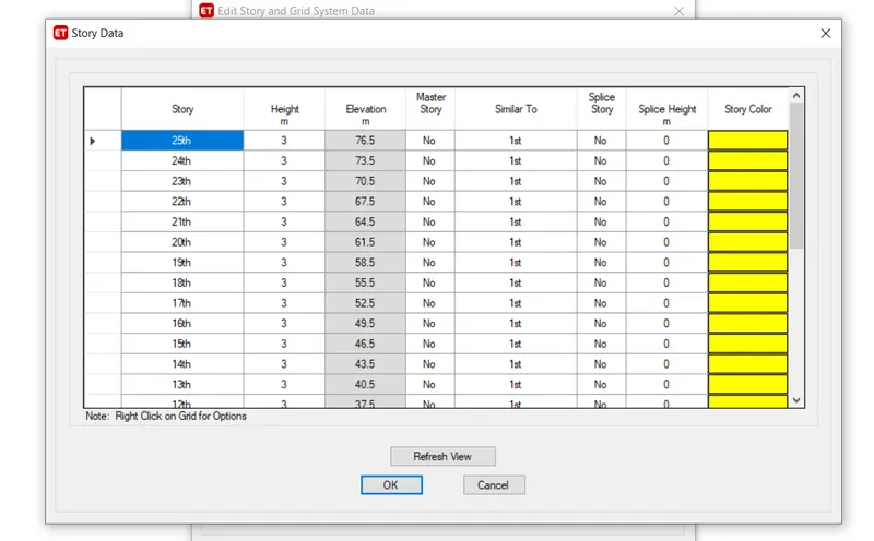
- Now edit the stories by using the user defined storey input,26 storeys are incorportaed( plinth at 1.5 meters height+ 25 stories with 3-meter height each). Storey 1 has benn labelled as master storey and all above levels are labelled similar to that.
- Select Material properties under the defined tab.
- Define the materials of concrete M30 grade and steel of transverse reinforcement as 415 grade and longitudinal reinforcement as 500 grade.
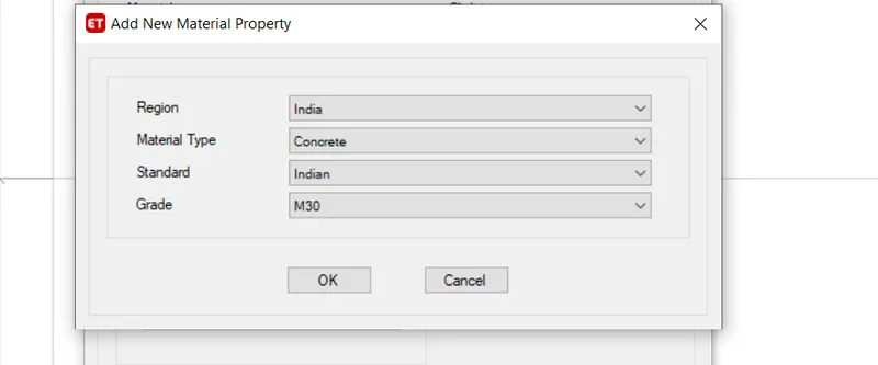
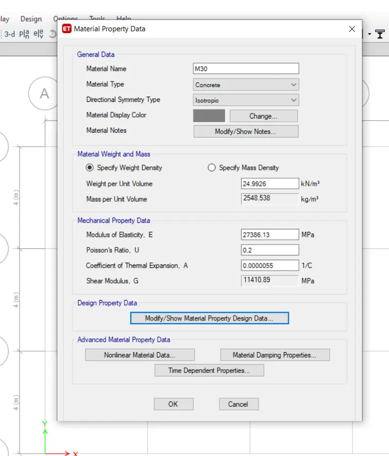
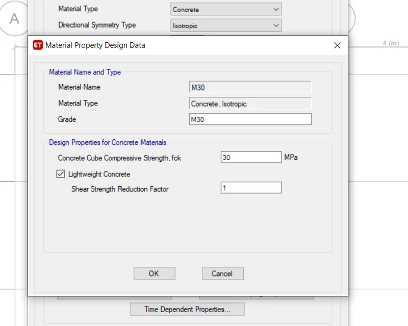
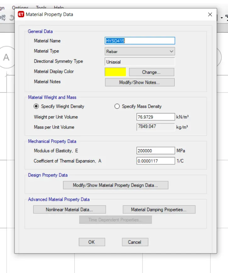
- Select Section properties under the defined tab.
- Click on the frame section and create a new property as beam and input the values as 300X400mm.
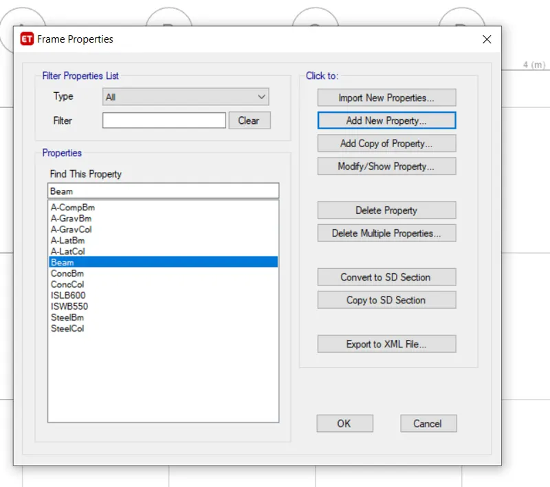
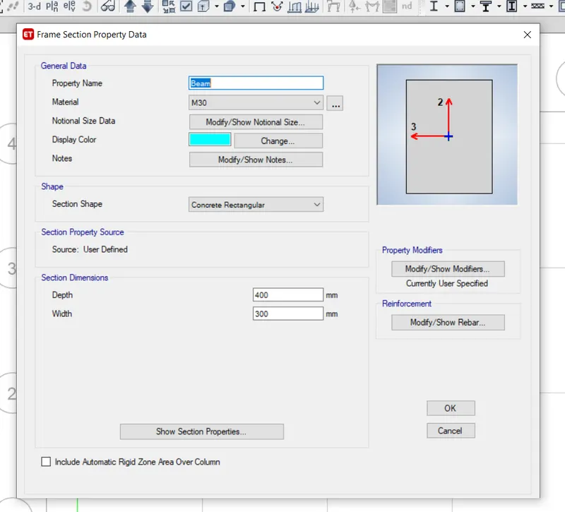
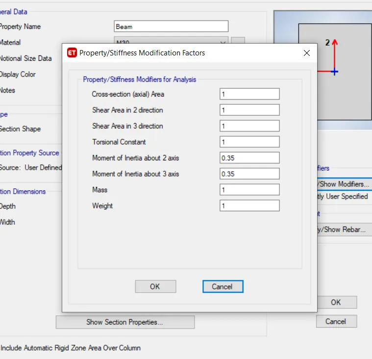
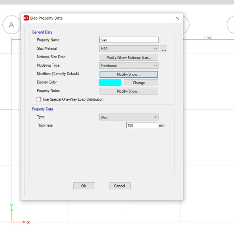
- After the defined properties for the column as 800X800 and slab thickness ass 150mm
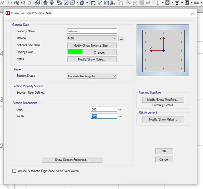
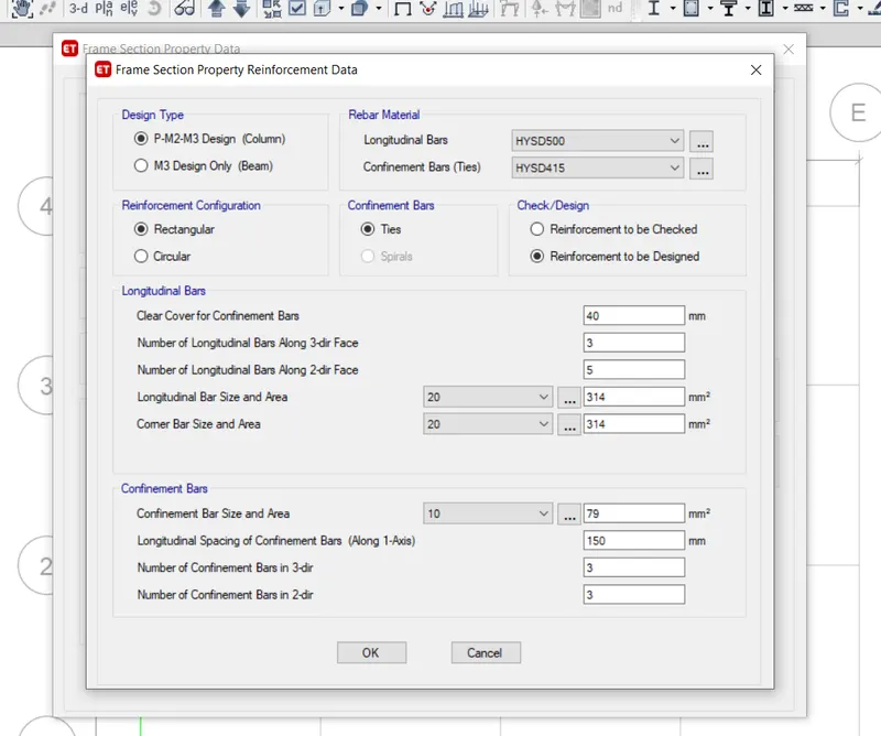
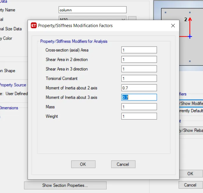
- Using the membrane property, a slab size of 150mm has been added to the list. Membrane property will help to consider only slab weights and floor weights in the analysis of structure while no stiffness component of flange advantage is considered during calculation.
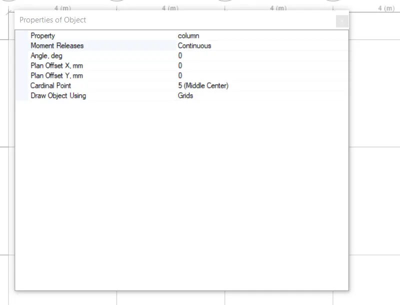
- Draw a column of size 800X800mm at the intersection of the horizontal and vertical grid and beams with quick draw tool keeping all stories on.
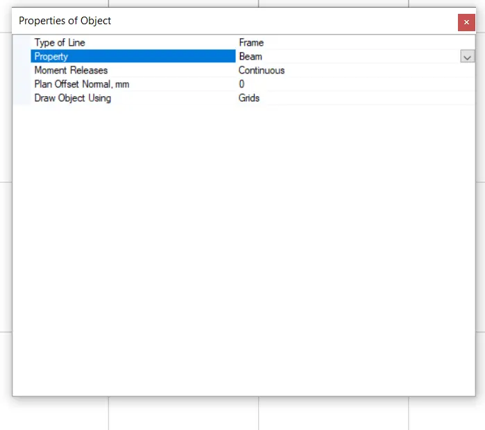
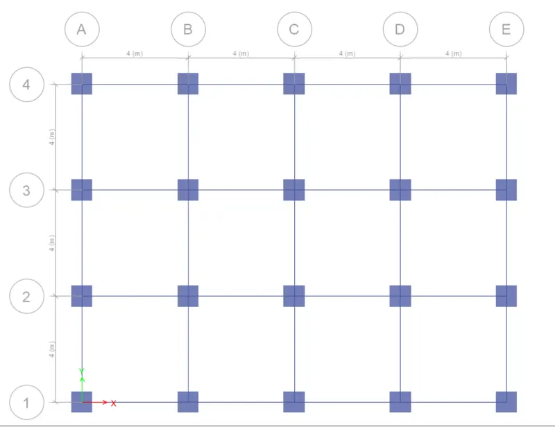
- Drawn Beams using the quick draw beam tool keeping all the stories on.
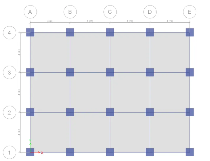
- Using the quick draw floors option, all the slabs have been modeled keeping"similar stories" ON.
- Select assign and click on joint select pinned support. Fix the pin supports at the base.
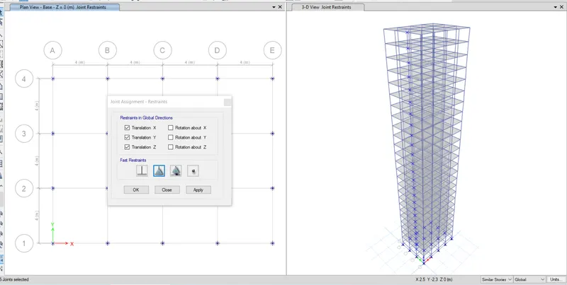
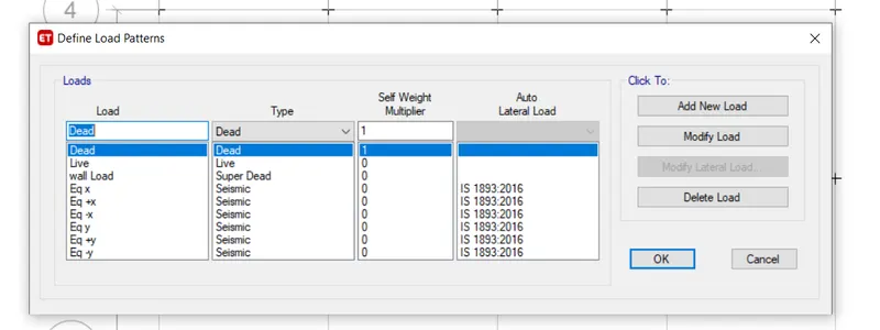
- Now define the load patterns: click on the define ta and click on load patterns.
- Define the loads like dead load, live load, brick load, and earthquake load in the x direction and positive x and negative x and the same loads in the Y direction also. Mention IS codes of respective loads.
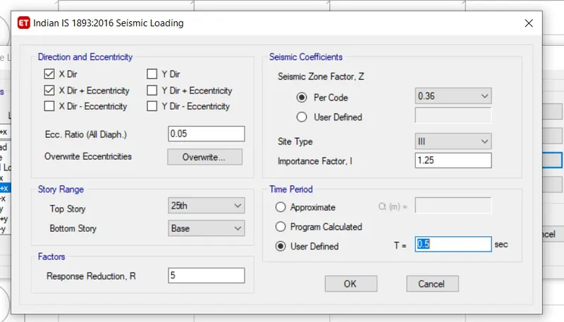
- Click on modify lateral load, set range from base to 25th storey and seismic zone factor as 0.36,importance factor 1.25 and time period 0.5 seconds.
- Do the same for all the earthquake loads. Assign the loads and select similar stories. Click on shell load under the assigned tab.Click on live load and give the value as 3kn/m^2.
- Click on apply.
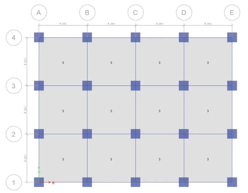
- For the roof, we will take only 50% of the live load.
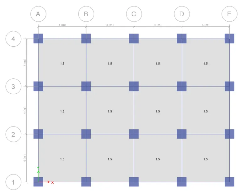
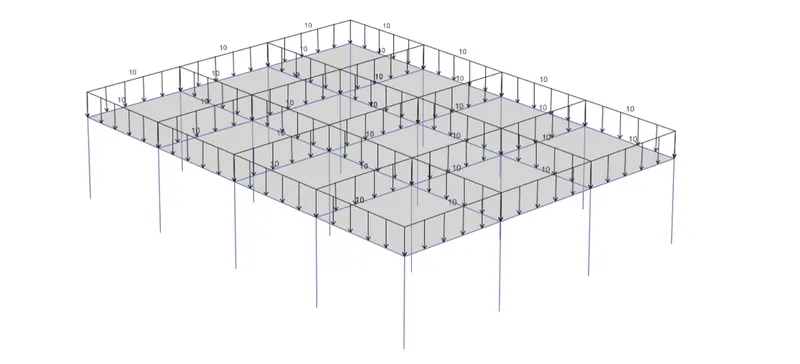
- Similarly, add a live load of 10Kn/m^2 on all the beams.
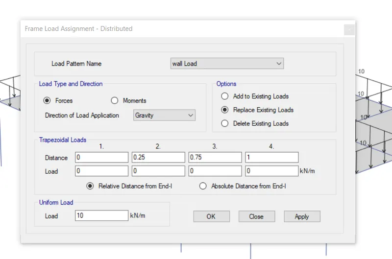
- For that select all the beams from select object type beams.
- Goto the frame load and click on the distributed load and enter the value as 10 Kn/m^2.
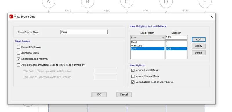
- Now go to mass source from the defined tab.
- Modify the mass source and tick mark the required loads.
- Add load patterns and assign them to the model.
- Define the load cases:
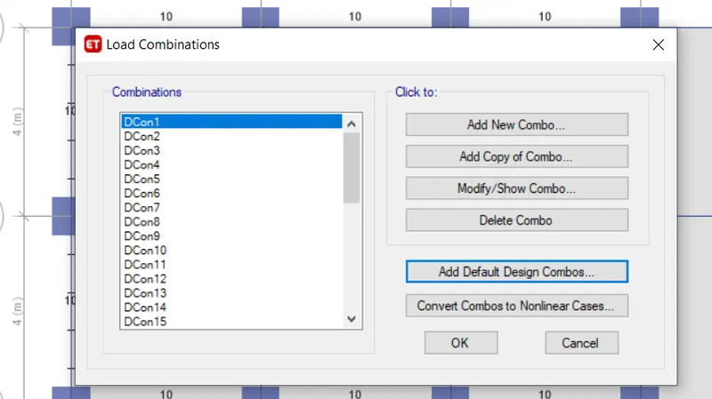
- Click on the load combinations.
- Click on the add default design combos.
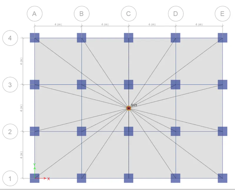
- Now create the diaphragm by going to the assigned tab then shell and select diaphragms.
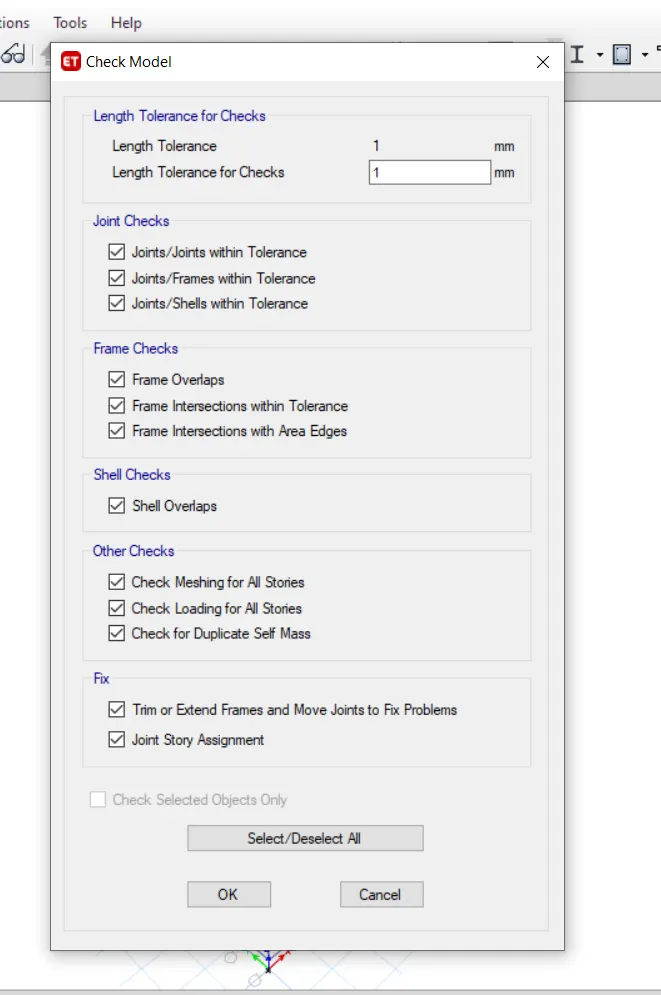
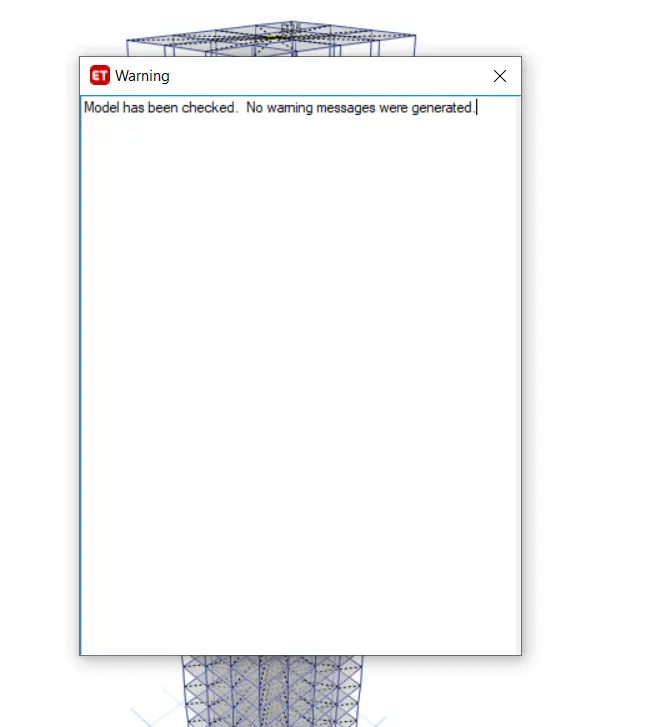
- Analyze the model using analyze option then click on the check model,the modelled strucrue is verified without errors and warnings.
- Using analyze>run analysis, the model is analyzed and deflection patterns and BMD/SFD patterns are cross-checked logically. It is understood that the worked model provides reliable results.
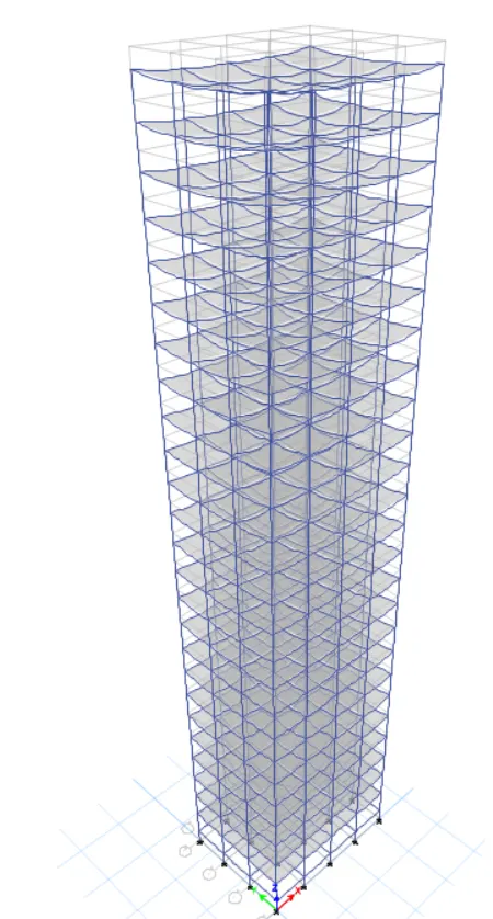
Results:
- Now click on Display>show tables>Analysis results>Structure ouput>Modal information>modal periods and frequencies.
- The time periods for fundamental mode-1Y direction and fundamental Mode -1X direction is noted in the table and is as follows:
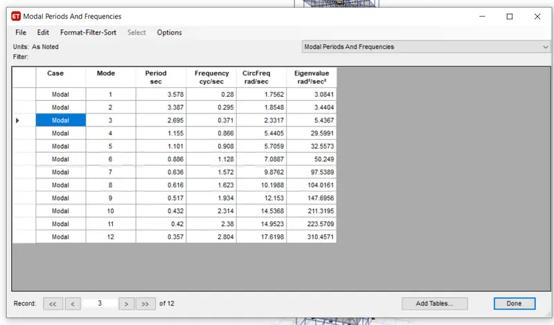
- Tx1=3.578 seconds and Ty1=3.387 seconds
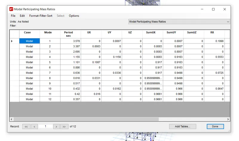
- Display>show tables>analysis results>structure output>modal information>modal participation mass ratios.
- From the table the natural time period for mode-1 and torsional DOF are noted as follows:
- Tx1=3.578 seconds Ty1=3.387 seconds Txy1=2.695 seconds
- So from the results, it is clear that the torsional time period is less than two translational time periods as required by IS 1893 provision table 5.
- When we add the three mode mass ratios we get 0.9044 which means the first three modes of seismic oscillation contribute more than 65% of building weight as per ETABS analysis.
- The story drift for the serviceability Base shear case(EQX or EQY) is tabulated from the following tool path.
- Go to display>Storey response plot
- Keeping the load case to EQY and switching to max story drift the maximum drift value noted is 0.0030.
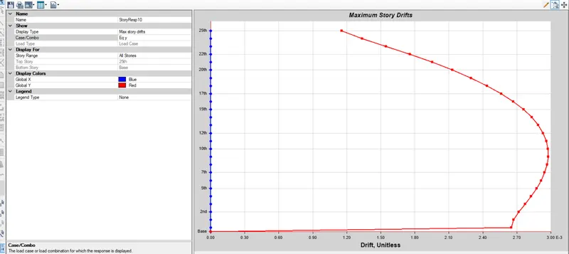
- So as per clause 7.11.1.1, the maximum inter-storey drift militates to 0.004 for each story height. But our value is 0.0030 which is within the code limits.
- Conclusion: the modeling is completed and analyzed in etabs.The results are within the given ranges.