Modelling of 25 storey building with the specified properties using ETABS
Model a 25 storey building on ETABS with structural properties as specified below. Ground floor or plinth floor level can be taken at a height of 1.5 metres from the base. Each of the successive 25 storeys has a storey height of 3 metres.
Structural Element Sizes
- Beams : 300 × 400 mm
- Columns : 800 × 800 mm
- Slab : 150 mm thick
Material Properties
- Grade of Concrete : M30
- Grade of Steel Reinforcement Bars : Fe 415
Loading
- Dead Load on beams from infill wall : 10 kN/m (Let us assume the same for roof floor in view of parapet)
- Live load on floor : 3 kN/m2 (Let us assume the same for roof floor)
objective:
- To know modelling of a high rise building in ETABS software
- To verify the seismic code requirements from ETABS analysis.
Aim:
- To model a 25 storey building on ETABS 2018 with the specified structural properties.
- To carry out the following exercises:
- Check if the translational fundamental natural period of vibration in both the x and y direction is approximately the following:
Tx1 = 2.98s
Ty1 = 3.14s
Check if the following provision in Table 5 of IS 1893 (part 1) – 2016, on torsional irregularity satisfied: - The natural period corresponding to the torsional mode of oscillation must be less than the two fundamental translational modes of oscillation along each principal plan directions.
- Check if the two provisions of clause 7 in Table 6 of IS 1893 (part 1) – 2016, regarding vertical irregularity is satisfied
- Check if provision on inter-storey drift limitations in clause 7.11.1.1 satisfied.
procedure:
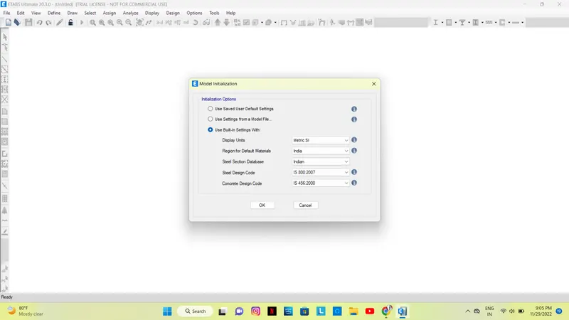
- open the ETABS software and make a new model and provide display units to metric SI, steel section in indian.
- steel design code to IS 800:2007
- concrete desing load to IS 456:2000
.
- then select custom grid spacing edit grid according to our challenge
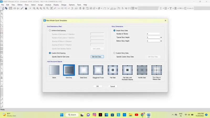
- edit custom story data set plinth level and set 25 story according to our challenge and set height to 3metre
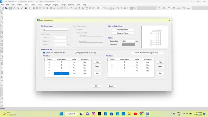
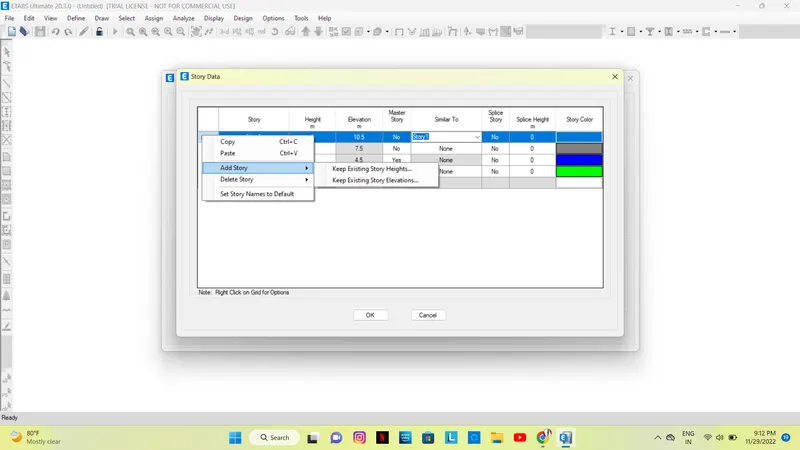
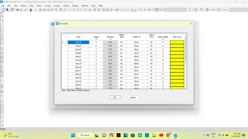
- after story setting for challenge go for defintion to the material properties, select new material properties and the set properties according to our challenge
- set concrete property to M30 grade of concrete and
- steel rebars at fe 415 (Hysd 415)
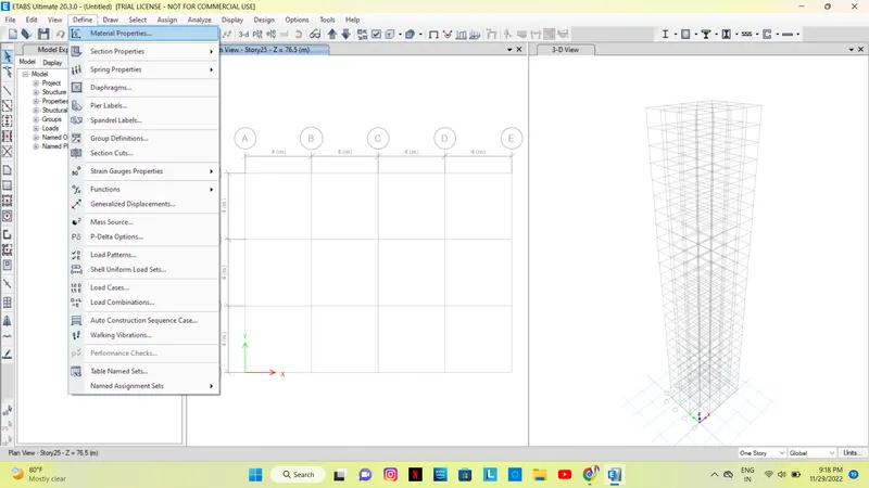
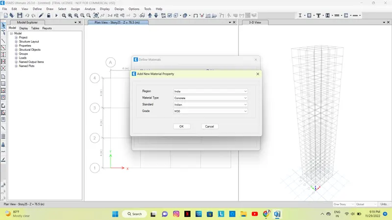
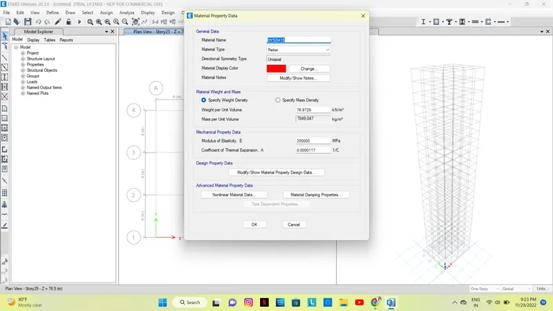
- add property frame section according to challenge
- set column 800 x 800mm
- beam 300 x 400
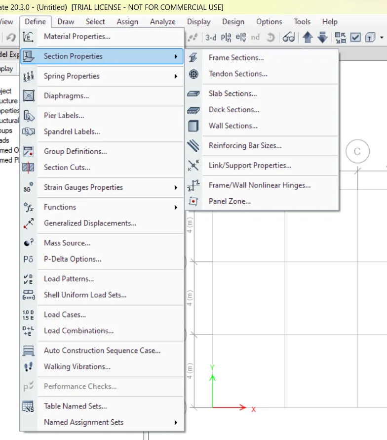
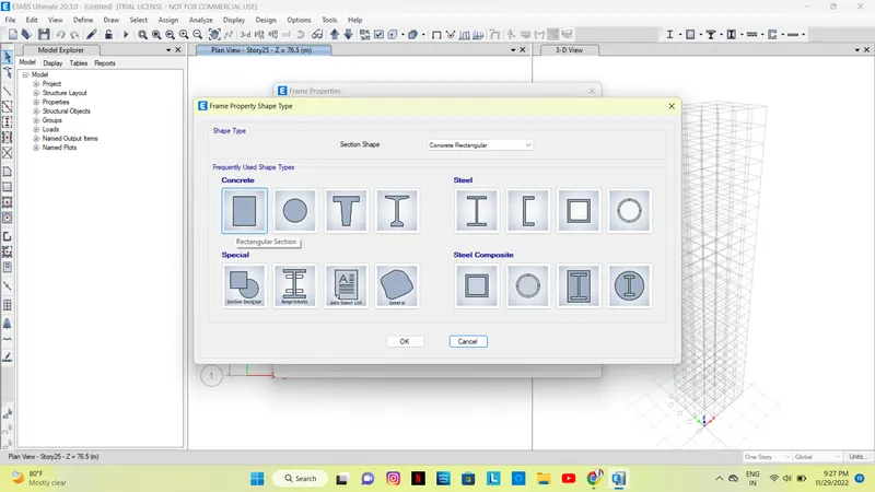
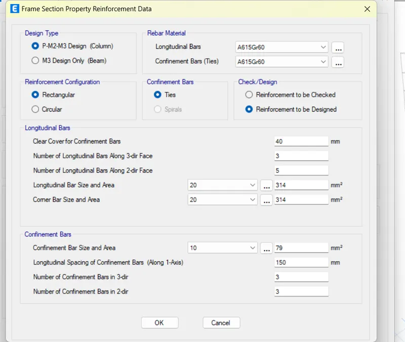
- stiffness modification factors are only applicable for ultimate load design for now we only giving to assume thr story of building .
- then set slab property of the slab at thickness of 150mm and slab property as membrane to avoid flange.
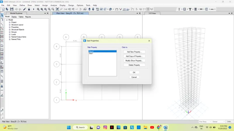
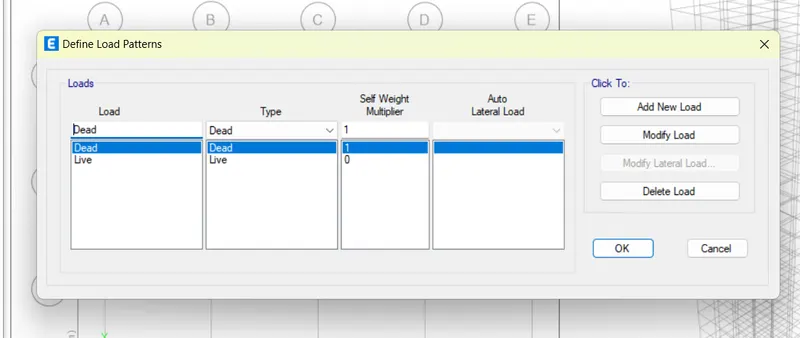
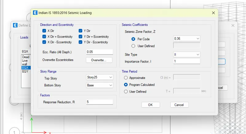
- then go for load patters dead and live load are already there , then we create wall to super dead load type and create EQX and EQY and set type of soil II keep it as program calculated
- response reduction is 5
- importance factors as 1
- how much mass should be considered for seismic lateral moment is what we going to assain
- 100% of dead load
- 25% of live load
- 100% of super dead load as IS code
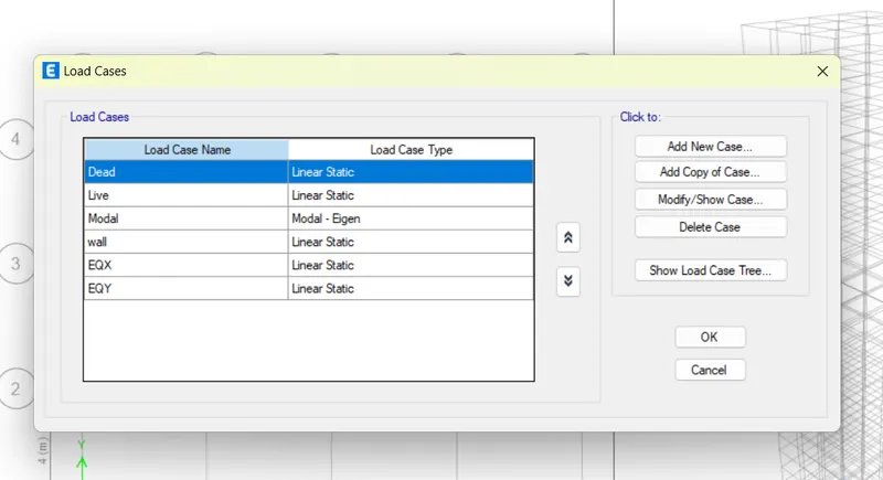
- and check for load cases for all the cases we assign is there or not
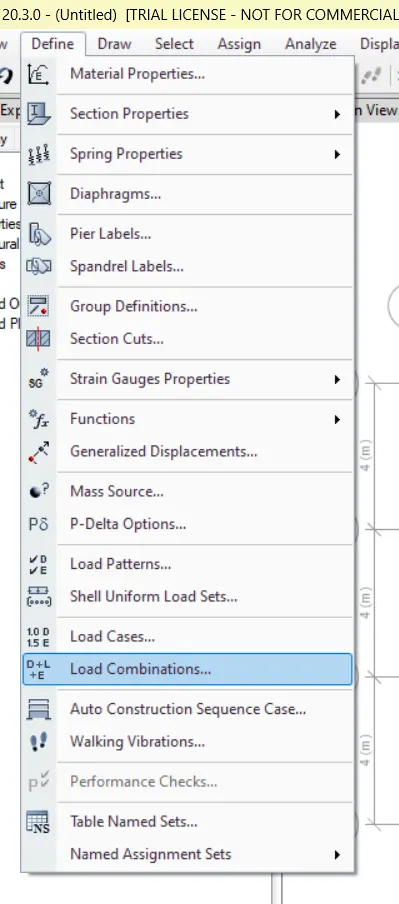
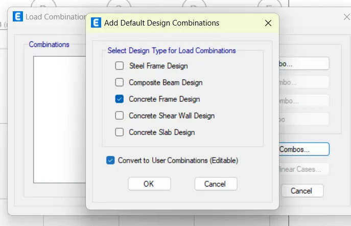
- then go for load combination for the concrete frames with user define combinations.
- now its ready for modelling stage
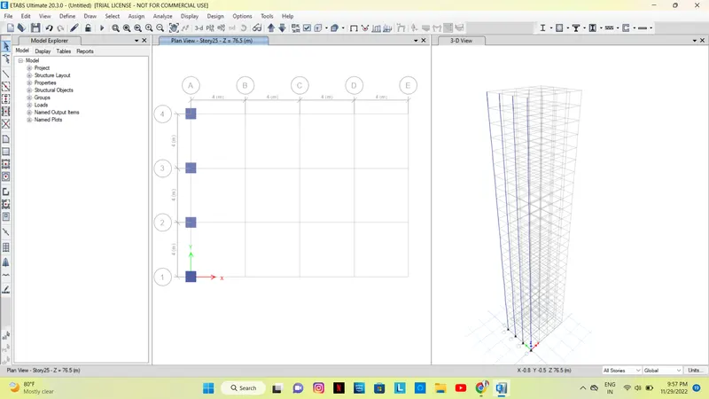
- go for quick draw collumn and choose the created property for beam and column
- and select the position of cloumn of the centre of point and replicate according to its position
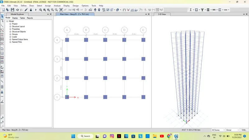
- and also the same command is used for selecting the beam according to its postion and replicate it also its position
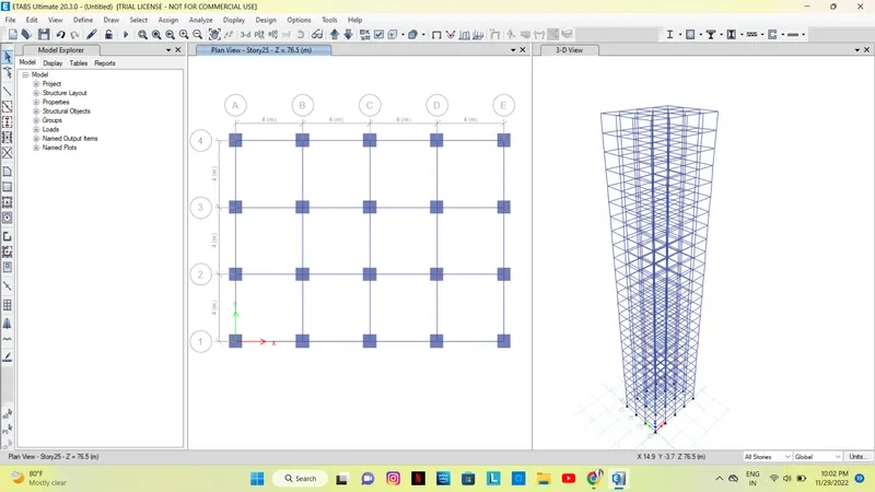
- select the property in slab
- for selecting slab we have to go for story 1 because it is master story and set all other storys are similar to story 1 except plinth level
- and go for slab property and select on the grid to place slab
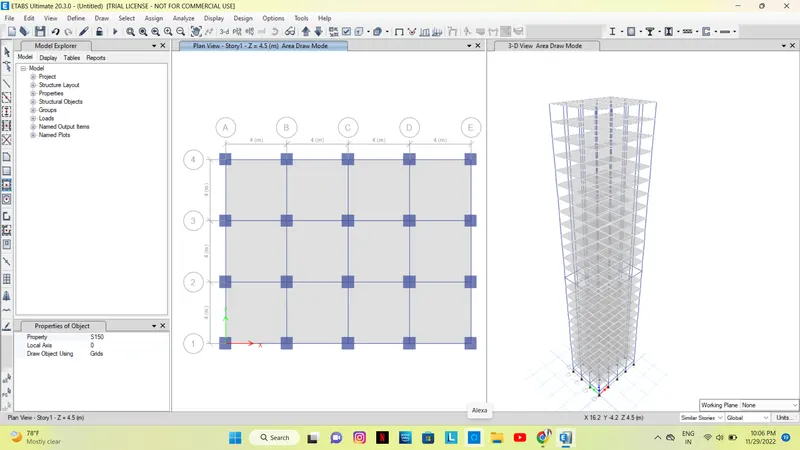
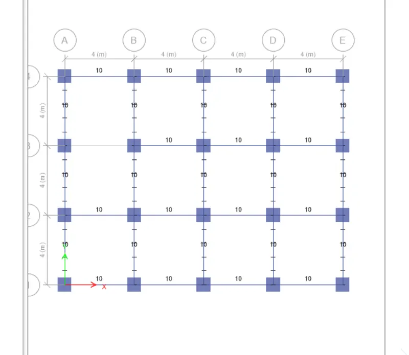
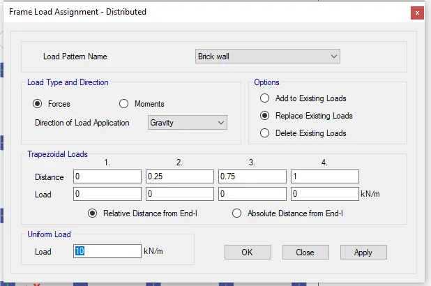
- set the load of beam 10kN/M
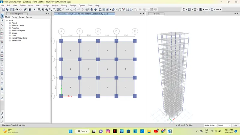
- Select all the floors. Select to Select to object type to Floors. Hence all the floors are selected.
- Then go to assign to Shell loads to uniform to Live loads to 3kN/`m^2` to apply and ok.
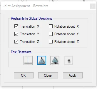
- We have to keep the support as pinned, so for this select all joints by keeping in view the base storey.
- Then Go to assign to joint to restraint to select pinned joint.
- No, go to analyse tab to check model to it is checked for any errors and warnings.
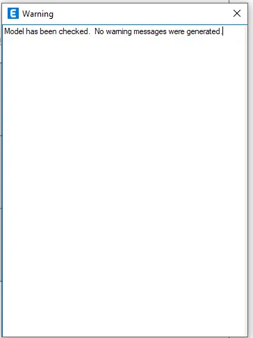
- Now, the model can be analysed. For this, go to analysis to Run analysis.
- Hence, analysis has been completed.
- Now, we need to check the details given in the question.
- So, for this initially go to display tab to Show tables to Analysis result to Structure output to Modal information to Modal periods and frequencies.
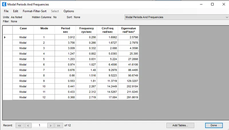
- Check if the translational fundamental natural period of vibration in both the x and y direction is as given in the question:
-
1st mode corresponds to translation in y direction, hence Ty1 = 3.912 s
-
2nd mode corresponds to translation in x direction , hence Tx1 = 3.756 s
-
- Check if the following provision in Table 5 of IS 1893 (part 1) – 2016, on torsional irregularity satisfied:The natural period corresponding to the torsional mode of oscillation must be less than the two fundamental translational modes of oscillation along each principal plan directions.
- The natural period corresponding to two translational modes of oscillation is obtained as:
- Tx1 = 3.756 s
- Ty1 = 3.912 s
- The natural period corresponding to the torsional mode of oscillation is obtained as:
-
Txy1 = 3.009
-
- Hence, it is verified that the natural period corresponding to the torsional mode of oscillation is less than the natural period corresponding to two translational modes of oscillation.
- The natural period corresponding to two translational modes of oscillation is obtained as:
- Now, modal participation ratios have to be taken, for this go to display tab --> Show tables --> Analysis result --> Structure output --> Modal information --> Modal participating mass ratios.
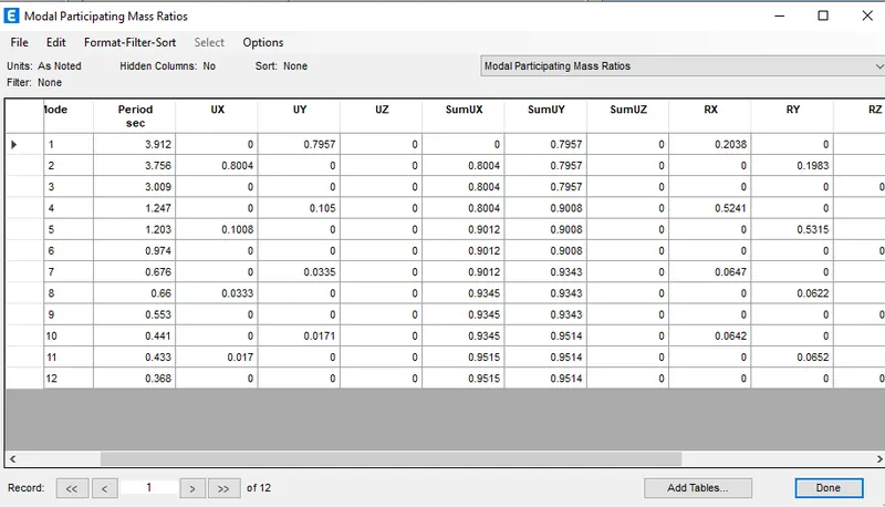
- Check if the two provisions of clause 7 in Table 6 (shown below) of IS 1893 (part 1) – 2016, regarding vertical irregularity is satisfied.
- Modal mass participation ratios of first three modes in X direction is obtained as obtained are:
-
- 1st = 0.2038
- 2nd = 0.8004
- 3rd = 0
- Summing these three we get, 0.8004+0.2036+0 = 1.004 `~~`100% > 65% . Hence it satisfies the criteria i.e, the first three modes together contributes atleast 65% mass participation factor in each principal plan direction.
- Now, the difference between X and Y time period is given by, 3.912-3.756 = 0.156 `~~`3.98%. Hence, it does not satisfy the criteria of the code i.e the fundamental natural periods of the two buildings in the two principal plan directions are away from each other by at least 10% of the larger value.
- Check if provision on inter-storey drift limitations in clause 7.11.1.1 satisfied. Please note that this check is for Serviceability Limit State and hence is for situation when structure is subjected to unfactored seismic base shear
- For obtaining the story drift graph go to display --> Story response plots --> Change the display type to Max. story drift --> load case combo - Eqx.
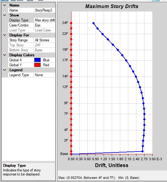
- Here, the maximum storey drift obtained is 0.0027 which is less than 0.004, hence codal provision is satisfied.
Result:
The analysis of the 25 storey building is completed and the specified checks were also carried out. The structure satisfies all the codal provision except the second provisions of clause 7 in Table 6 of IS 1893 (part 1) – 2016, regarding vertical irregularity, which is given as the fundamental natural periods of the two buildings in the two principal plan directions are away from each other by at least 10% of the larger value.