Modelling of 25 storey building with the specified properties using ETABS
Question: - Model a 25-storey building on ETABS with structural properties as specified below. Ground floor or plinth floor level can be taken at a height of 1.5 metres from the base. Each of the successive 25 storeys has a storey height of 3 metres.
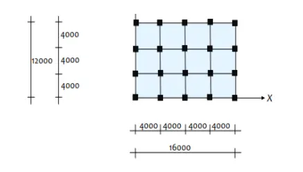
Structural Element Sizes
- Beams: 300 × 400 mm
- Columns: 800 × 800 mm
- Slab: 150 mm thick
Material Properties
- Grade of Concrete: M30
- Grade of Steel Reinforcement Bars: Fe 415
Loading
- Dead Load on beams from infill wall: 10 kN/m2 (Let us assume the same for roof floor in view of parapet)
- Live load on floor: 3 kN/m2 (Let us assume the same for roof floor)
a) Buildings are assumed to be pinned at the base
b) All columns in all storey are of the same size
c) All beams in all storeys are of the same size
d) Building is located on Soil type-II and in Zone-III. Assume other factors if required.
Carry out the following exercises:
- Check if the translational fundamental natural period of vibration in both the x and y direction is approximately: Tx1">Tx1Tx1= 4.4 second Ty1">Ty1Ty1= 4.2 second
This check will help confirm if modelling is done correctly. Some deviations from the above values are possible (± 2%). But any major deviation will suggest an error in modelling.
- Check if the following provision in Table 5 of IS 1893 (part 1) – 2016, on torsional irregularity satisfied:
The natural period corresponding to the torsional mode of oscillation must be less than the two fundamental translational modes of oscillation along each principal plan directions.
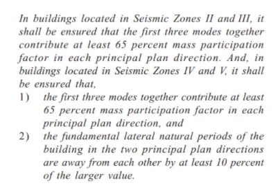
- Check if the two provisions of clause 7 in Table 6 (shown below) of IS 1893 (part 1) – 2016, regarding vertical irregularity is satisfied
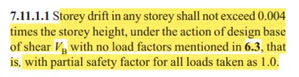
- Check if provision on inter-storey drift limitations in clause 7.11.1.1 satisfied. Please note that this check is for Serviceability Limit State and hence is for situation when structure is subjected to unfactored seismic base shear
AIM: -
(a) To model a 25-storey building on ETABS with structural properties. Ground floor or plinth floor level can be taken at a height of 1.5 metres from the base. Each of the successive 25 storeys has a storey height of 3 metres.
Structural Element Sizes
- Beams: 300 × 400 mm
- Columns: 800 × 800 mm
- Slab: 150 mm thick
Material Properties
- Grade of Concrete: M30
- Grade of Steel Reinforcement Bars: Fe 415
Loading
- Dead Load on beams from infill wall: 10 kN/m2 (Let us assume the same for roof floor in view of parapet)
- Live load on floor: 3 kN/m2 (Let us assume the same for roof floor)
- a) Buildings are assumed to be pinned at the base
- b) All columns in all storey are of the same size
- c) All beams in all storeys are of the same size
- d) Building is located on Soil type-II and in Zone-III. Assume other factors if required.
(b) Carry out the following exercises:
- Check if the translational fundamental natural period of vibration in both the x and y direction is approximately: Tx1">Tx1Tx1= 4.4 second Ty1">Ty1Ty1= 4.2 second
This check will help confirm if modelling is done correctly. Some deviations from the above values are possible (± 2%). But any major deviation will suggest an error in modelling.
- Check if the following provision in Table 5 of IS 1893 (part 1) – 2016, on torsional irregularity satisfied:
The natural period corresponding to the torsional mode of oscillation must be less than the two fundamental translational modes of oscillation along each principal plan directions.
- Check if the two provisions of clause 7 in Table 6 (shown below) of IS 1893 (part 1) – 2016, regarding vertical irregularity is satisfied
PROCEDURE: -
- First of all, open the software ETABS.
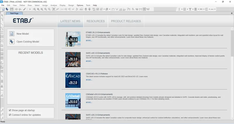
- Below image shows the first interface of the software. Initially this page opens up as we open the ETABS software.
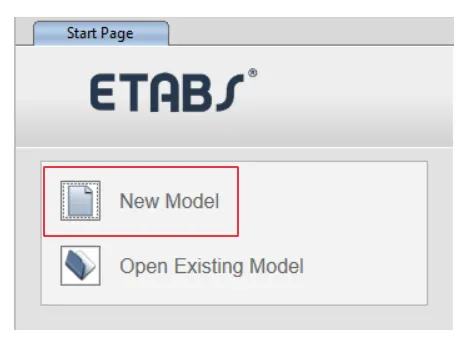
- After opening the software there is a home page where there is an option called New Model just click on that as shown in the below figure:
- After this another dialogue box opens as we select the option new model.
- A new window named as Model Initialization as shown in the below figure:
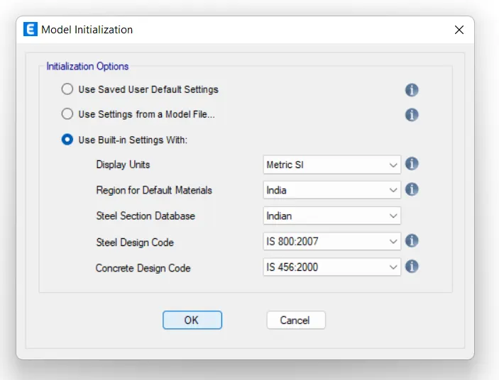
- In this dialogues box there are few Initialization options as we can see in the above image and these options are: Use Saved User Default Settings, Use Settings from a model file (we can use this option if we have already worked on some projects then this is the default setting) and the last option is Use Built-in Settings With (and we will be using this option now because this is the first time that we are working for ETABS software).
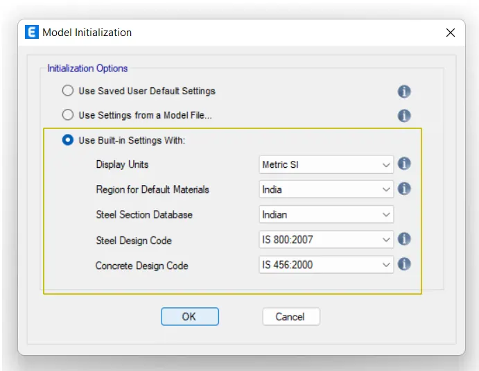
- As we are going to be working with the third option then after clicking on that option, we will be able to see that there are other options in the Use Built-in Settings With, and here are the options:
- Display units: Set it as Metric SI.
- Region for Default Materials: Set this as Indian.
- Steel Selection Database: Set it as Indian.
- Steel Design Code: Set it as IS 800:2007.
- Concrete Design Code: Set it as IS 456:2000.
- Now we are done with the Model Initialization. We have put all the necessary information regarding the modelling as we can see in the below image:
- After completing the Model Initialization process another dialouge box appears on the screen named as New Model Quick Template as shown in the below figure:
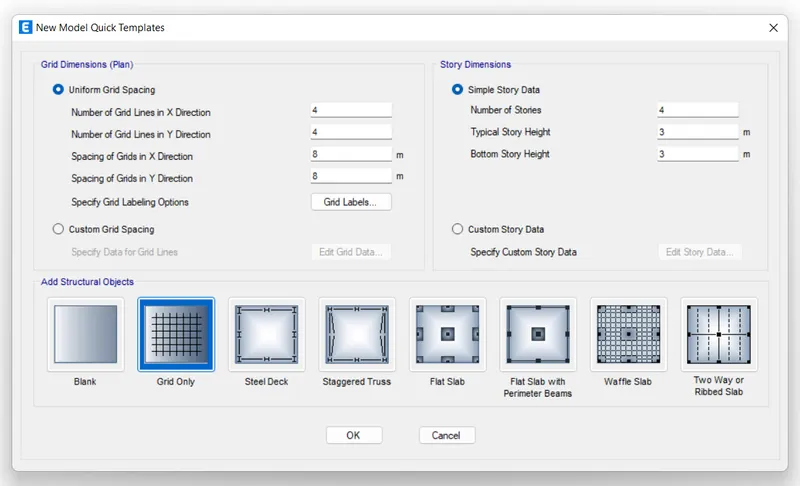
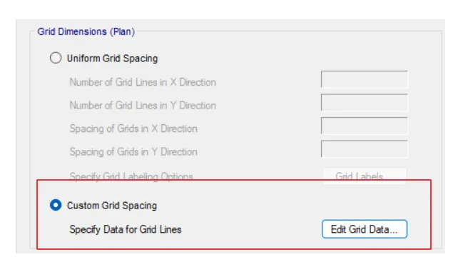
- First of all, we need to create grids according to the plan given in the question. So, for creating grids click on the option Custom Grid Spacing. There is another option called Edit Grid Data as shown in the below figure:
- After clicking on the option Edit Grid Data there is another window that opens named as Grid System Data as shown in the below figure:
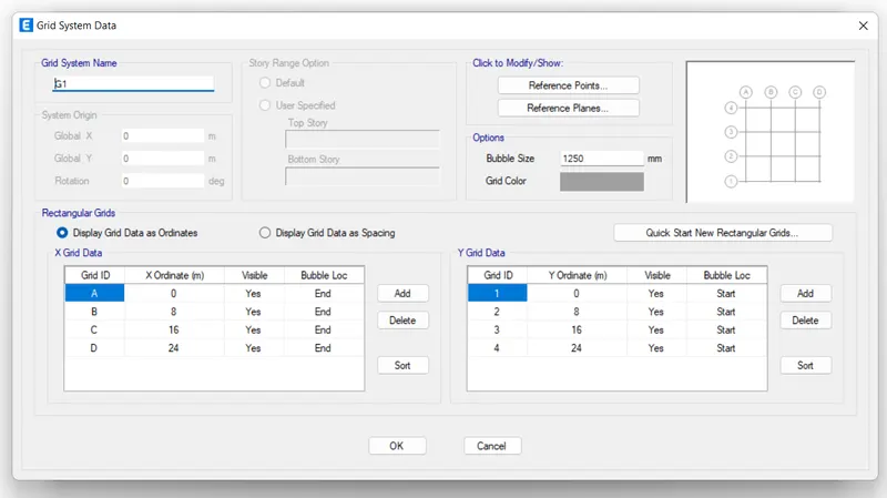
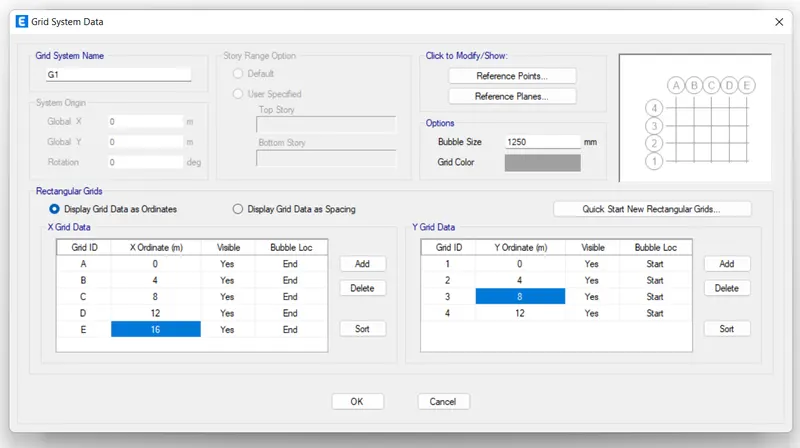
- Now set the all-necessary data in this Grid System Data option. Our X and Y grid sizes are 4 X 4. We have 3 columns and 4 rows that means we have 3 blocks in the Y-direction and 4 blocks in the X-direction.
- Now set the all-necessary data in the given table as shown in the below figure:
- After assigning the grids now we have to assign the number of story’s that our building has.
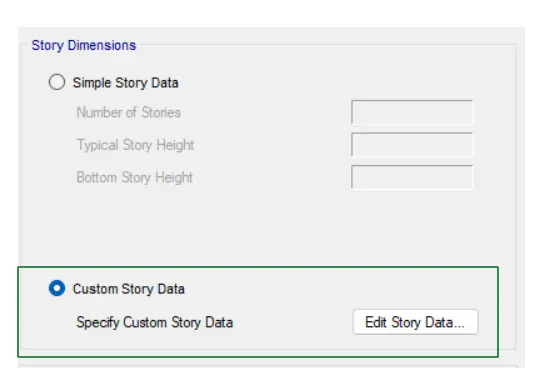
- So, in order to do that first we need to go to the option Custom Story Data and then click on the option Edit Story Data as shown in the below figure:
- After these new dialogues box appears on the screen as we can see in the below given image:
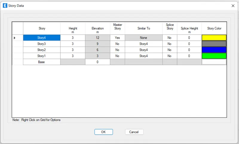
- So now here in this dialogue edit the stories and their heights and other necessary data.
- So, first of all click on the option story 1 in this dialogue box and rename it as Plinth Level and give it a height of 1.5 as mentioned in the above question itself as shown in the below figure:
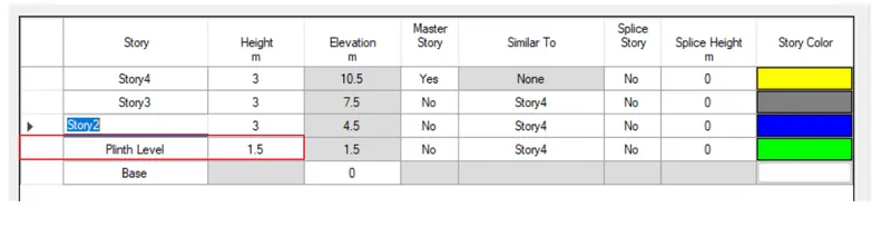
- And now go to the Story 2 option click there and type Storey 1 and give it a height of 3.
- Similarly click on the option Story 3 and give it of 3.
- Click on the option Story 4 and give it of 3 as shown in the below figure:
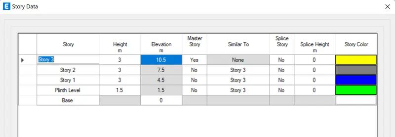
- We want 25 storeys so in order to add the more storeys in this box right click on the arrow and new box opens in that box there are many other options but we need to add the more storeys in this so just click on the option Add Story’s and then click on the option Keep Existing Story Heights as shown in the below figure:
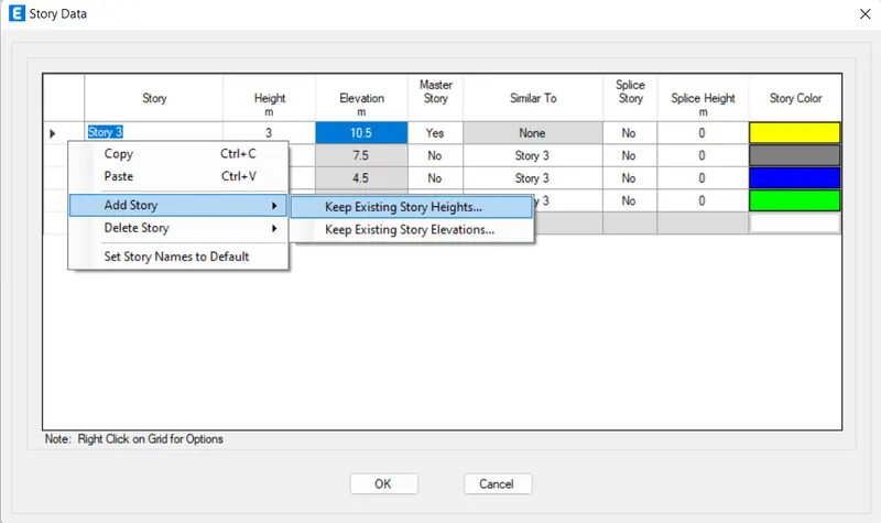
- after this another dialogue box appears on the screen named Add Story- Keep Existing Story Heights as shown in the below figure:
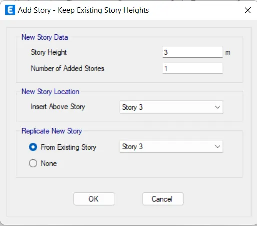
- Fill the all-necessary data:
- New Story Data:
- Story height: 3
- Number of Added Stories: 22
- New Story Location:
- Insert Above Story: Story 3.
- Replicate New Story:
- From Existing Story: Story 3
- And make the Story 1 as the Master story and the similar to Story 1.
- And then click on OK, as shown in the below figure:
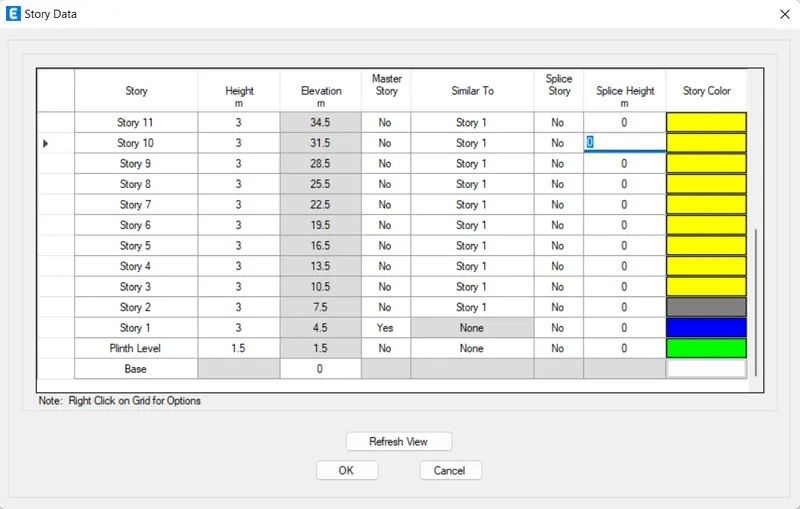
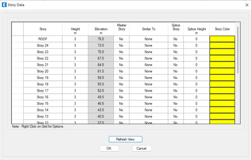
- Up to now we have set the grids and the number of stories and the basic few changes that will be needed in this modelling.
- Below is the image of how it will look like in the 3-D view and the plan view:
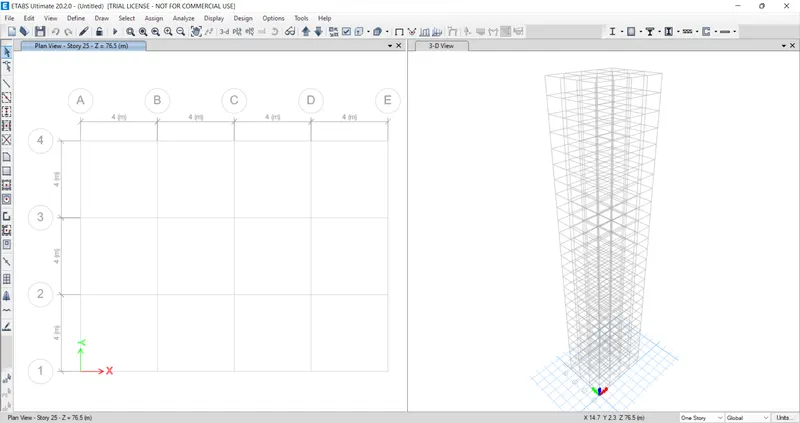
- After this we will be closing the 3-D view window and all the unnecessary viewports in order to focus on the floor plan.
- So, after closing the 3-D view we will be going to assign the materials.
- And to assign the material we need to go to the option called DEFINE in the file toolbar as shown in the below image:
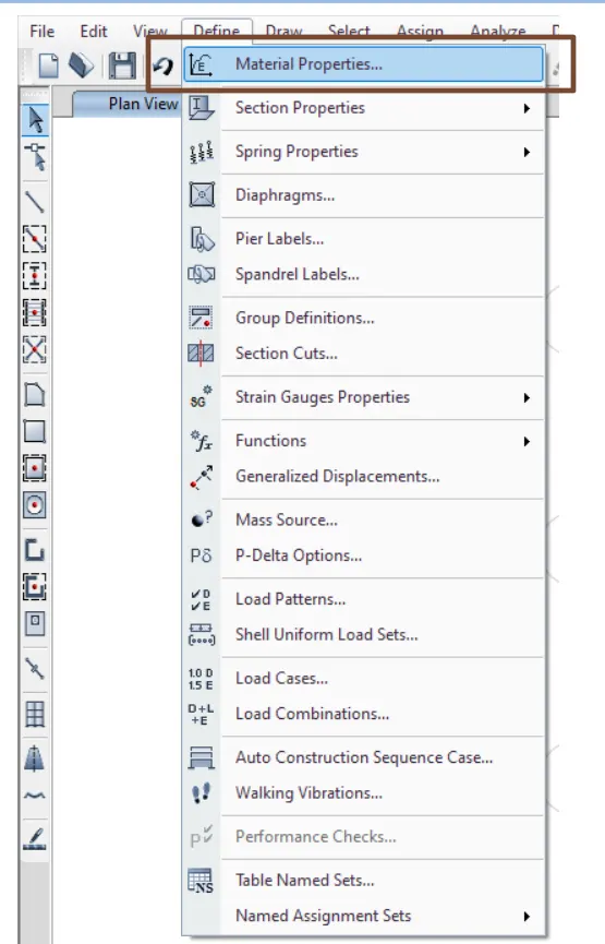
- After clicking on the Material Property option there will be another dialogue box opens named as Define Materials.
- From there dialogue box click on the option Add New Material as shown in the below figure:
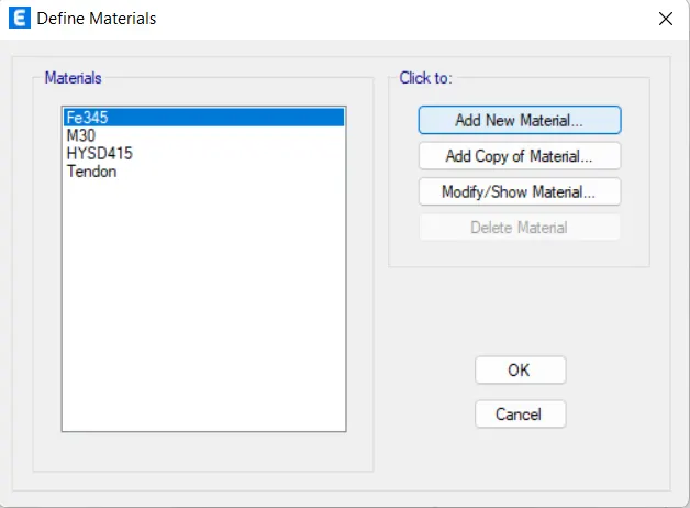
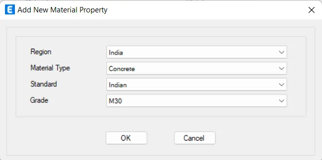
- After clicking on the Add New Material another dialogue box opens named as Add New Material Property, in that dialogue box there are few other options. Fill all the necessary details in those options. These options are:
- Region: Select as India.
- Material Type: Select as Concrete.
- Standard: Select as Indian.
- Grade: Select as M30.
- Click OK.
- After clicking OK there is another dialogue box that appears named as Material Property Data as shown in the below figure:
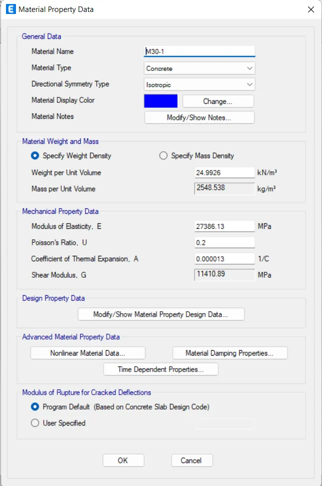
- In this dialogue box fill the necessary data that are required in modelling this building as shown below:
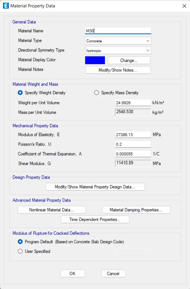
- After this go to the option Design property data and then click on the option Modify/Show Material Property Design Data and then there will be another dialogue box that opens named as Material Property Design Data as shown in the below figure:
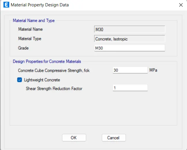
- Material Name and Type:
- Material Name: Type M30.
- Material Type: Concrete, Isotropic.
- Grade: M30.
- Design Properties for Concrete Materials:
- Concrete Cube Compressive Strength, fck: 30 MPa.
- Check on the Lightweight Concrete because it is a high-rise building.
- Shear Strength Reduction Factor: 1.
- And then click OK.
- Now the concrete material has been added into the list.
- Now we have to add the Rebar for the longitudinal reinforcement.
- So, in order to do that first we need to go to the option Add New Material as shown in the below figure:
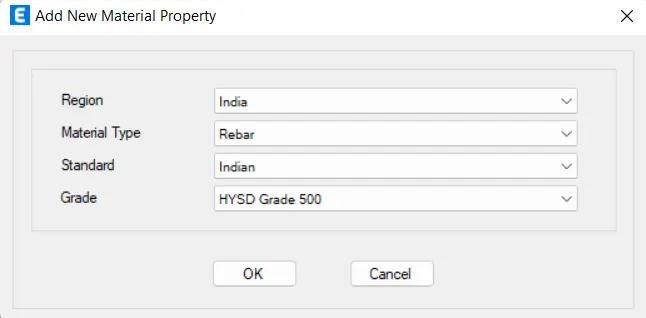
- After this a new dialogue box appears on the screen named as the Add New Material Property
- Fill all the necessary details like region, material type, standard etc:
- Region: Select India.
- Material Type: Select Rebar.
- Standard: Indian.
- Grade: HYSD Grade 500.
- as shown in the below figure:
- After filling out the all-necessary details in this section and then click OK.
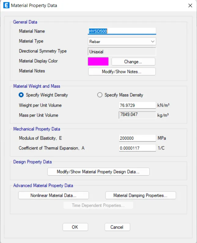
- Then there is another window that opens named as the Material Property Data in that window fill out the necessary information as shown in the below figure:
- Click OK.
- After this similarly add the rebars for the shear reinforcement, in order to do this process, go to the option Add New Material as shown in the below figure:
- After this a new dialogue box appears on the screen named as the Add New Material Property
- Fill all the necessary details like region, material type, standard etc:
- Region: Select India.
- Material Type: Select Rebar.
- Standard: Indian.
- Grade: HYSD Grade 415.
- as shown in the below figure:
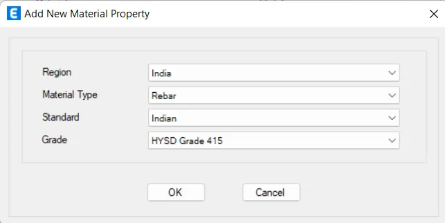
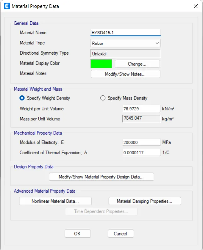
- After filling out the all-necessary details in this section and then click OK.
- Then there is another window that opens named as the Material Property Data in that window fill out the necessary information as shown in the below figure:
- Click OK.
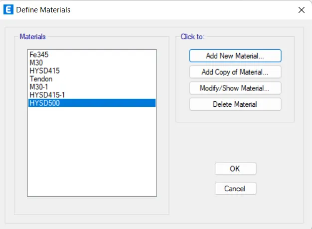
- Now the materials have been added as shown in the below figure:
- Click OK.
- After assigning the materials we will be assigning the Frame sections.
- In order to do that first do to the Detail option in the file toolbar as shown in the below figure:
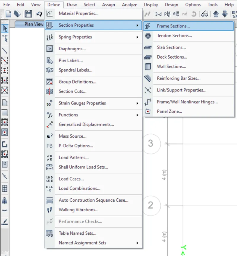
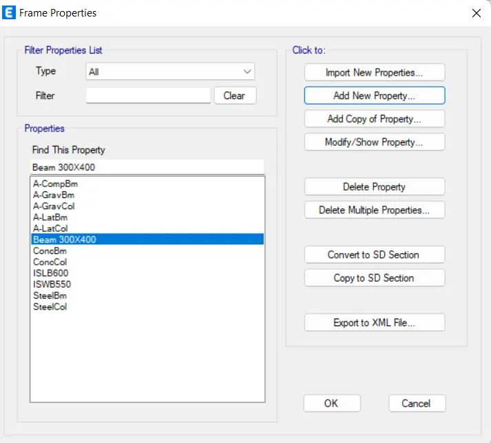
- After clicking on the option Frame Section, the new dialogue box appears on the screen, in that dialogue box there will be an option called Add New Property just click on that option as shown in the below figure:
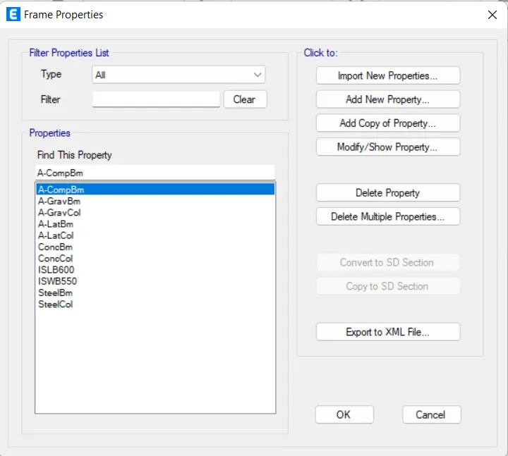
- After clicking on the option Add New property another dialogue box appears on the screen named as Frame Property Shape Type.
- From that dialogue box choose the desired shape, here I am choosing the Concrete rectangular as shown in the below image:
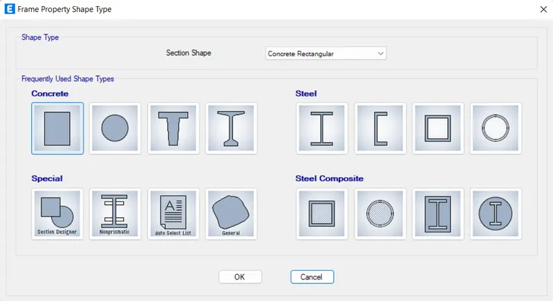
- Click OK.
- After clicking the OK there will be another dialogue box name as Frame Section Property Data as shown in the below figure:
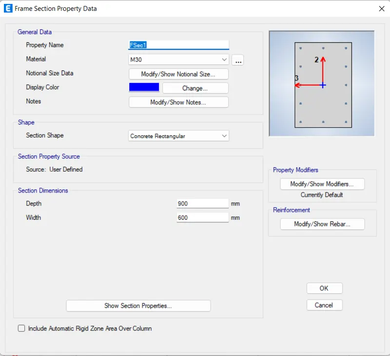
- In that dialogue box fill out the all-necessary data which is required to model this building as shown in the above figure.
- General data:
- Property Name: Type Beam 300X400.
- Material: M30.
- Shape:
- Section Shape: Concrete Rectangular.
- Select Dimensions:
- Depth: 400.
- Width: 300.
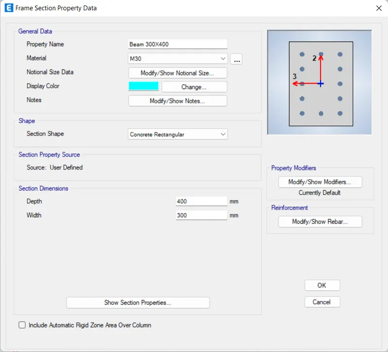
- And then click on the option Modify/Show Rebar option.
- Another window appears on the screen named as Frame Section Property Reinforcement Data as shown in the below image:
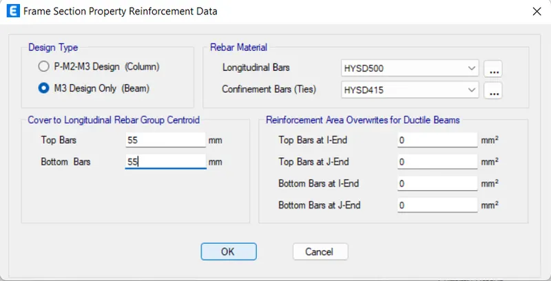
- Fill out the necessary details in that dialogue box.
- Design Type:
- Check on the option M3 Design Only (Beam).
- Rebar Material:
- Longitudinal Bars: Select HYSD500.
- Confinements Bars (Ties): HYSD415.
- Cover to Longitudinal Rebar Group Centroid:
- Top Bars: 55 mm.
- Bottom Bars: 55 mm.
- And then Click OK.
- Now click on the option properties Modifier in the Frame Section Property Data window as we can see in the below given image:
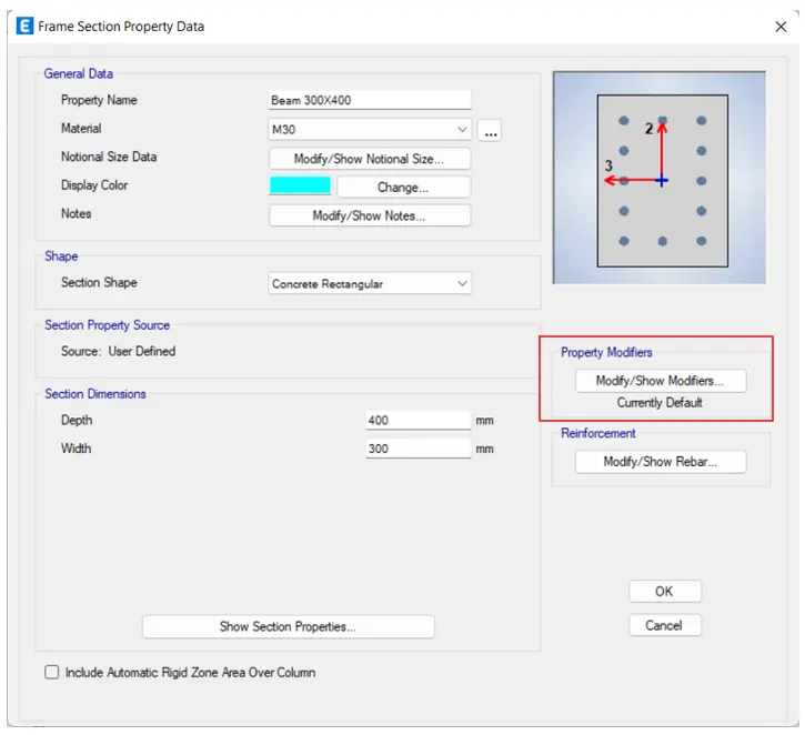
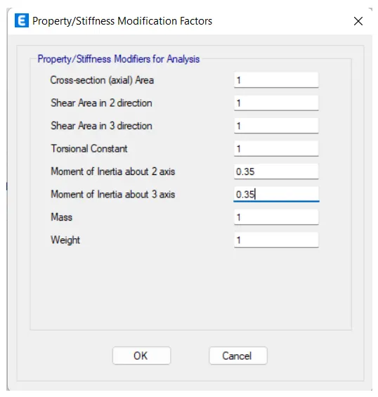
- After clicking on the Modify/Show Modifiers option a new window/dialogue box opens. In that box we need to change the Moment of Inertia about axis up to 35%.
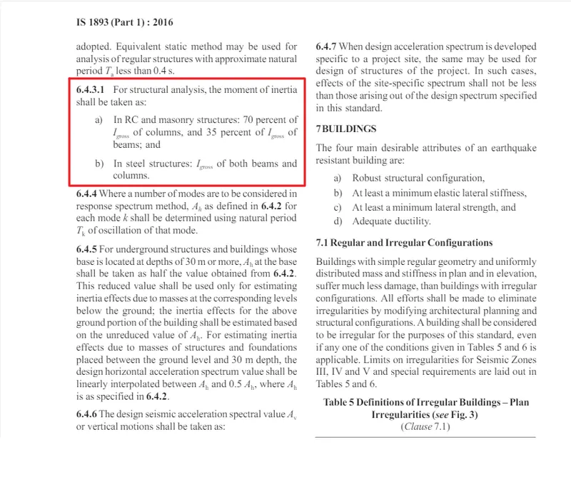
- Why do we change MI about 35%? Because of the Clause No. 6.4.3.1 in IS 1893 (Part 1):2016. Because this clause states that the Moment of Inertia about axis for beams should be 35% as we can see in the below image:
- So here we will change the Moment of Inertia up to 35% as we can see in the below image:
- After this click OK.
- The beams have been added.
- Now we will be adding the columns details.
- In order to add the column details as new element in the frame section, first go to the Define option in the file toolbar at the top of the screen and then go to the Frame section, as shown in the below figure:
- After clicking on the option Frame Section, the new dialogue box appears on the screen, in that dialogue box there will be an option called Add New Property just click on that option as shown in the below figure:
- After clicking on the option Add New property another dialogue box appears on the screen named as Frame Property Shape Type.
- From that dialogue box choose the desired shape, here I am choosing the Concrete rectangular as shown in the below image:
- Click OK.
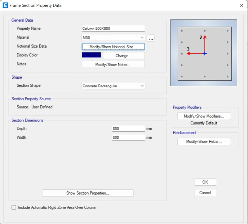
- After clicking the OK there will be another dialogue box name as Frame Section Property Data as shown in the below figure:
- In that dialogue box fill out the all-necessary data which is required to model this building as shown in the above figure.
- General data:
- Property Name: Type Column 800X800.
- Material: M30.
- Shape:
- Section Shape: Concrete Rectangular.
- Select Dimensions:
- Depth: 800.
- Width: 800.
- as shown in the below figure:
- And then click on the option Modify/Show Rebar option as shown in the below figure:
- Another window appears on the screen named as Frame Section Property Reinforcement Data as shown in the below image:
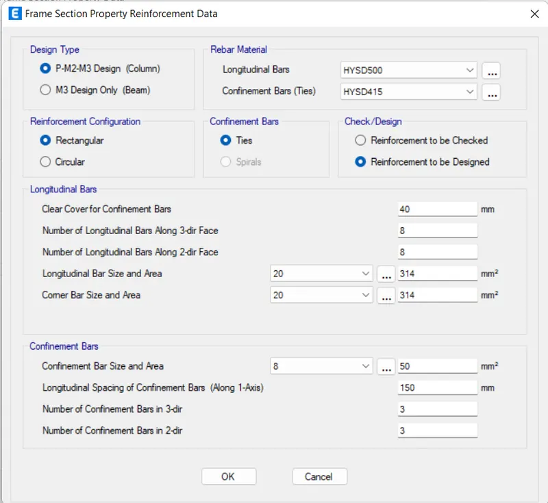
- Fill out the necessary details in that dialogue box.
- Design Type:
- Check on the option P-M2-M3 Design (Column).
- Rebar Material:
- Longitudinal Bars: Select HYSD500.
- Confinements Bars (Ties): HYSD415.
- Reinforcement Configuration:
- Check on the rectangular option.
- Confinement Bars:
- Check/Design:
- Check on Reinforcement to be designed.
- And all the other necessary data require.
- And now click on the option OK.
- Now go to the option Properties modifier at the right-hand side of the page.
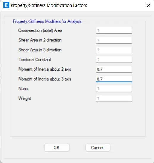
- And then after clicking on the Modify/Show Modifiers option a new window/dialogue box opens. In that box we need to change the Moment of Inertia about axis up to 70%.
- Why do we change MI about 70%? Because of the Clause No. 6.4.3.1 in IS 1893 (Part 1):2016. Because this clause states that the Moment of Inertia about axis for columns should be 70% as we can see in the below image:
- So here we will change the Moment of Inertia up to 70% as we can see in the below image:
- Now click the option OK.
- Now we are done with adding the columns and the beams as we can see in the below image:
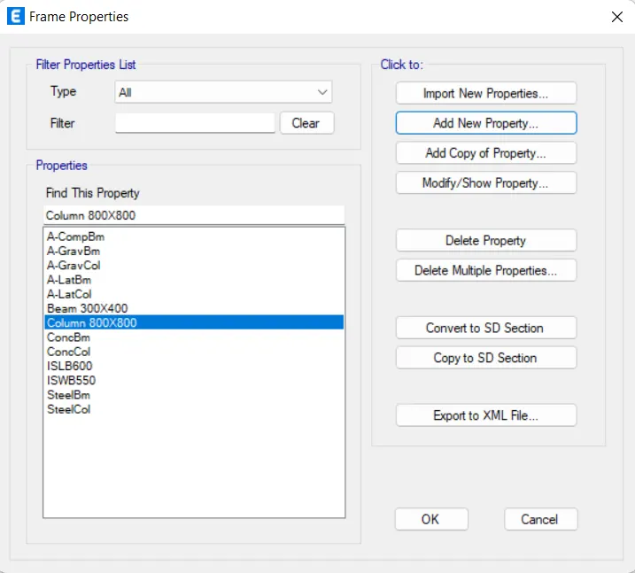
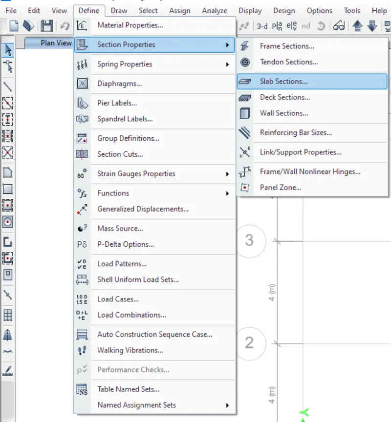
- After adding the columns and the beams, now we are going to add the slab of 150mm thickness.
- So, in order to add the slab, first we need to go to the Define option and then click the option Slab Sections as we can see at the below given image:
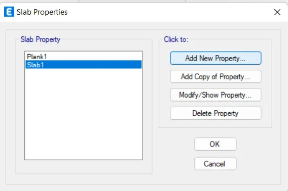
- After clicking on the slab sections option a new dialogue box appears on the screen named as Slab Properties and in this there is an option called Add New Property just click on that option as we can see at the below image:
- After clicking on the option Add New Property a new dialogue box opens called Slab Property Data as shown in the below image:
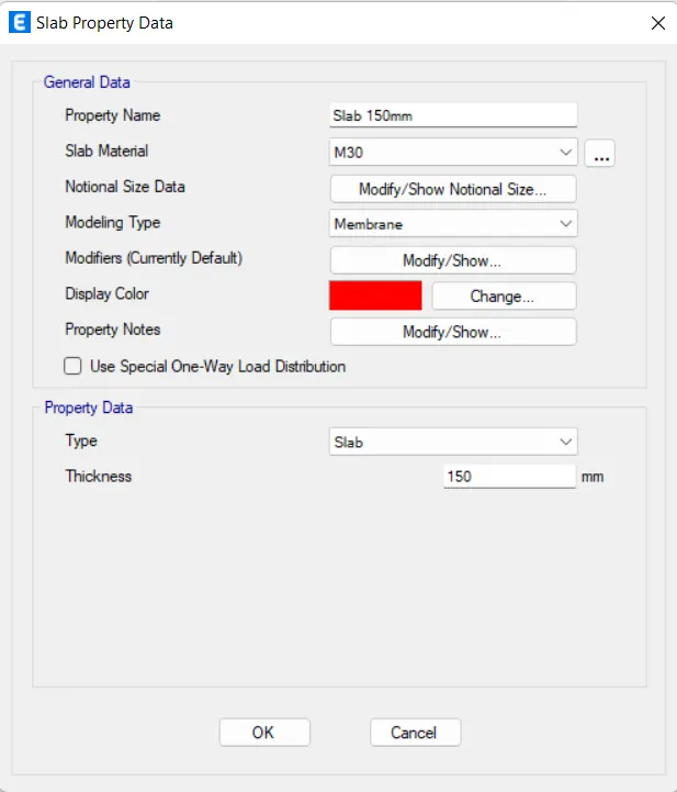
- Fill out all the necessary data.
- General data:
- Property Name: Slab 150 mm.
- Slab Material: M30.
- Modelling Type: Membrane
- We will not go to check the option Use Special One-Way Load Distribution because here all the slabs are two-way slab because the ratio of their length and the breadth is less than 2 i.e.,
- `frac{L}{B} = frac {4}{4} =1` which means all the slabs here are two-way slab.
- Property Data:
- Type: Slab.
- Thickness: 150 mm.
- After filling all the necessary data, we will be clicking on the OK option as we can see at the below given image:
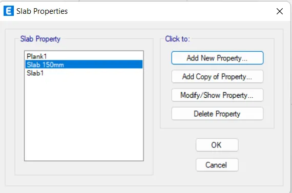
- Up till now we added beams, columns and the slab successfully.
- After this we will be drawing the columns at the plan.
- So, in order to create/draw the columns first we need to go to the plan view.
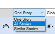
- Here select all storeys at the right bottom of the screen as we can see at the below given image:
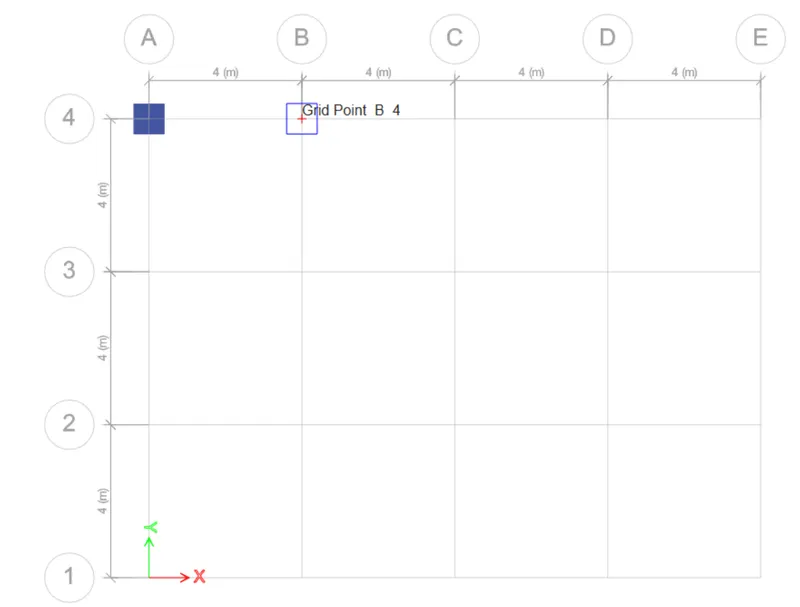
- Now to create the columns in a quick way we need to go to the option Quick Draw Columns which are present at the left side of the screen just click on that option as we can see at the below image:
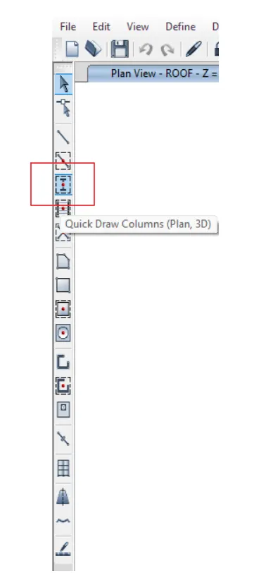
- After clicking on the option Quick Draw Columns there will be new dialogue box that opens called properties of the object.
- In that dialogue box we need to provide the all-necessary data as shown in the below figure:
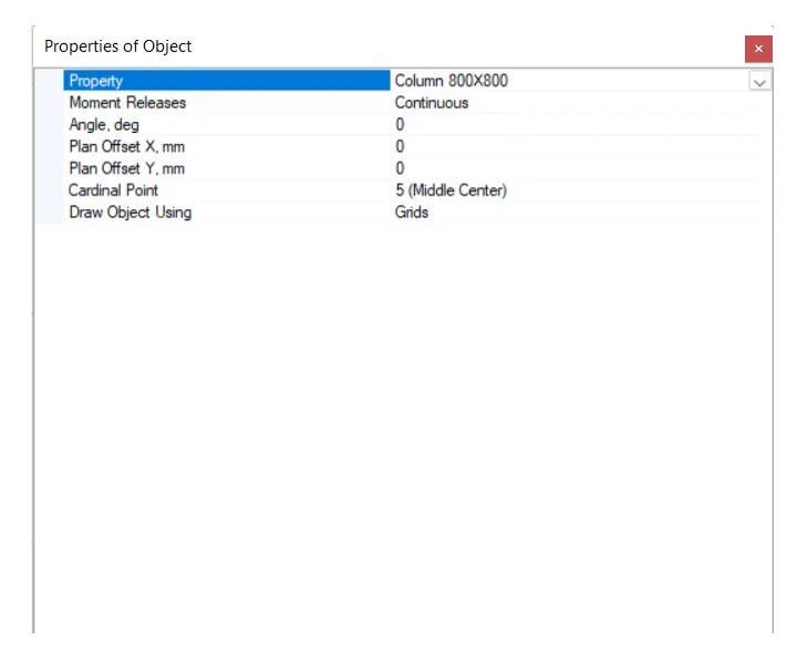
- Properties of Object:
- Property: Select Column 800X800.
- Moment Releases: Select Continuous.
- And then place the column accordingly. After using the Quick Draw Column option, it will become easier to draw the column. This option automatically tells the exact location or the mid-point where we have to put the column in the plan as we can see in the below image:
- Similarly place all the columns in the same way. After placing the columns in the plan, the plan will look like in the below given image:
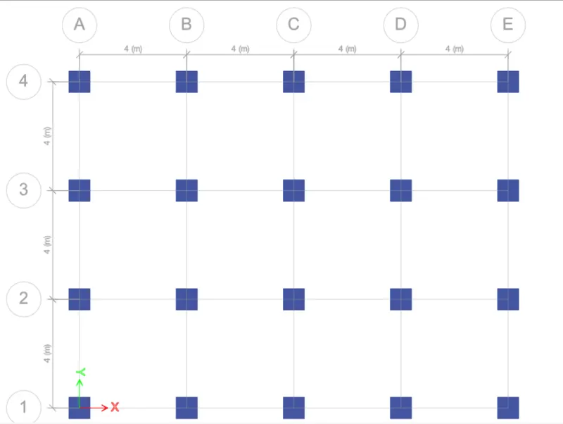
- The columns have been successfully placed at their places.
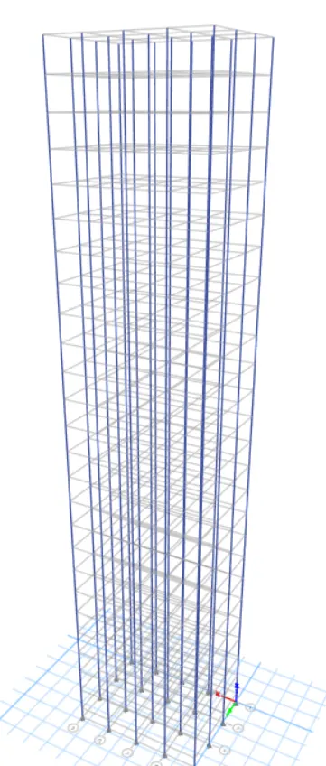
- We can see the column placement in the 3d view also if I have placed them correctly or not as we can see at the given below image:
- Now that the columns have been created, now we will be creating beams and these columns are joining with these beams.
- So, in order to create beams first go to the plan view and select all story at the right bottom of the screen as we can see at the below given image:
- Now to create the beams in a quick way we need to go to the option Quick Draw Beams/Columns which are present at the left side of the screen just click on that option as we can see at the below image:
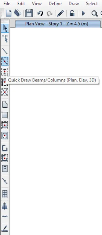
- After clicking on the option Quick Draw Beams/Columns there will be new dialogue box that opens called properties of the object.
- In that dialogue box we need to provide the all-necessary data as shown in the below figure:

- Properties of Object:
- Type of Line: Frame.
- Property: Select Beam 300X400.
- Moment Releases: Select Continuous.
- And then place the beams accordingly. After using the Quick Draw Beams/Column option it will become easier to draw the beams as we can see in the below image:
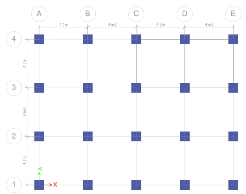
- Similarly place all the beams in the same way. After placing the beams in the plan, the plan will look like in the below given image:
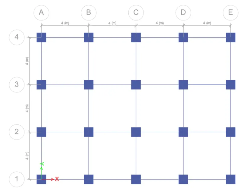
- The beams have been successfully placed at their places.
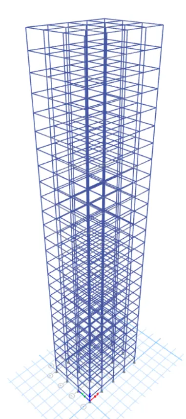
- We can see the beam placement in the 3d view aslo if i have placed them correctly or not as we can see at the given below image:
- After placing the columns and beams in the plan, now we have to place a slab.
- In order to place a slab in the plan first of all go to the plan view of the model and then go to the option Quick Draw Floor/Wall which is present at the left-hand side of the screen as shown in the below figure:
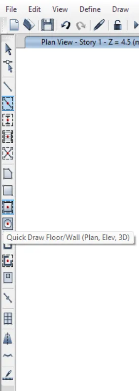
- After clicking on the option Quick Draw Floor/Wall there will be new dialogue box that opens called properties of the object.
- In that dialogue box we need to provide the all-necessary data as shown in the below figure:
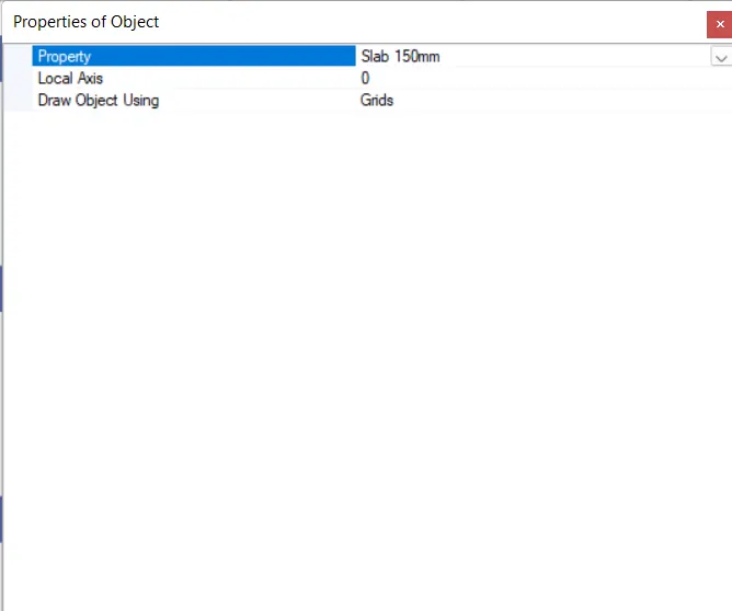
- Properties of Object:
- Property: Slab 150mm.
- Local Axis: 0.
- Draw Object Using: Grids.
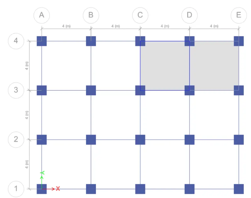
- And then place the slabs accordingly. After using the Quick Draw Floor/Wall option it will become easier to draw the slab just click in the centre of the grid then the slab will be automatically created just as simple as that, we can see in the below image:
- Similarly place all the slabs in the same way. After placing the slabs in the plan, the plan will look like in the below given image:
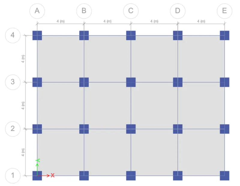
- The slabs have been successfully placed at their places.
- We can see the slab placement in the 3d view aslo if i have placed them correctly or not as we can see at the given below image:
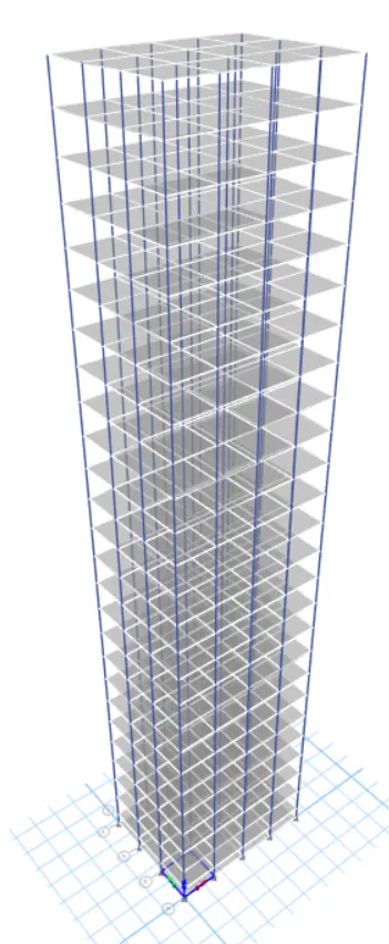
- After placing the slab on all the storeys, we will be assigning the base of the building as the pinned.
- In order to do that first we need to go to the plan view.
- And for assigning the base of the building we will be working on the base plan.
- And select only one story that is base storey because we have to assign the base.
- Now select all the joining points of the plan as shown in the below figure:

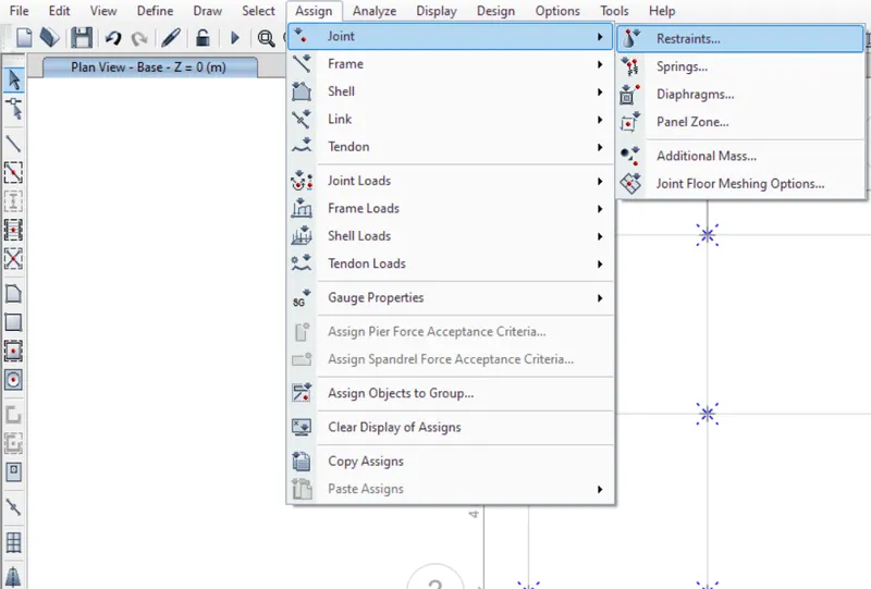
- Now go to the Assign option in the File toolbar then click on the Joint and then click on the Restraints as shown in the below image:
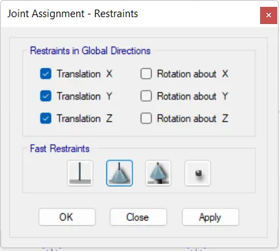
- After clicking on the option Restraints, a new dialogue box opens up named as Joint Assignment-Restraints.
- In that dialogue box there are other options in Fast Restraints column just click on the option Pin then select the base as pin as shown in the below image.
- And then click on the option APPLY and then OK.
- Now we will be adding the loads in the plan.
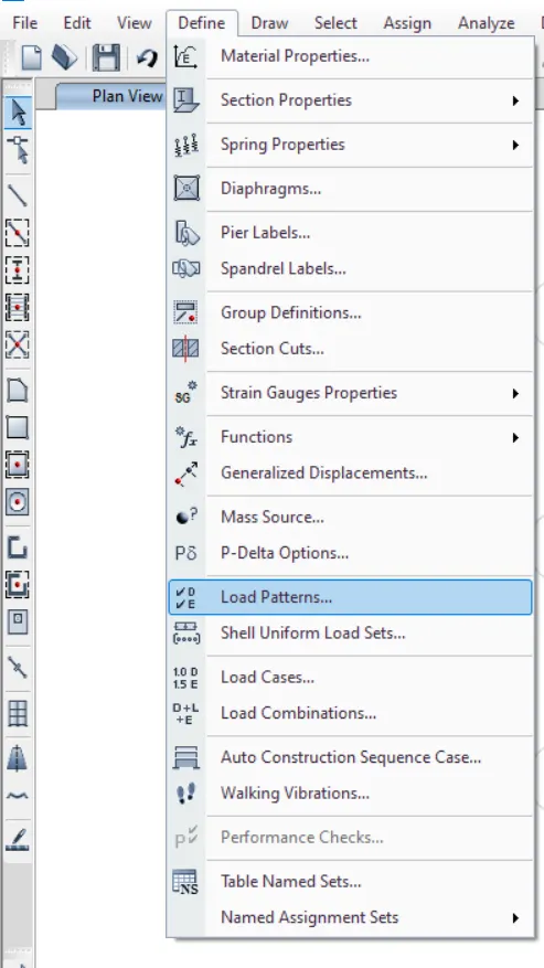
- So, in order to add these loads first go to the Define option which is present at the top of the ETABS screen and then click on the option Load Patterns just as shown in the below figure:
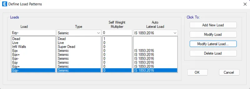
- After clicking on the Load Patterns option a new dialogue box opens named as Define Load Patterns just as shown in the below figure:
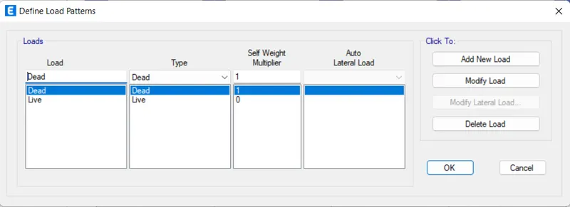
- Now we have to define the loads in the Loads sections like Loads (Dead load or live load or any other load), the type of load etc just fill this section with the appropriate loadings just as shown in the below figure:
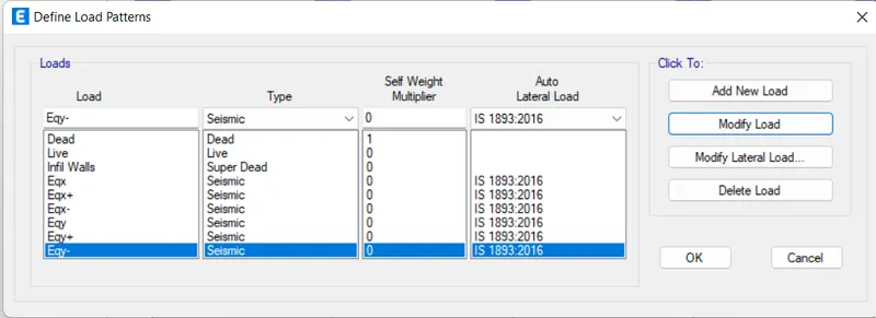
- Now the loads have been assigned accordingly as we can see at the above image.
- Now we have to edit the seismic loads like Eqx, Eqx+,Eqx- etc.
- So, in order to do that just click on the option Modify Lateral Load... and then a new dialogue box opens named as Indian IS 1893:2016 Seismic Loading as shown in the below figure:
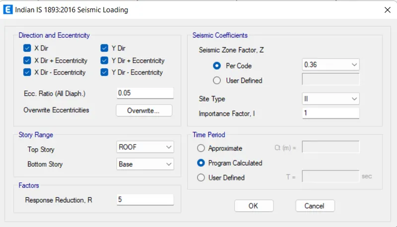
- First, we edit the Eqx load.
- For doing this we need to go to the option Modify Lateral Load... a new dialogue box opens.
- In that dialogue box fill out all the necessary details regarding the load Eqx just as shown in the below image:
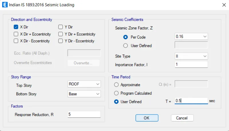
- Similarly do the same procedure for the Eqx+.
- For doing this we need to go to the option Modify Lateral Load... a new dialogue box opens.
- In that dialouge box fill out all the necessary details regarding the load Eqx+ just as shown in the below image:
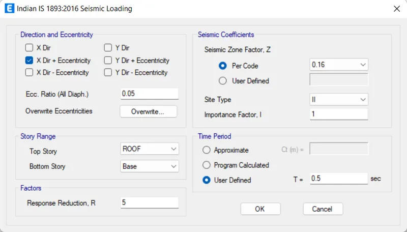
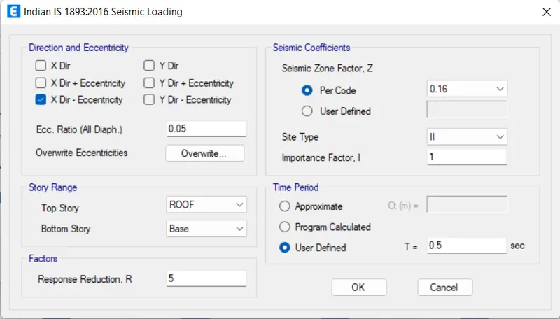
- For Eqx-.
- For doing this we need to go to the option Modify Lateral Load... a new dialogue box opens.
- In that dialogue box fill out all the necessary details regarding the load Eqx- just as shown in the below image:
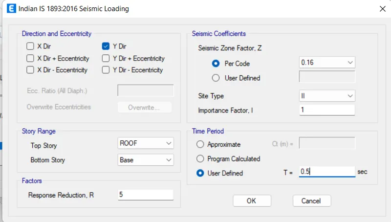
- Now similarly the same procedure for the Eqy as of the Eqx-.
- For doing this we need to go to the option Modify Lateral Load... a new dialogue box opens.
- In that dialouge box fill out all the necessary details regarding the load Eqy just as shown in the below image:
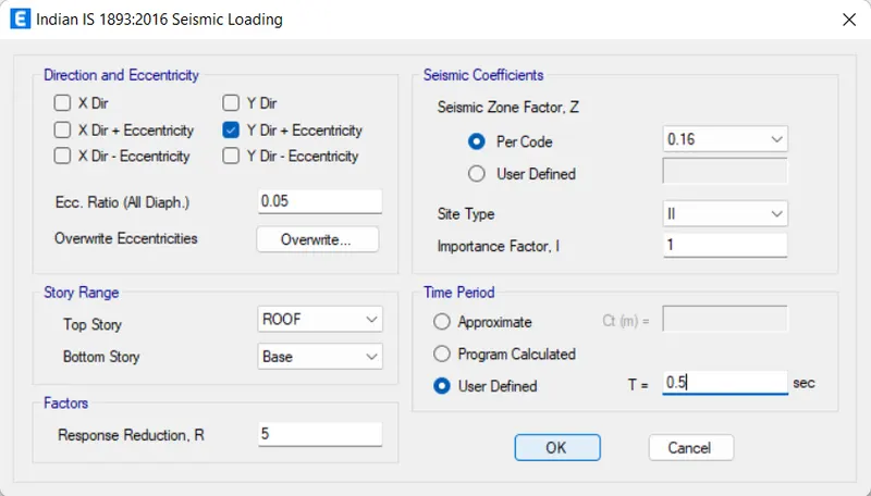
- Now similarly the same procedure for the Eqy+ as of the Eqx-.
- For doing this we need to go to the option Modify Lateral Load... a new dialogue box opens.
- In that dialouge box fill out all the necessary details regarding the load Eqy+ just as shown in the below image:
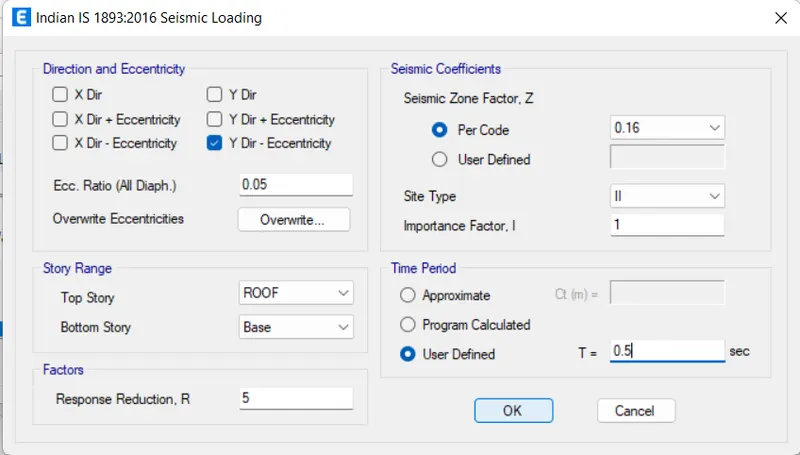
- Now similarly the same procedure for the Eqy- as of the Eqx-.
- For doing this we need to go to the option Modify Lateral Load... a new dialogue box opens.
- In that dialouge box fill out all the necessary details regarding the load Eqy- just as shown in the below image:
- At last, click OK as shown in the below figure:
- Now we will be assigning the live loads to this model.
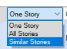
- In order to assign the live loads first we have to keep the storeys as the Similar Story we can find that option at the bottom of the right hand side of screen as we can see in the below given image:
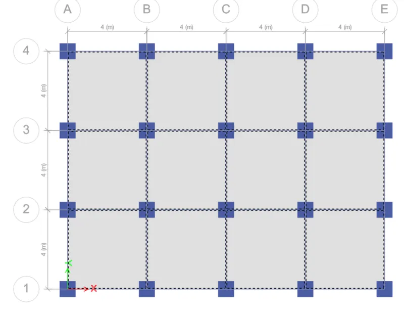
- After keeping the similar stories, we need to select the all shells as we can see in the below given image:
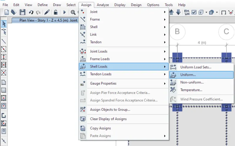
- After selecting the shells go to the option Assign at the top of the screen there will be an option called Assign and from that option there will be another option called Shell Loads from there select option Uniform and then clock just as shown in the below figure:
- After clicking the Uniform option from the Assign tab there will be another dialogue box named as Shell Load Assignment-Uniform as we can see in the below given image:
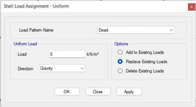
- Fill the all-necessary data in this dialogue box.
- Load Pattern:
- Load Pattern Name: Live.
- Uniform Load:
- Load: 3KN/m2.
- Direction: Gravity.
- Options:
- Check on the option Replace Existing Loads.
- And then click on the option Apply and then OK as shown in the below image:
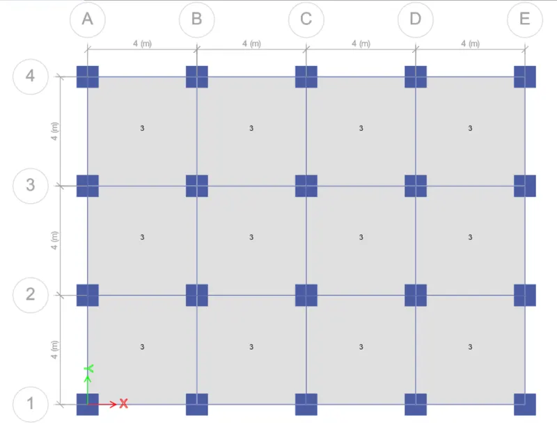
- After assigning the live loads now we will be assigning the loads on the brick wall or infill wall.
- In order to assign the loads on the infill walls.
- First, we have to go to the Select tab and then click on the option select and then Object Type which is seen at the upper side of the screen as shown in the below figure:
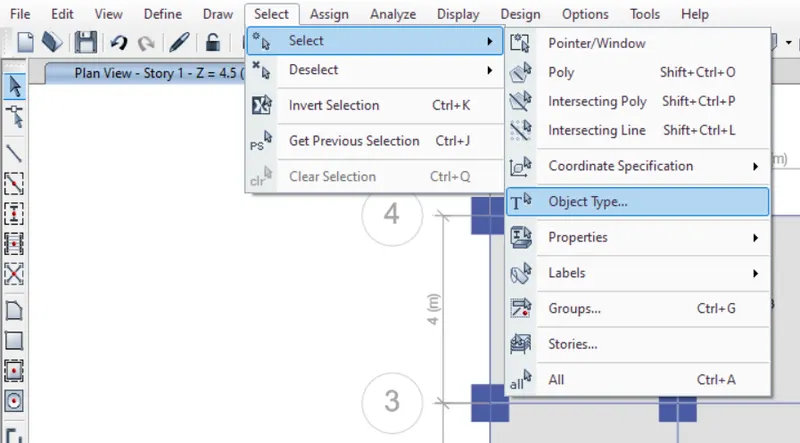
- After clicking on the Object Type option, a new dialogue box opens named as Select by Object Type here select the option Beams.
- After selecting the option beam just click on the option Select and then Close as shown in the below image:
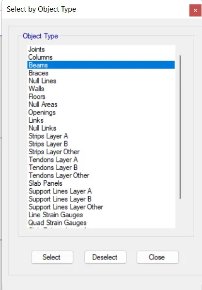
- By doing this all the beams have been selected just by a single click.
- After this go to the Assign tab at the top of the screen and there select option Frame Loads and then option Distributed just as shown in the below figure:
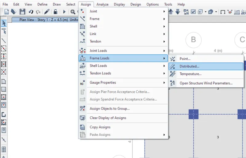
- After selecting the option Distributed another dialogue box appears on the screen named as Frame Load Assignment-Distributed just fill out the all-necessary information just as shown in the below figure:
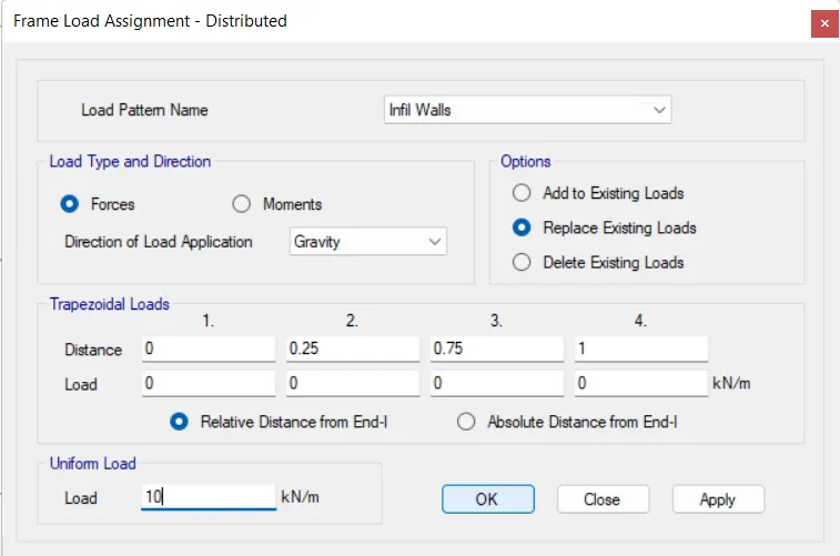
- After that just click on the option Apply and then OK.
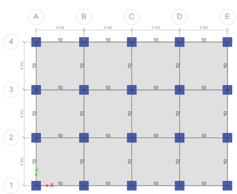
- Now the 10 KN/m loads have been applied on all the infill walls as shown in the below image:
- After assigning the loads on the infill mass now we will be assigning the mass source.
- In order to do that go to the Define tab and then click on the option Mass Source as shown in the below figure:
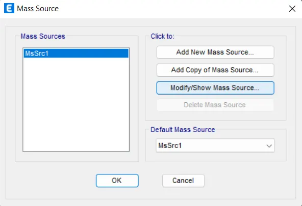
- After clicking on the Mass Source option, a new dialogue box appears on the screen from there select option Modify/Show Mass Source.
- After selecting the Modify/Show Mass Source another dialogue box appears named as Mass Source Data as shown in the below image:
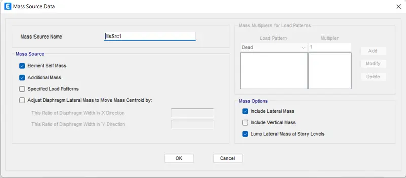
- Fill out all the necessary data in this section as shown below in the given image:
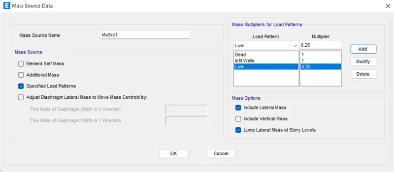
- And then click OK.
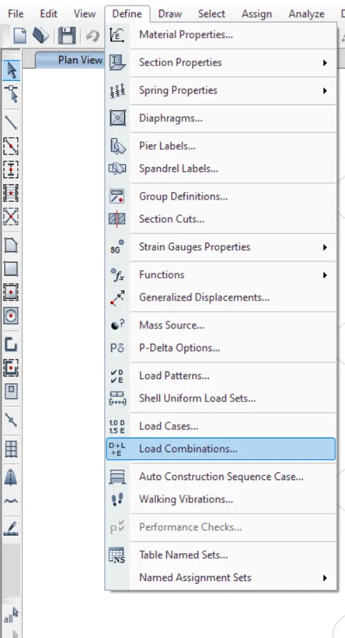
- After assigning the loads on the infill mass now we will be assigning the load combinations.
- So, in order to do that go to the Define tab which is present at the top of the ETABS screen just click on the Define tab and then click on another option named load combination just as shown in the below image:
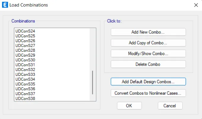
- After clicking on the Load Combination, a new dialogue box opens named as Load Combinations.
- And then click on the option Add Default Design Combos as shown in the below image:
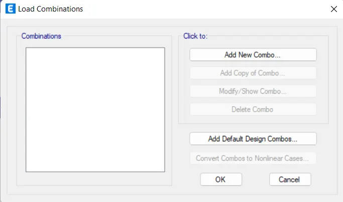
- After clicking on the option Add Default Design Combos there will be another dialogue box that opens named as Add Default Design Combinations as shown in the below given figure:
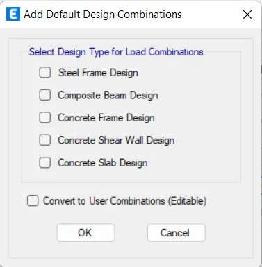
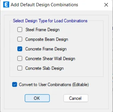
- In that dialogue box just click on the option Concrete Frame Design and check on the Convert to User Combinations (Editable) just as shown in the below figure:
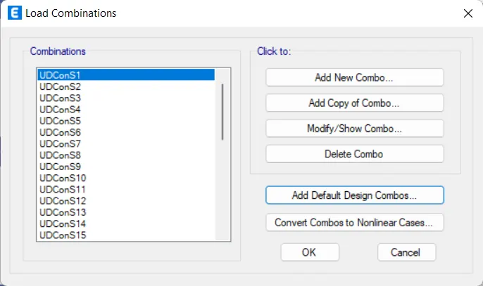
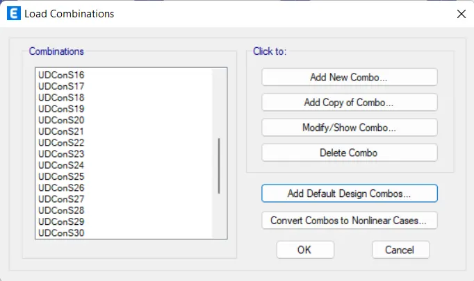
- Now the load combinations already have been created by the software itself we can see the loadings in the below given image:
- Now after assigning the load combinations, we will be assigning the diaphragm.
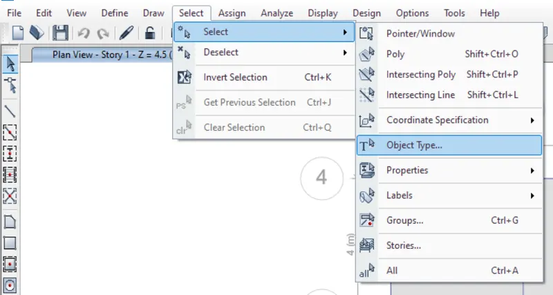
- And in order to do that first we have to go to the option Select which is present at the top of the screen then click on the option Select and then go to the option Object Type and then option Floor just as shown in the below image:
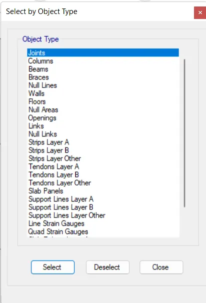
- After clicking on the Object Type there will be another dialogue box named as Select by Object Type as shown in the below image:
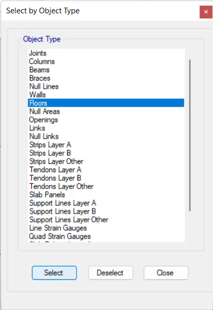
- Select the object type as Floor and then click on the option Select ad then Close as shown in the below image:
- Now click on the option Assign and then select Shell and then Diaphragms as shown in the below figure:
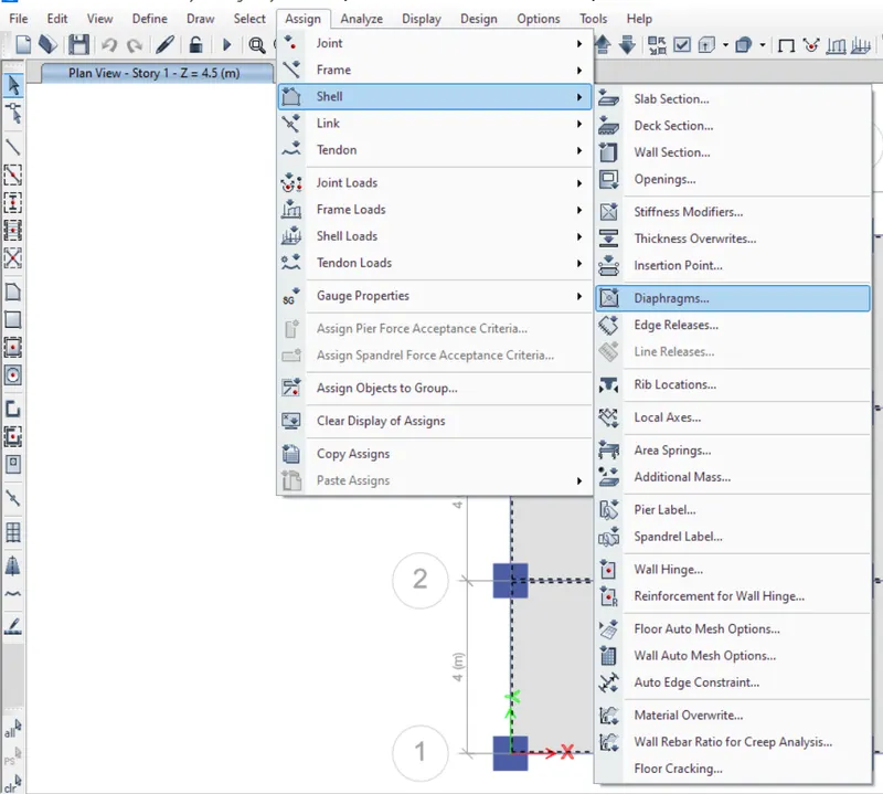
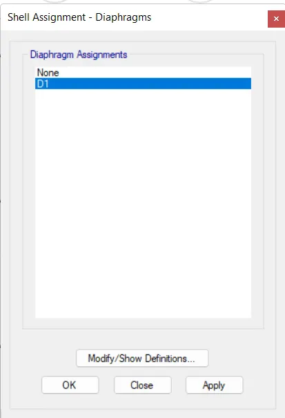
- After clicking on the option Diaphragms there will be another dialogue box named as Shell Assignment- Diaphragms.
- Click on the option D1 and then click on the option Apply and then OK as shown in the below image:
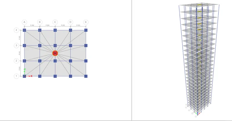
- After clicking on the option Apply The below is the result:
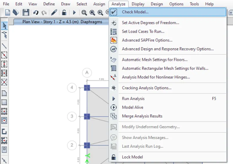
- And now after assigning the diaphragm now we will be doing Model Check.
- So, in order to do the Model Check first we go to the file tab there will be an option called Analyse click on that option after that click on the option Check the model just as shown in the below image:
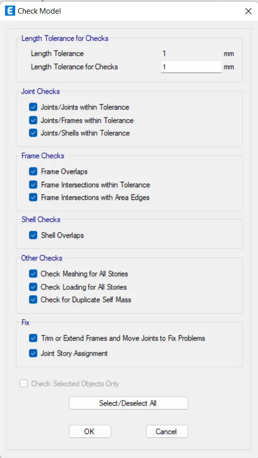
- After this a new dialogue box appears on the screen named as Check Model.
- In that dialogue box just click on all the other options.
- And then just click OK just as shown in the below image:
- After clicking on the OK option, the new window named as Warnings opens up to show any warning just as shown in the below image:

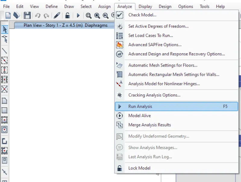
- Now we will be doing run analysis.
- In order to do the Run analysis just press f5 or there is an option in the Analyse tab as shown in the below image:
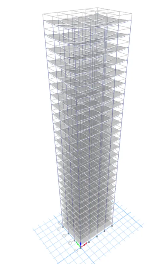
- This is how the building will look like after the analysis shown in the below image:
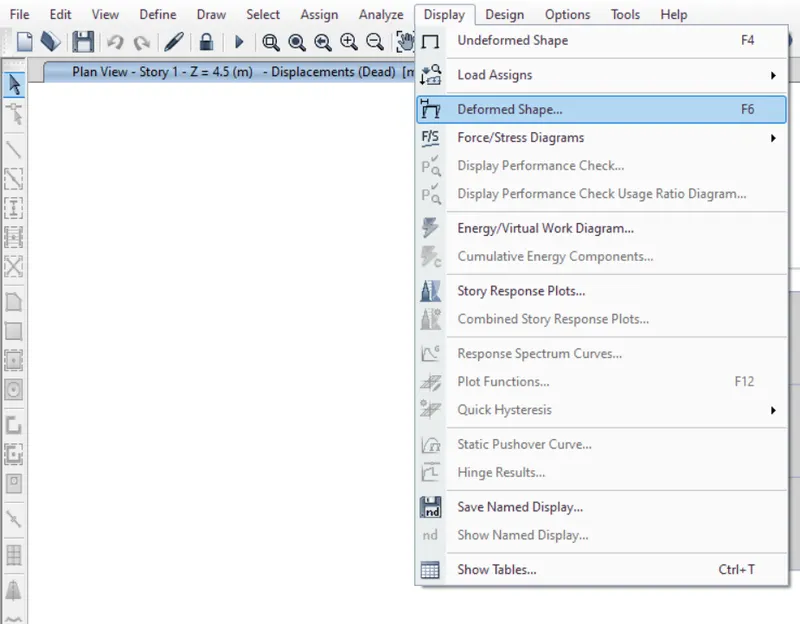
- Now we will be checking for the deflections in the given model.
- In order to do the deflection, go to the Display toolbar and then Deformed Shape just as shown in the below figure:
- Another dialogue box appears on the screen called Deformed shape fill out the all-necessary data just as shown in the below images:
For Dead Load:
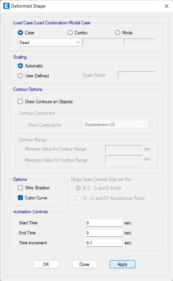
- Then click on the option Apply and then Ok
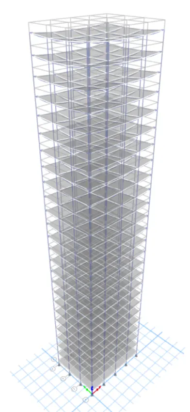
- For dead load below is the result:
For Live Load:
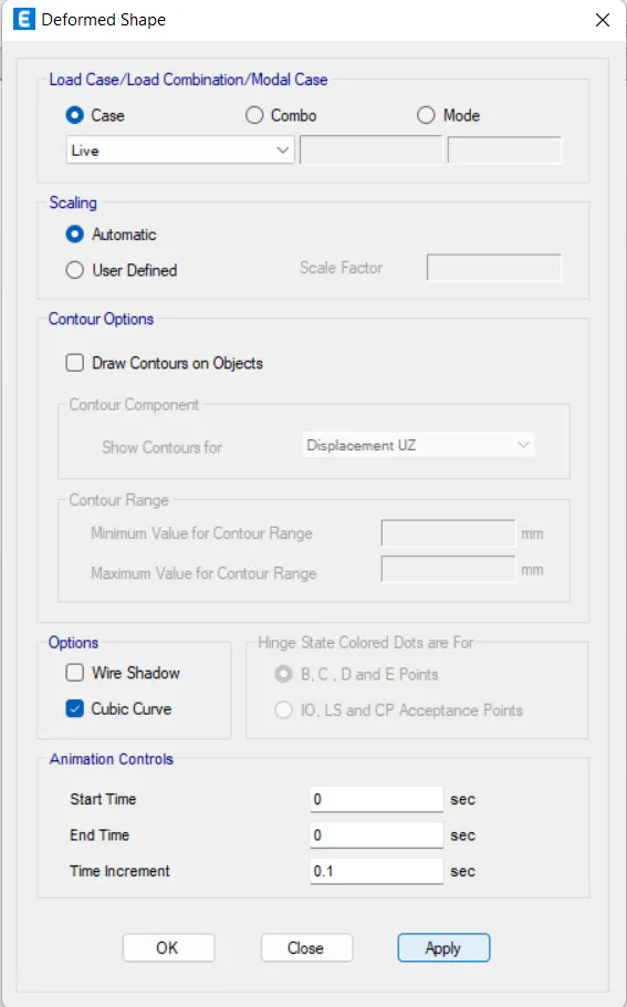
- Then click on the option Apply and then Ok
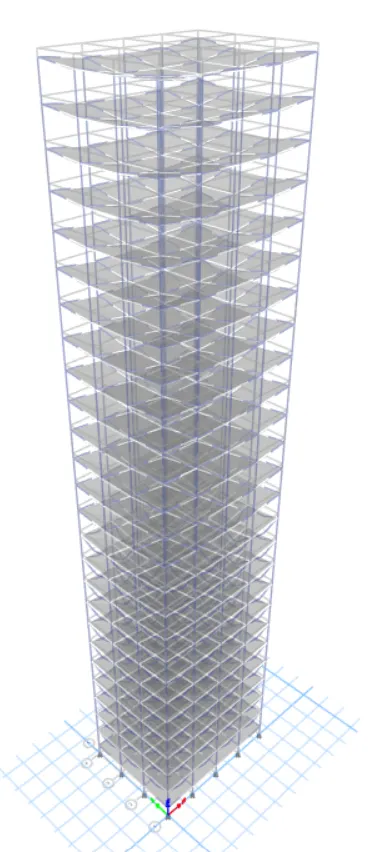
- For live load below is the result:
For Eqx:
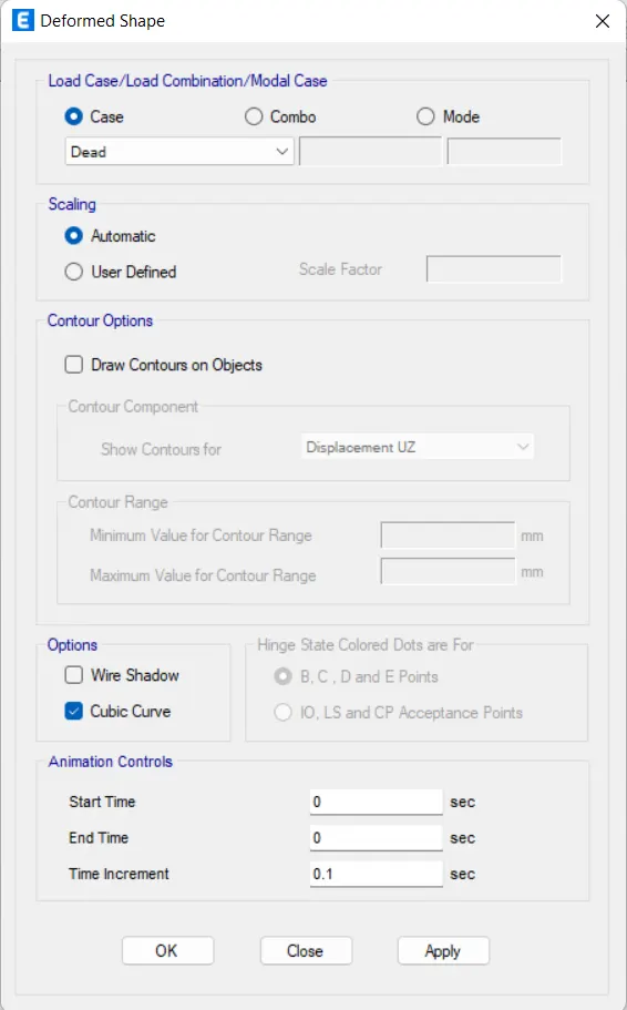
- Then click on the option Apply and then Ok
- For Eqx below is the result:
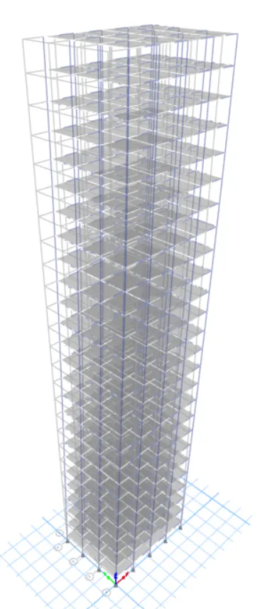
For Eqx+:
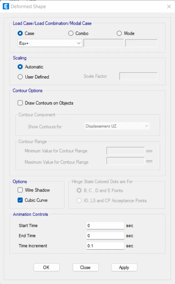
- Then click on the option Apply and then Ok
- For Eqx+ below is the result:
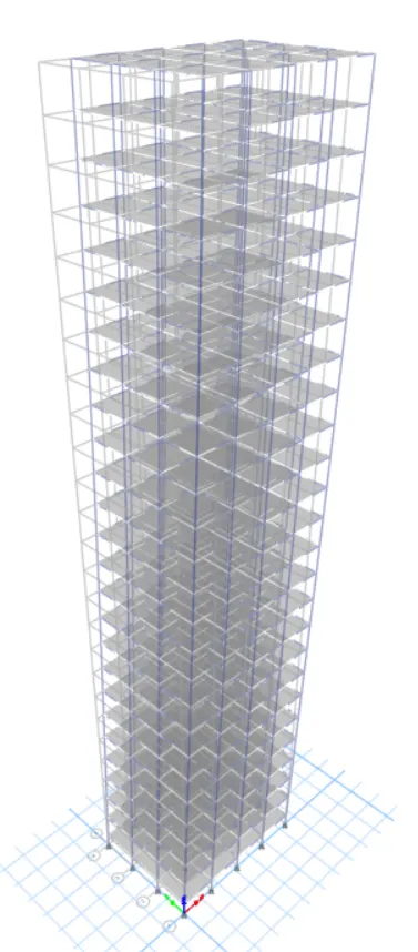
- Similar do the same procedure for all the loadings like Eqx-,Eqy,Eqy+,Eqy- etc.
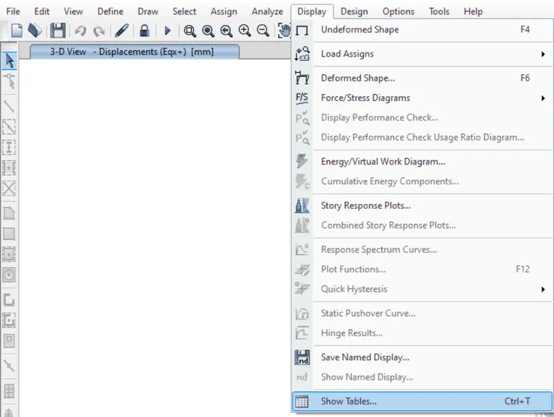
- Now for the base reaction Modal Periods and Frequencies.
- For to do that first we need to go to the Display toolbar present at the top of the screen and then click another option show tables just as shown in the below image:
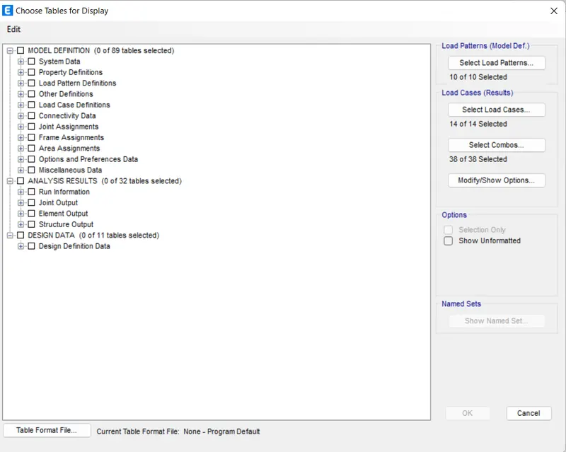
- After this a new window opens named as Choose Tables for Display just shown in the below image:
- In this dialogue box we will be choosing the settings just as shown in the below image:
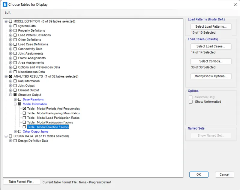
- And now click OK.
- And a new dialogue box appears on the screen named as Modal Periods and Frequencies which shows us the analysis result which is shown in the below given image:
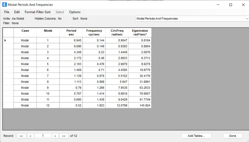
The value for Tx1 = 6.945
The value for Ty1 = 6.696
- Now we will be checking for the modal results (Modal Participating Mass Ratios).
- For this first we need to go to the Display toolbar present at the top of the screen and then click another option show tables just as shown in the below image:
- After this a new window opens named as Choose Tables for Display just shown in the below image:
- In this dialogue box we will be choosing the settings just as shown in the below image:
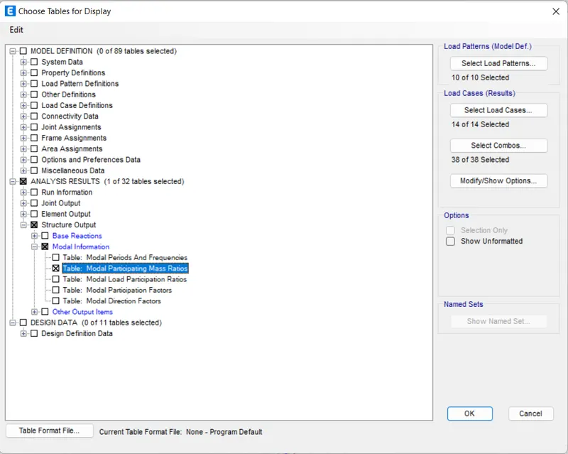
- And now click OK.
- And a new dialouge box appears on the screen named as Modal Periods and Frequencies which shows us the analysis result which is shown in the below given image:
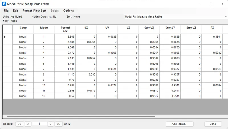
- So, the modal mass participation ratios that are obtained can be seen in the above graph. So, the first three mode of vibration in the x-direction are:
- 8054
- 0954
- 033
- Now we will analyse the result for the Story drift.
- In order to do that first we have to go to the Display toolbar which is present at the top of the screen and then go for the option Story Response Plot just as shown in the below image:
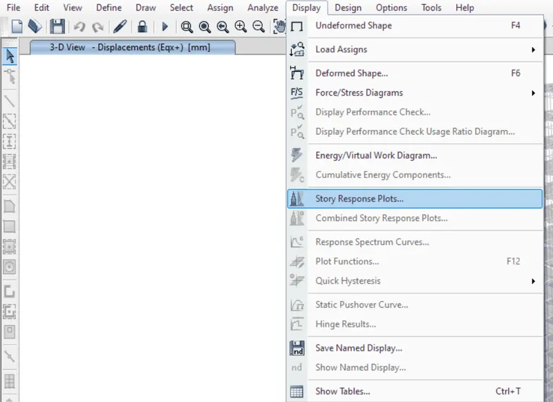
- After clicking on the Story Response Plot a new dialogue box appears on the screen named as Story Response.
- In that window at the left-hand side there are options available in that portion fill out all the necessary data just as given in the below image:
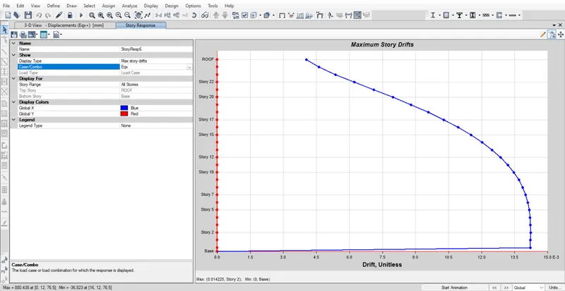
- Now we will be doing the checks:
- Check if the translational fundamental natural period of vibration in both the x and y direction is approximately: Tx1">Tx1Tx1= 4.4 second Ty1">Ty1Ty1= 4.2 second
- This check will help confirm if modelling is done correctly. Some deviations from the above values are possible (± 2%). But any major deviation will suggest an error in modelling.
Answer: - Here obtained are given below from the above observations:
- Tx1 = 6.945
- Ty1 = 6.696
The above values for the Tx1 and the Ty1 are 6.945 and 6.696 deviations from the above values is possible (± 2%). which means the modelling is correct.
- Check if the following provision in Table 5 of IS 1893 (part 1) – 2016, on torsional irregularity satisfied:
- The natural period corresponding to the torsional mode of oscillation must be less than the two fundamental translational modes of oscillation along each principal plan directions.
Answer: - So, the natural period corresponding to the torsional mode of oscillation must be less than the two fundamental translational modes of oscillation along each principal plan directions.
The obtained natural periods corresponding to the Translational mode are:
- 6.945
- 6.696
And the Natural Period corresponding to the Torsional mode is:
- 4.349
Hence, The Natural Period corresponding to the Torsional mode is less than the Natural Period corresponding to the Transitional Modes.
- Hence it satisfies the condition which is prescribed in the provision in Table 5 of IS code 1893 Part1.
- Check if the two provisions of clause 7 in Table 6 (shown below) of IS 1893 (part 1) – 2016, regarding vertical irregularity is satisfied
Answer: -
- The first condition is the first three modes together contribute at least 65 percent mass participation factor in each principal plan direction.
- So modal mass participation ratios the first three modes of vibration in the x-direction are given below:
- 8054
- 0954
- 033
- And the addition of these modal mass is: 93.38%.
- Therefore, the combination of the modal mass participation ratio is 93.38% which is higher than the 65% as per the IS code 1893.
- Hence the first condition is satisfied.
- The second condition is the fundamental lateral natural periods of the building in the two principal plan directions are away from each other by at least 10% of the larger value.
- So, the difference between the X and Y time periods are: 6.945-6.696 which is equal to 0.249 which is 6% of the larger value so the second condition is not satisfied.
- Here we can see that the first condition is satisfied but the second condition is not satisfied.
- Check if provision on inter-storey drift limitations in clause 7.11.1.1 satisfied. Please note that this check is for Serviceability Limit State and hence is for situation when structure is subjected to unfactored seismic base shear
Answer: - As we can see in the above graph the Maximum storey drift is 0.0135 which is higher than the 0.004.
RESULT: -
As we can see that the checks and the analysis of the 25-storey building has been completed. And all the checks satisfy their conditions except the last clause that is clause no 7. It doesn’t satisfy the given clause. Otherwise, all the clauses have been satisfied as we can see at the above checks and the analysis.
Here the analysis of the 25-storey building has been completed.