Modelling of 25 storey building with the specified properties using ETABS
Aim: To do modelling of 25 storey building with specified properties using ETABS software.
Procedure:
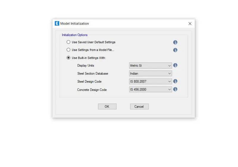
We need to open ETABS software and we should make settings as shown below
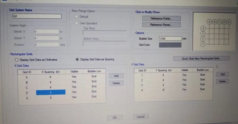
we will now see an interface as shown below,we need to click on custon grid spacing and custom story.
Maintain the spacing as 4m both in X and Y direcctions.
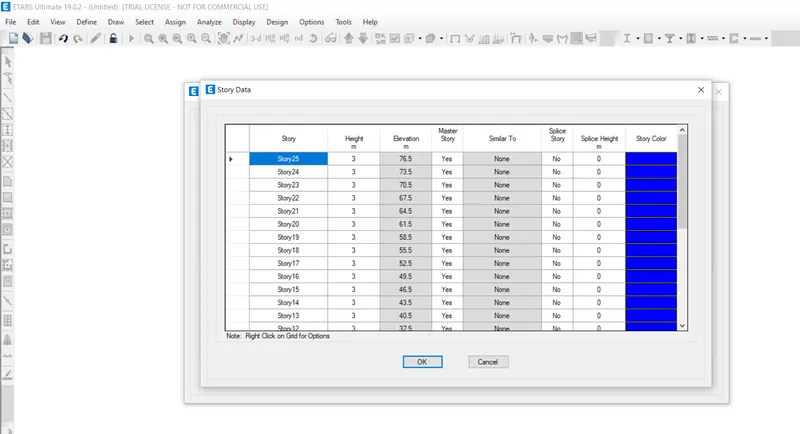
Now, click on ok and enter the stories up to 25 and a roof with a height of 3m for each and
except for base to plinth height which is 1.5m generally.1st storey is considered as the master story.
And required settings are made as shown below.
And when we click on ok ,we can see the following display.
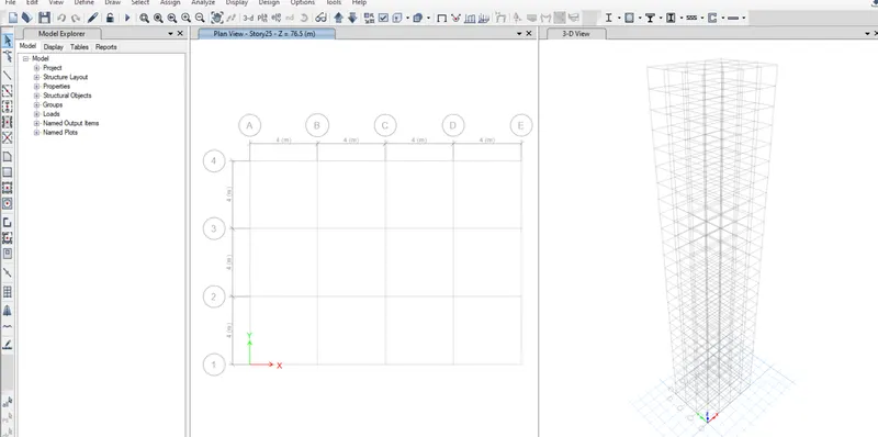
At this stage,click on define and go to select material properties and enter the following.
M30 grade concrete and steel 415.
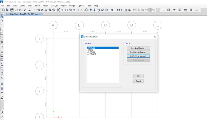
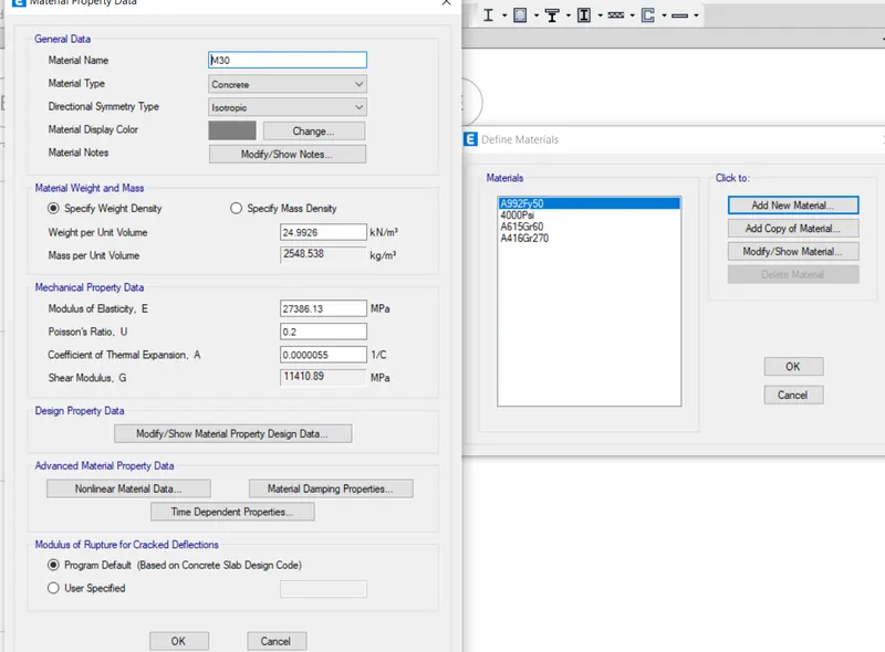
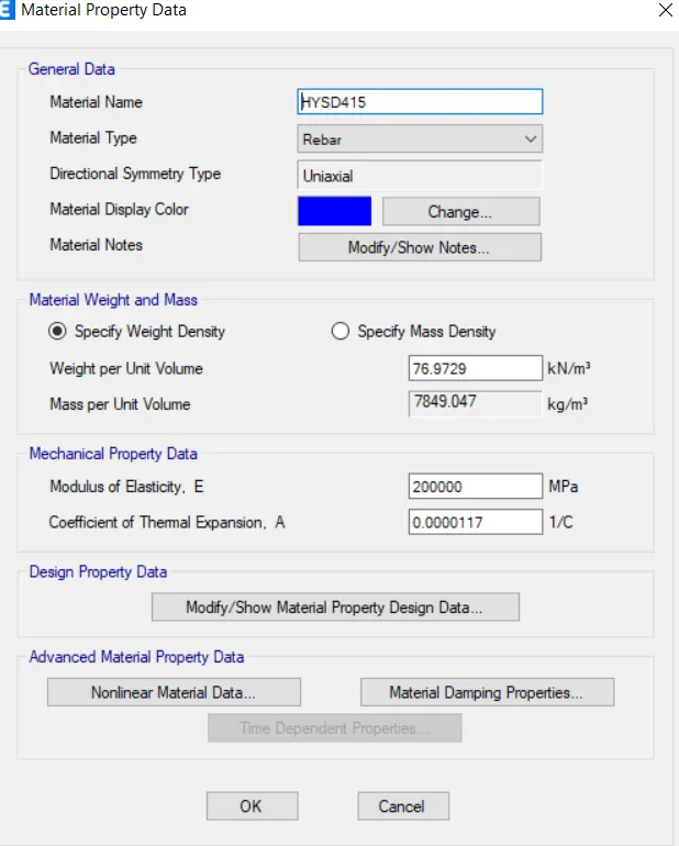
Now,go to section properties and sizes for beam ,column and slab are to be entered.
beam size = 300*400
column size = 400*400
slab size = 150mm
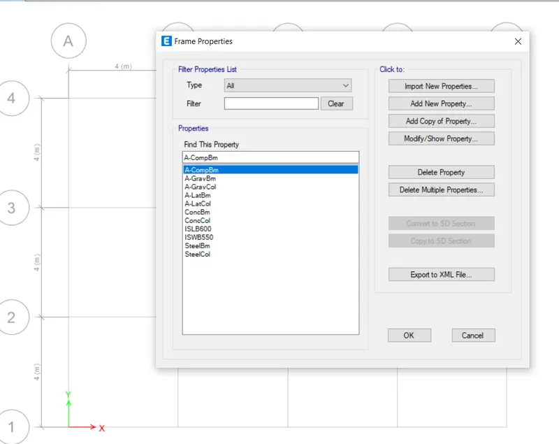
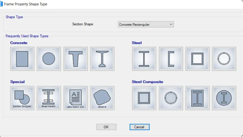
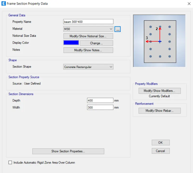
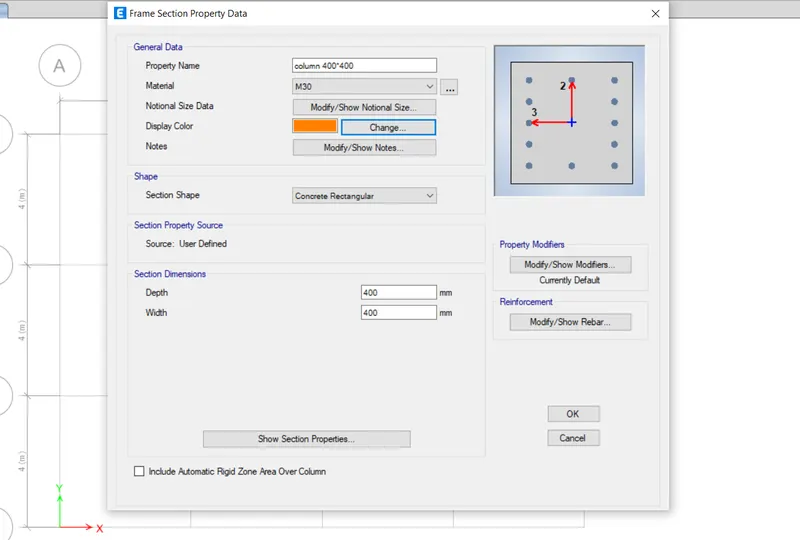
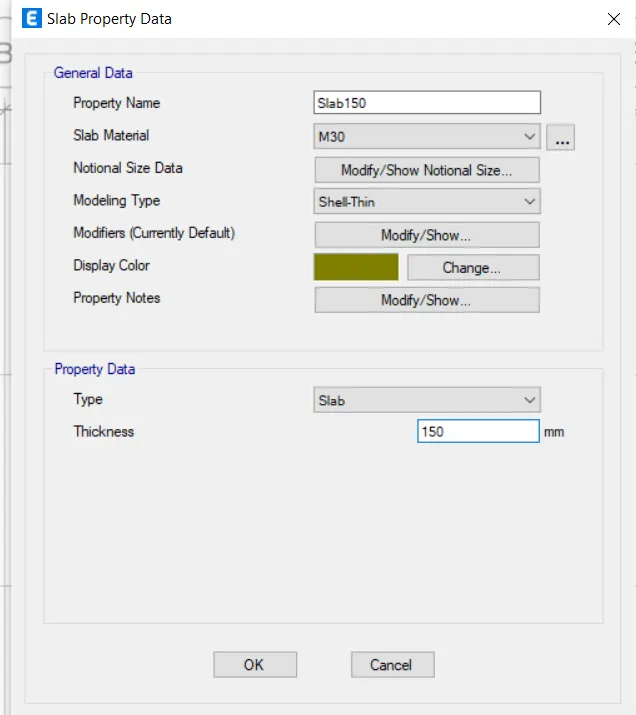
Now, click on define and go to load patterns , now a pop-up comes as shown below.
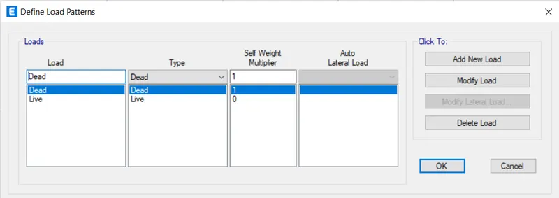
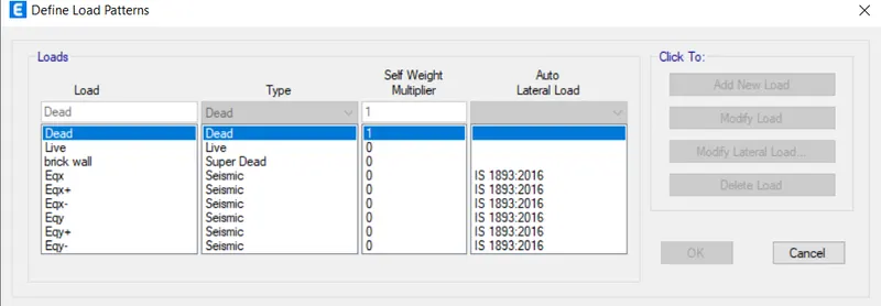
Now ,the required loads are entered s shown below
Now,to draw colums ,click on quick draw column and locate at the column at each grid.
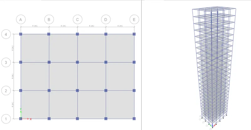
After completion check in 3D view as shown below.
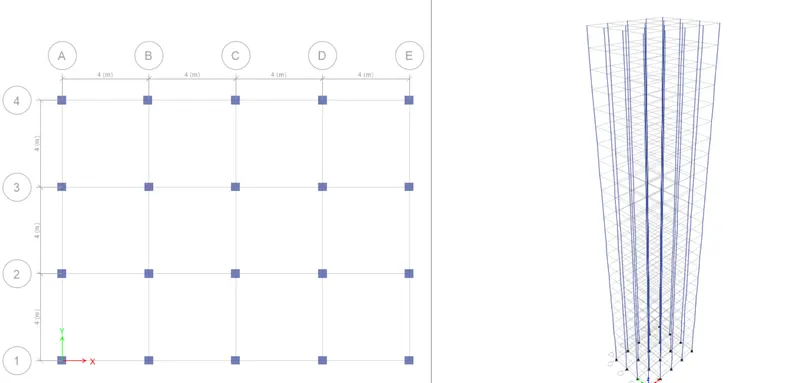
Similarly ,we need to place beams and slabs using quick draw beam and quick draw floor icons.
After completion of it,it will be as shown below.
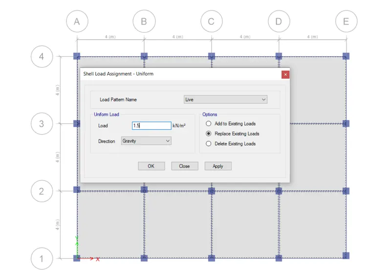
Now ,we need to assign loads. At first assign the loads to roof slab,select all the slabs and click on
assign option and select the load as live and of value 1.5kN/m2.
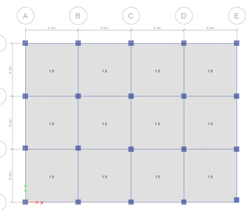
Now ,we can see the assiged load as shown below.
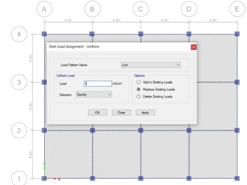
All the other floors are assigned with a live load of 3KN/m2.
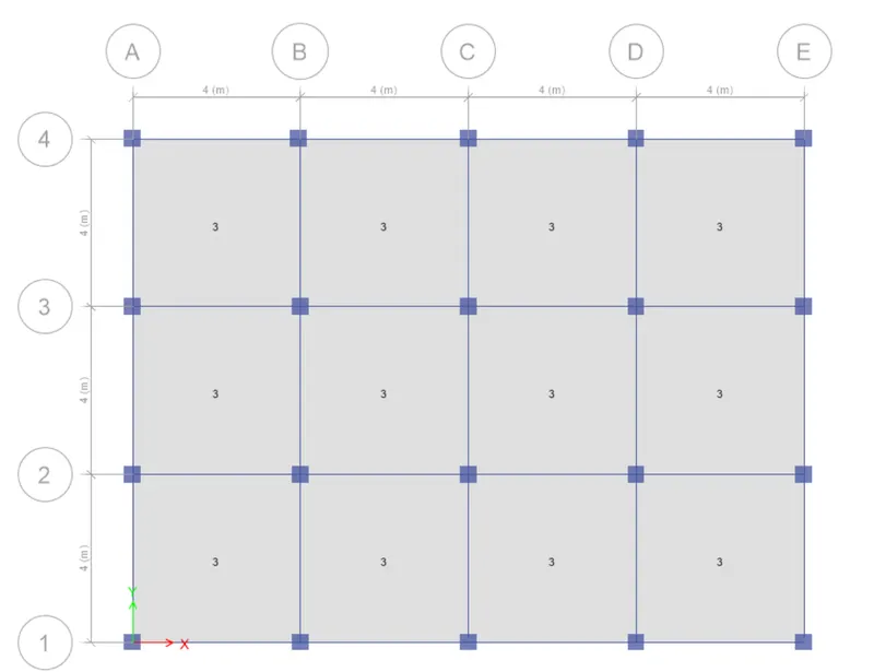
Now,select all the beams and assign a load of 10 KN/m2 as shown below.
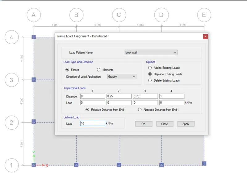
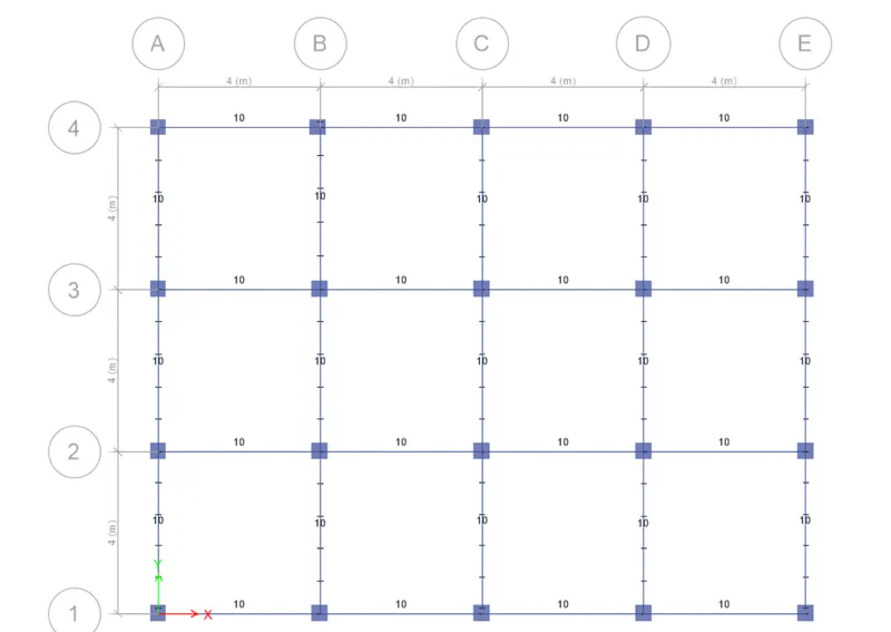
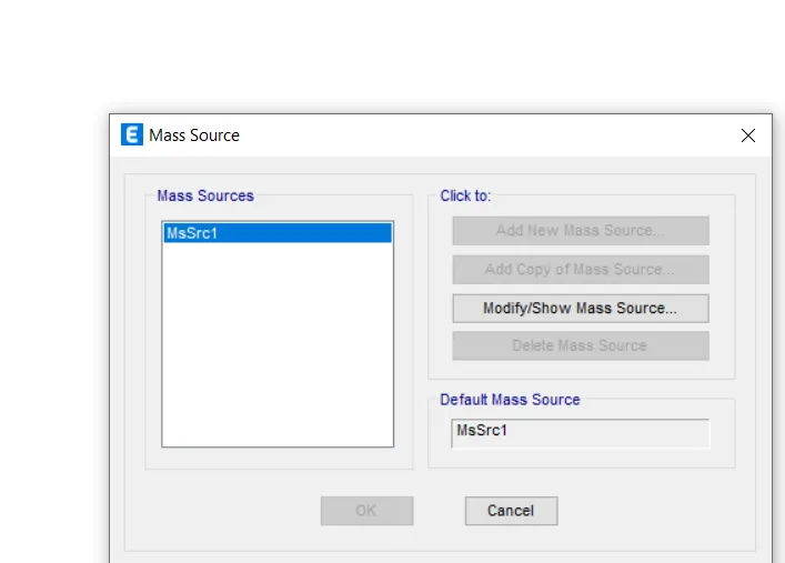
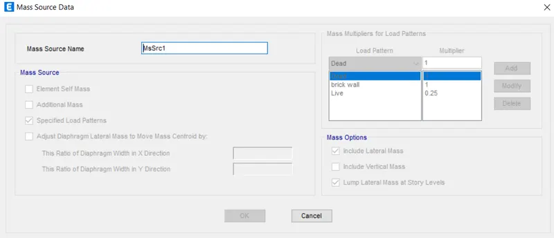
Now ,go to define,and then select mass source and assign as shown.
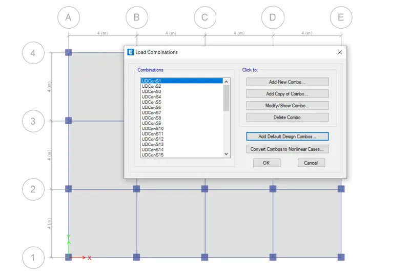
Now,go to load combination and select modify, a list of combinations appears as shown below.
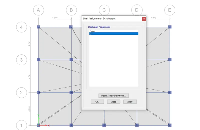
Now, go to assign and then to shells and then click on diaphragm and assign it as D1 as shown below.
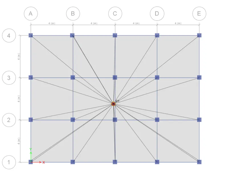
Now, go to analyse and check model
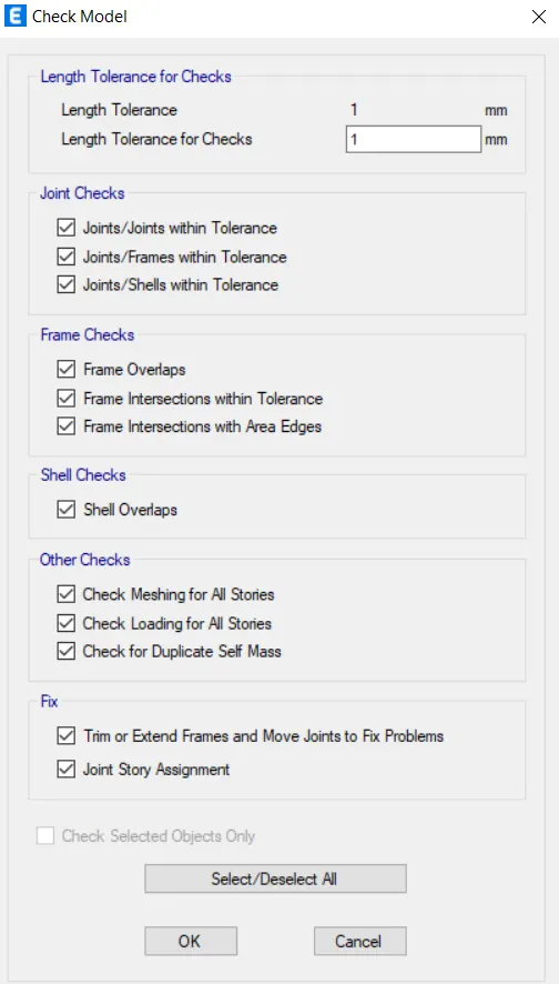
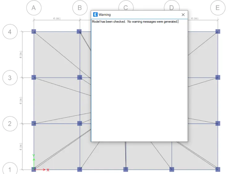
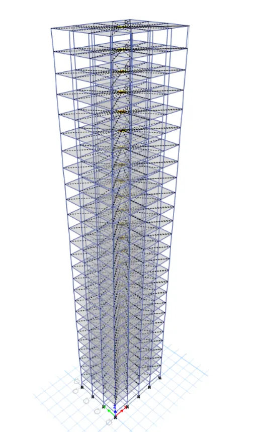
As shown above,there are no warnings and the final structure looks as shown below after the application of loads.
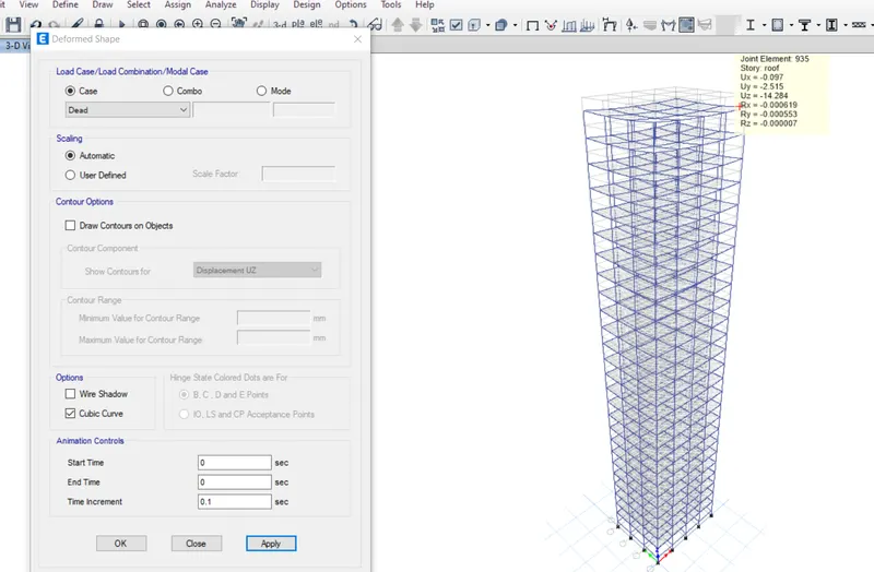
following is the deformed shape of the structure and when we click on any joint we can see all its data as shown below.
Now,go to display and select show tables and then click on mass participating ratios as shown below.
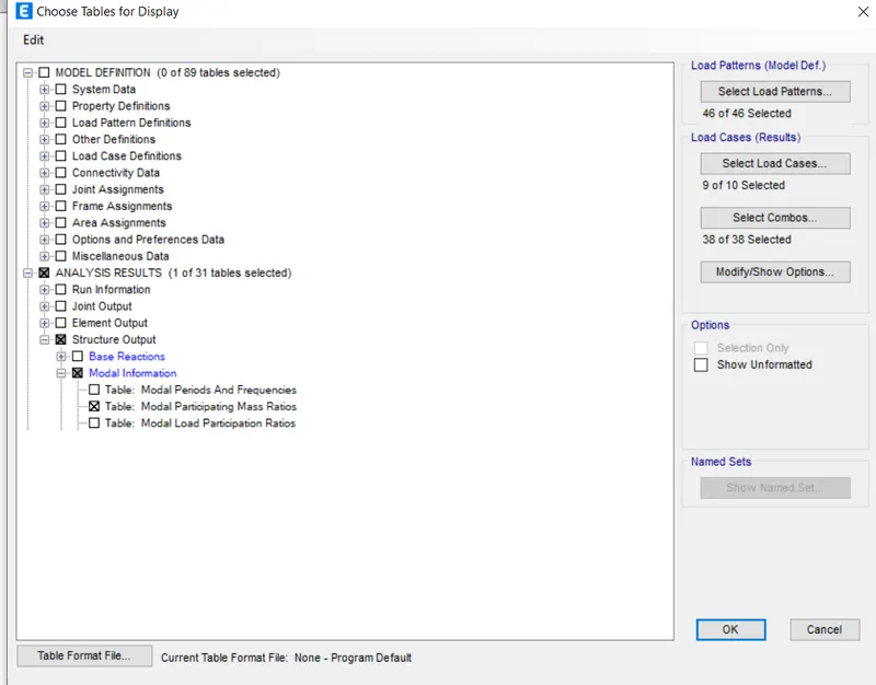
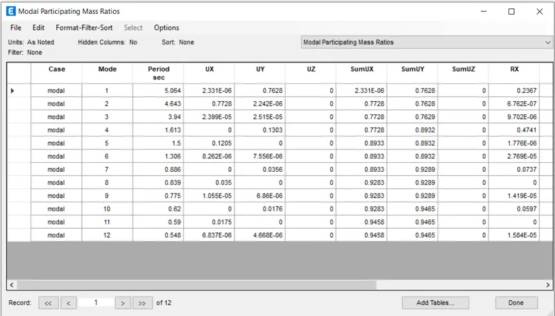
We can now see the modal participating mass ratios