Identification of Cracks
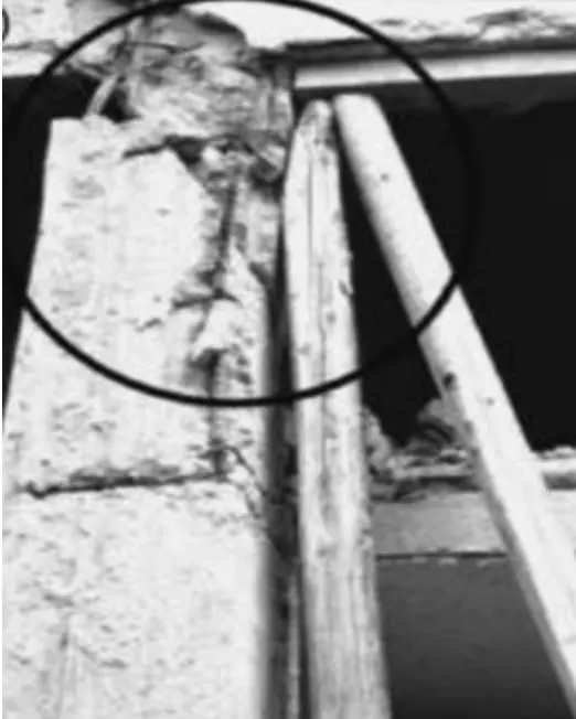
1.a: This image shows a damage at the Beam-column joint. We can see it very clearly that the part
of beam is damaged more. The main cause for this damage is that, the provision of
insufficient cover to the beam from the reinforcement. Another cause for this damage
is the insufficient vibration of concrete as there is a chance of obstruction to the process of
vibration by the reinforcement. This is clearly a"Flexural damage". These type of effects can be seen
at the bottom flange of the beam. There is a chance that bottom bars may buckle and further
rupture under the large cyclic excrusions of strain at he open crack . Providing a proper cover at
the joint is the repair that can be done for this type of damage.
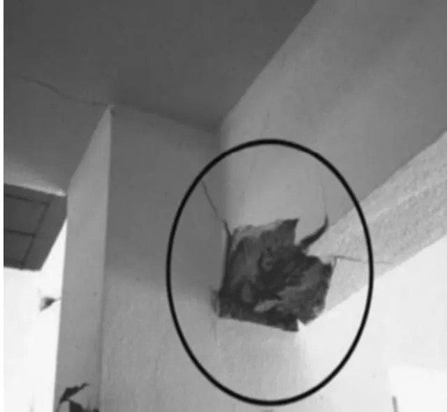
1.b: This image is also a damage. We can clearly observe the pullout of beam bars from a narrow corner column
and this is mainly due to the bars of beam with insufficient anchorage in a joint ,that may got pulled out when
an earthquake occurs. Improper anchorage and the failure of bond result in development of a crack at the end
section and may extend through the depth of the beam.The insufficient anchorage provided to beams obstructs the
formation of plastic hinge at the ends of beams. These type of damages can be repaired but, the loss of anchorage
in beam bars can not be treated easily.
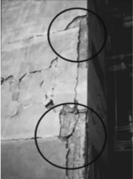
1.c: This image is also a damage. We can clearly observe that there are wide cracks in slab orthogonal
to the beam at the beam-column connection.These cracks may extend ,travel a good distance and may also
join with the other cracks extended at right angles from the parallel beams. This shows the complete participation
of slab in the flexural action with the bars of it being parallel to beams.This can be only repaired temporarily and in
the long run this damage causes harm and may turn into a failure.
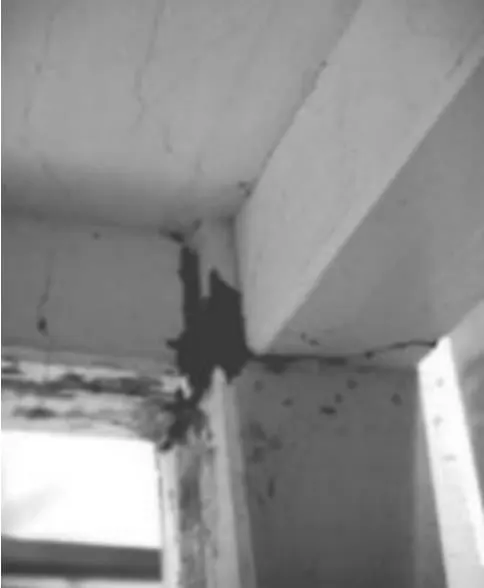
2.a: It can be clearly observed that the image shows a failure of column due to buckling. The column
should be the long one. The failure happened because, the column could not resist the buckling
load though the beams are provided at intermediate levels. These type of failures can be identified easily
as they include a visible horizontal crack and loss of concrete cover,bar buckling,opening of stirrups and
concrete disintegration.
In most of the cases, buckling is observed at the midpoint of the column, as the
Bending moment is maximum and the shear force is zero. To prevent these failures, it is
necessary to provide reinforcement in such a way that the lapping of all the reinforcement bars
in a single column not meeting at the same point. Providing alternate bars for lapping of joints is
better.
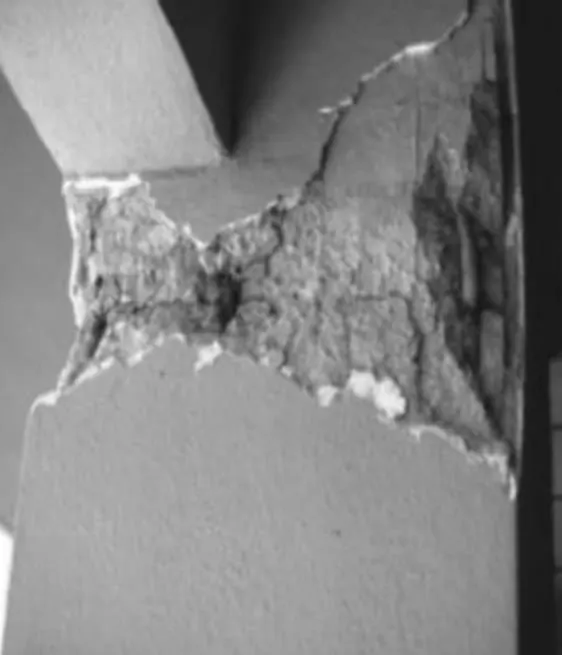
2.b: The image shows a failure caused due to Shear. It is well known that, high shear forces are
attracted by the columns that are short. This type of unwanted deformation caused is known as
“SHORT COLUMN EFFECT”. This type of failure mainly occurs at the open ground floor levels and
is frequently observed during Earthquakes. These type of effects must be considered in the design
stage.
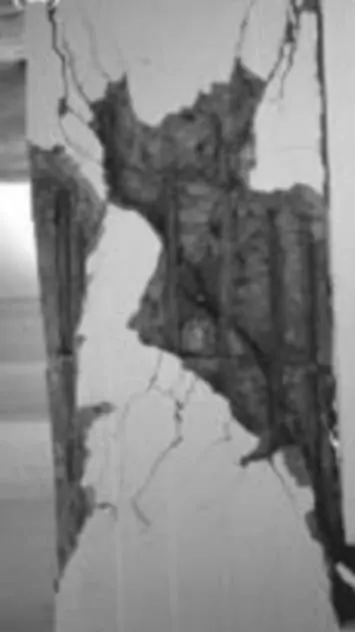
2.c: The image shows that it is a failure at beam- column joint. This is clearly a shear failure of the column. The indication
of shear failure is a diagonal crack or a failure zone. Stirrups intersected by the diagonal failure may open or may
break. Disintegration of concrete takesplace along the diagonal failure zone or can also takeplace across the core within
the reinforcement. This type of failure leads to the loss of lateral stiffness and column strength, which clearly indicates a
brittle failure.