Modeling Tesla Model S with Matlab and Simulink.
- 1) AIM
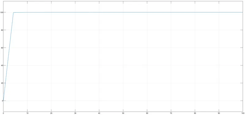
- To establish the mathematical model of electric car (Tesla model S) based on a DC motor rather than a 3 phase induction motor and try to design a Simulink model with the complete dynamics and to establish control over the speed of the car using PID speed control. Tune the PID in such a way that top speed of 100 km/hr is reached in 4 sec
- 2) Theory, Assumptions,Inputs:
- Modeling is the process of representing system behavior using mathematical equations and relations. The approach followed is the white box modeling approach where the relationship are established using mathematical formulae .
- Tesla uses an induction motor but here a DC motor is used
- Transfer function in control systems is the functional relationship between the output signal of a control system and the input signal, for all possible input values. A block diagram is a visualization of the control system where the block represents the transfer function, and arrows which represent the various input and output signals. In complex systems, the time domain is converted to the Laplace domain. For any system, an input that is is dependant variable of time say for example x(t) when converted to Laplace domain L[x(t)] becomes X(S).
- Say the input is already in the Laplace domain and is represented by X(S) and output is represented by Y(S).
- Then the transfer function G(S)= Y(S)/X(S)
-
Vehicle parameters - Tesla to calculate tractive effort and vehicle dynamics
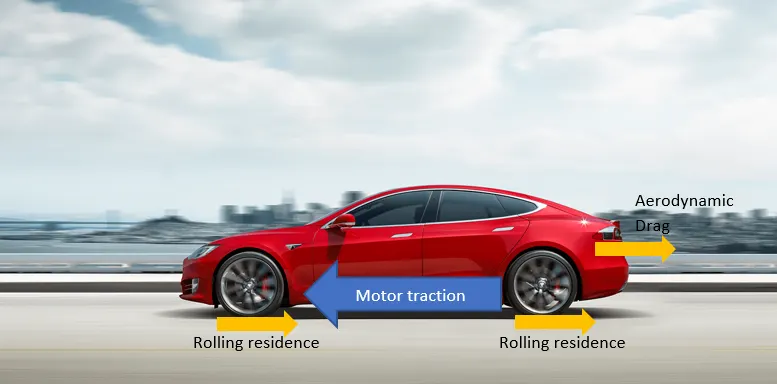
- Traction force: energy conversion from electric to mechanical through motorand wheels.
- Aerodynamic drag: air displacement when moving or due to wind gusts.
- Rolling resistance: tyre deformation on the ground due to the weight of the car.
- Car Inertia: inherent property of masses to resist changes in motion
- Force due to rolling resistance ,Frr= Urr*m*g where Urr is Coefficient of rolling resistance,m is sum of kerb weight and payload, g is accelaration due to gravity
- Force due to aerodynamic drag,Fa= 1/2*p*A*V^2, p is Air density, A is Frontal area,V is velocity of air stream flowing around the body
- Force due to hill climb,Fhc=m*g*sin(psi),m is sum of kerb weight and payload, g is accelaration due to gravity,psi is angle in radians
- Total Force= Frr+Fa+Fhc
- According to the 2nd Law of Newton, the sum of all external forces acting on an object is equal to its mass multiplied by its acceleration. This can be written:
F=ma - When the body is accelarating,G*(T/r)=Urr*m*g+1/2*p*A*V^2+(m*+I*(G^2/nG*r^2))*(dv/dt),G gear ration
- a) Weight: 2108 kg
-
b) Drag coefficient: 0.24
-
c) Frontal Area:2.34 m²
-
d) Power: 460 HP/343kW ,8600 RPM
-
e) Torque:600Nm
-
f) Wheel Rolling resistance Coefficient on asphalt: 0.02
- The below image represents the forces acting on the car:
- Here after substituting all values, while assuming a 70% motor efficiency
- 0.7 ∗ 40.5t − 413 − 0.3381v=2108 ∗ a
-
The Tesla Model S Battery
-
a) The model S battery is assembled with 7104 18650 Lithium-ion cells.
-
b) 16 Modules wired in series each containing 6 groups of 74 cells wired in parallel themselves wired in series within the module.
-
c) Its total capacity is 85 kWh and it weighs 540kg.
-
d) Each NCR18650B cell has an average capacity of 3300 mah, a nominal voltage of 3.6V so about 11.9Wh.
-
e) Their maximum voltage is 4.2V and they are discharged at 2.5V.
- f) In a circuit mounted in series, the Voltage of the circuit is the sum of the Voltages of its components but the current remains constant.
- In a circuit mounted in parallel, the Voltage of the circuit is the same throughout but the current is the sum of the current going through all its components mounted in parallel.
- Thus, we can calculate the nominal battery voltage:
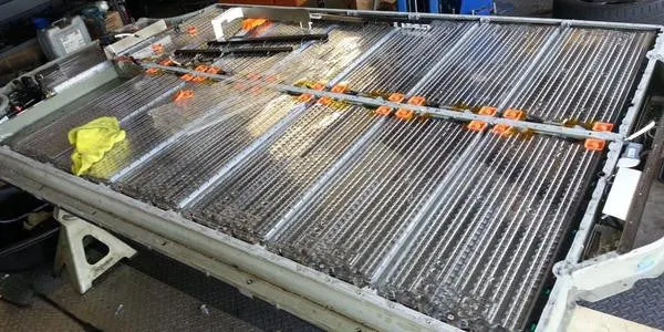
V can be established as V= 3.6 ∗ 16 ∗ 6 = 346 V - Below is the image of Model S battery pack
-
- Mathematical model of DC brushless motor used:
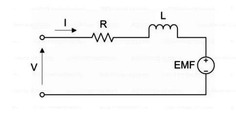
- Voltage across resistor= I*R
- Voltage across inductor =L(dI(t)/dt)
- Applying kirchoff voltage law in the loop V=I(t)+L*dI(t)/dt+E(t)
- Torque developed by Motor,T=Kt*I where Kt is the motor constant
- if w is rotational speed in rad/s then,back emf Eb=Ke*w where Keis the back emf constant
- Hence V(t)=I(t)*R+LdI(t)/dt+Kb*w(s)
- The above equation is transformed into Laplace domain: V(S)=R*I(S)+SLI(S)+Kew(S)--(1)
- The same can be applied to torque equation,T(S)=Kt*I(S)--(2)
- From equation (1),I(S)=V(S)-Ke*w(S)/SL+R
- Torque as a function of Voltage Input and rotational velocity:T(S)=Kt*(V(S)-Ke*w(S)/SL+R)
- The data for DC motor below are put into equation:
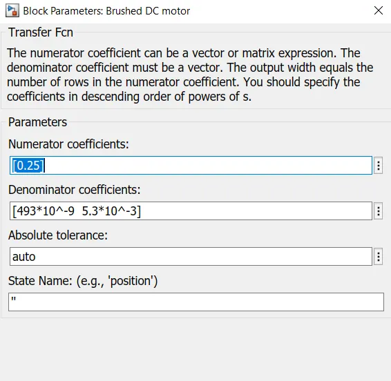
- R = 5.3 *10^−3 Ohm,L = 493 *10^−9 H, Ke = 0.12 Vs/rad,Kt = 0.25 Nm/A
- T(S)=0.25*[V(S)-0.12*w(S)/493*10^-9*S+5.3*10^-3
- 3) PROCEDURE SIMULINK MODEL
-
Initially open a new blank model and create a constant block and set its value to 346V
-
This represents the input voltage from the battery.
-
In a circuit mounted in parallel, the Voltage of the circuit is the same throughout but the current is the sum of the current going through all its components mounted in parallel.
-
Thus, we can calculate the nominal battery voltage: V can be established as V= 3.6 ∗ 16 ∗ 6 = 346 V
-
Secondly we will develop a Transfer Function block which relates to the output which is Torque and Input which is Voltage.
-
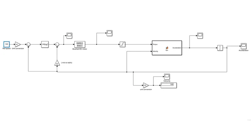
Inorder to form a closed loop so as to facilitate reference tracking a sum block is added. The closed loop includes the trasnfer function which represents . Torque produced from the Transfer function as output and the battery voltage as input as shown below:
-
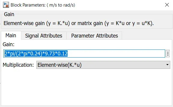
A gain block is used to convert a linear velocity from m/s to angular velocity of wheel in rad/s.
-
A matlab function block to calculate accelaration by taking velocity and torque as input parameters.
-
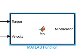
- Inside the matlab function block the scripting is done
-
function Accelaration = fcn(Torque,Velocity) Accelaration= (40*Torque*0.6-413-0.3381*Velocity^2)/2108; -
An integrator block is used to calculate the velocity from acceleration in the Laplace Domain
-
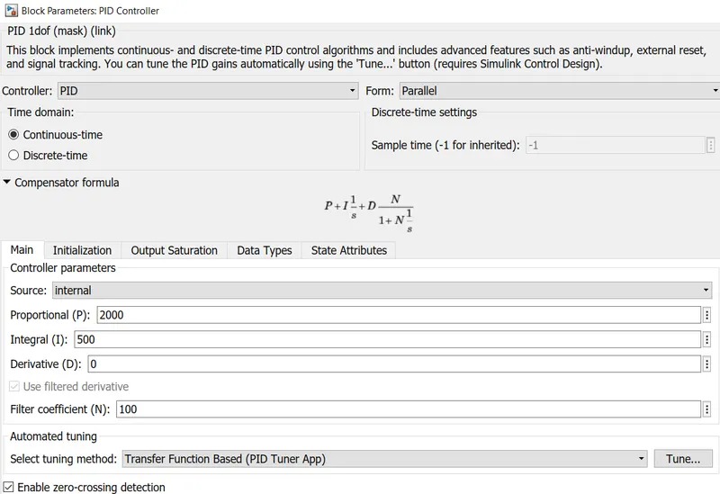
A PID Controller is added error term block used for actuation to optimize the Dynamics response of the system.
-
The PID is autotuned to obtain the desired performance
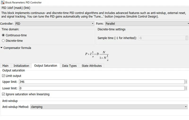
- A saturation block is used to restrict the torque value to a limit
-
Post this the model input is modified where the input Voltage parameter into a input speed parameter in Km/h, for this a conversion block is used
-
Hence the entire Simulink Model is shown below:
- 4) Results and Inference:
- Velocity of 100 km/hr in 4 sec is acheived below
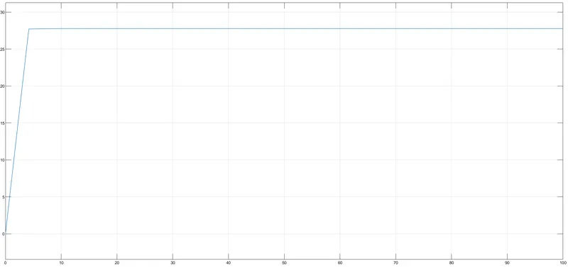
- There are many ways to tune a PID. In this project there is a saturation of actuating signal hence anti clamping was used.
- 5) References
- Devanshay Goelcan you please share the file if possible i am not able to get the exact ans