Meshing the Geometrical Components using FEA Tool
Aim - To check for the geometrical errors and mesh with the given element Quality criteria for Practise, Clip Repair & Mounting Bracket using FEA tool HYPER-MESH.
Procedure -
Step I - Import the geometry with .hm extension from the system.
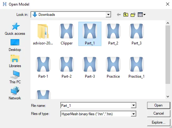
fig - Importing Geometry
Step II - Select parent geometry and go for geometry check.
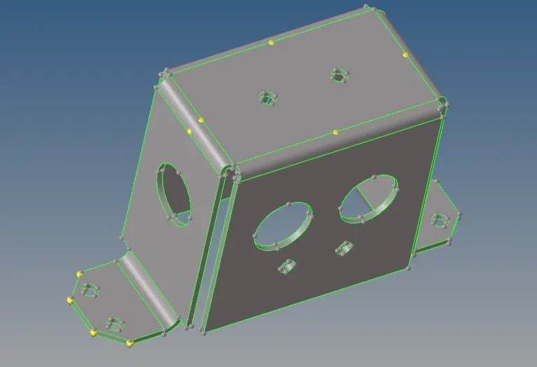
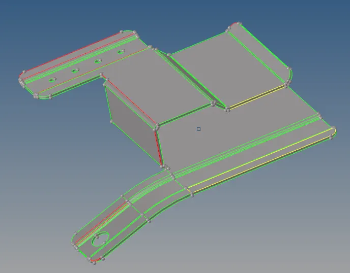
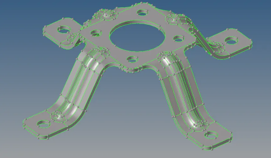
Imported geometry have some geometrical error which need to be cleared using varous tools available in the panel like quick edit, line edit, temp nodes, etc in the geometry tab.
1. In the part I there were temp. nodes which has been cleared using the temp node tool.
2. In the part II there was some surface missing from the geometry and some unwanted surfaces which has been cleared using quick edit tool and delete entity tool.
3. In the part III there was no error found so the model is already error free.
Step III - Midsurface Extraction
After cleaning the geometry midsurfaces for all the three models is extracted usng the auto and manual midsurface extraction method using midsurface tool. Apart some midusrfaces are extracted manually using offset tool to grab the features appropriately.
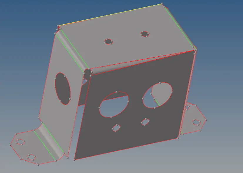
fig - Part I midsurface
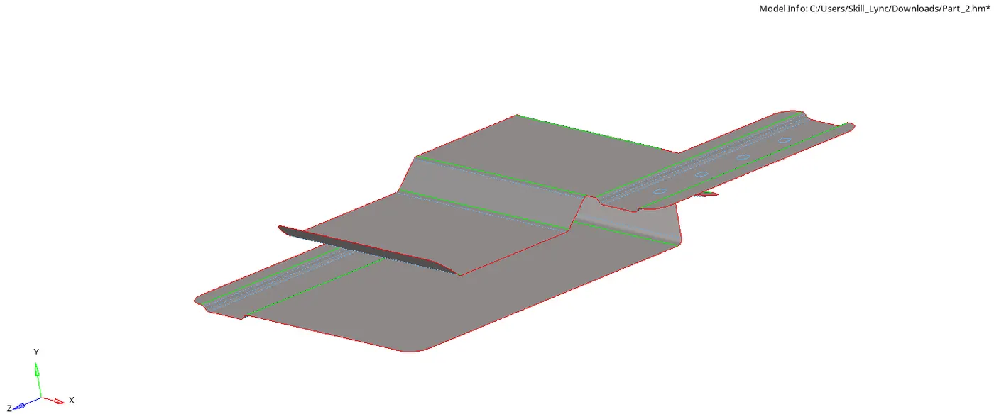
fig - Part II midsurface
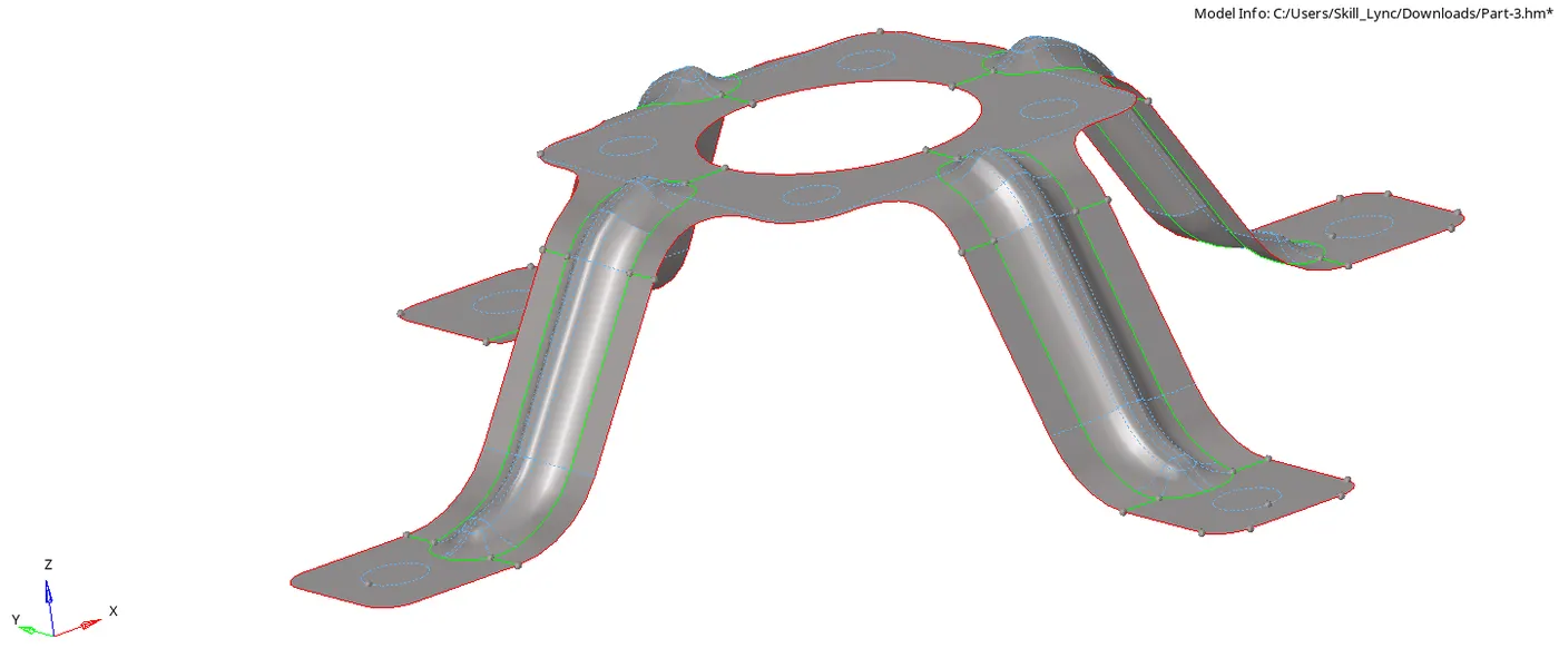
fig - Part III midsurface
After extracting the midsurface for part I and part II there is still some geomerical errors present in the model which is shown below,
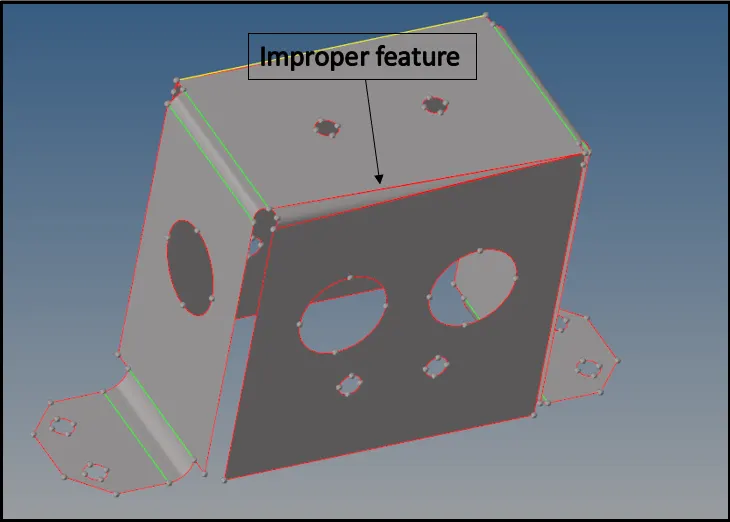
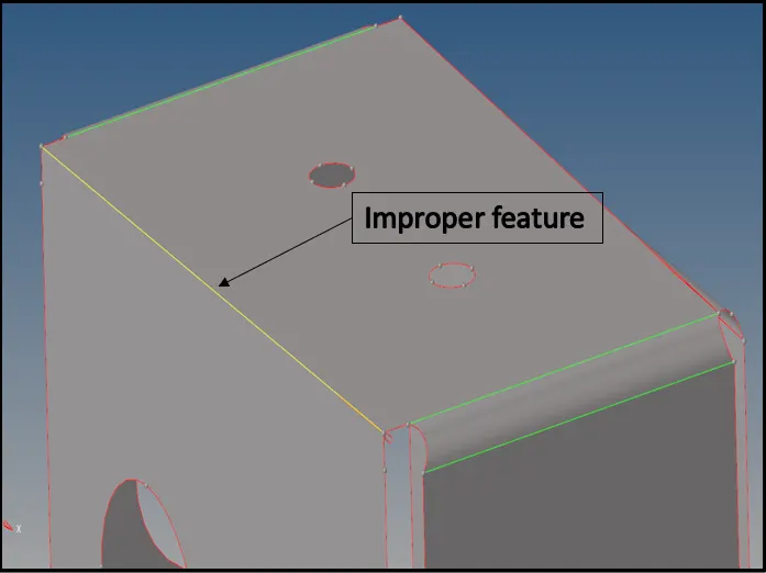
fig - Part I improper feature capture feature acpture after auto mid extraction
This feature is been clered by deleting the entity and adding new entity instead using the offset tool and duplicating the entity to the middle surface from the parent geometry.
Step IV - Defeaturing the features
After extraxtion of midsurface some features were defeature from the surface of the midsurfaces of all the three models using quick edit panel with the help of toggle command.
Holes diameter less than 5-6 mm are neglected to capture the mesh accurately in those regiosns.
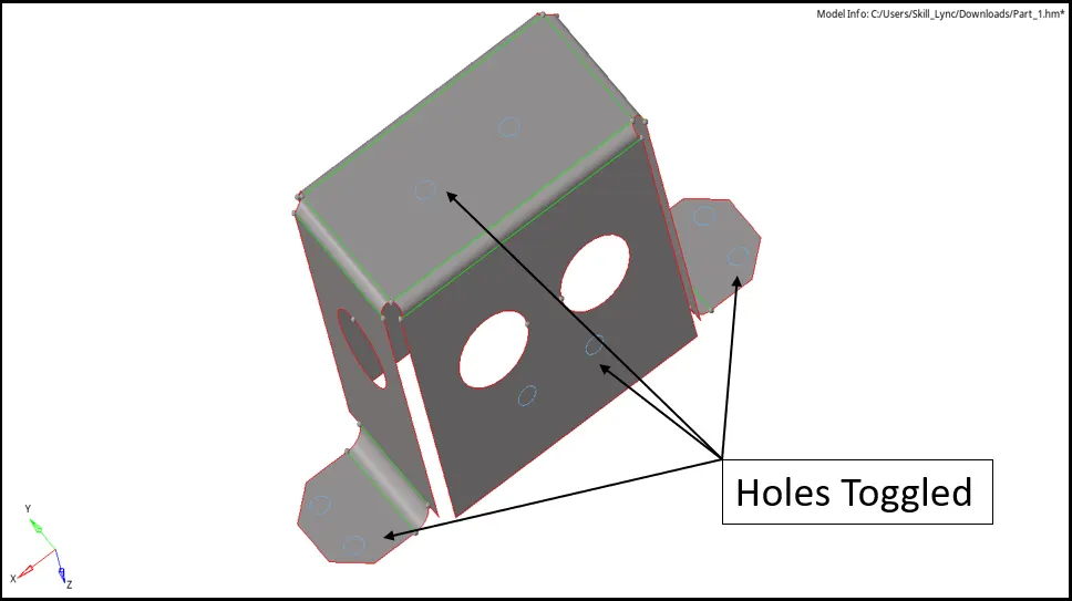
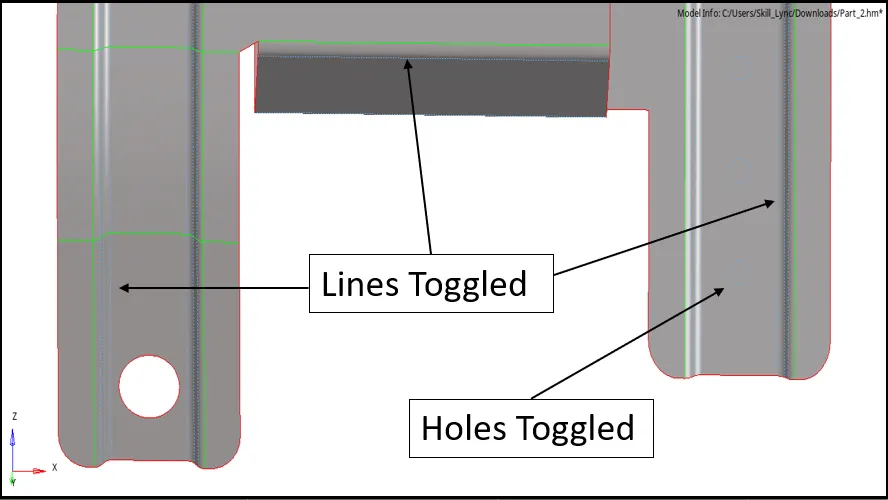
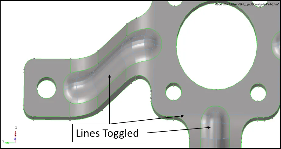
Step V - Meshing the midsurfaces
After defeaturing the features feom the midsurface, meshing is done. For meshing the components under 2D tab there is Automesh tool available to mesh the geometry. All the three geomerty is meshed as shown below,
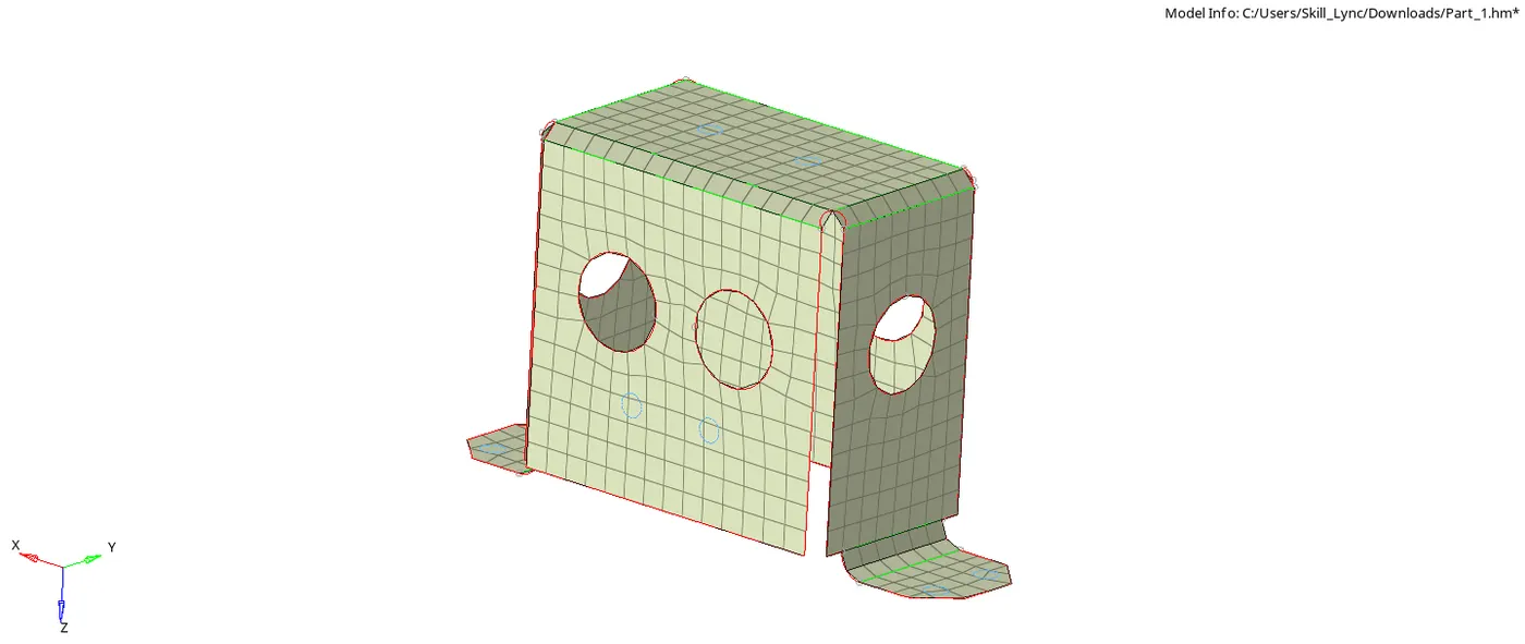
Fig - Part I Meshed Midsurface
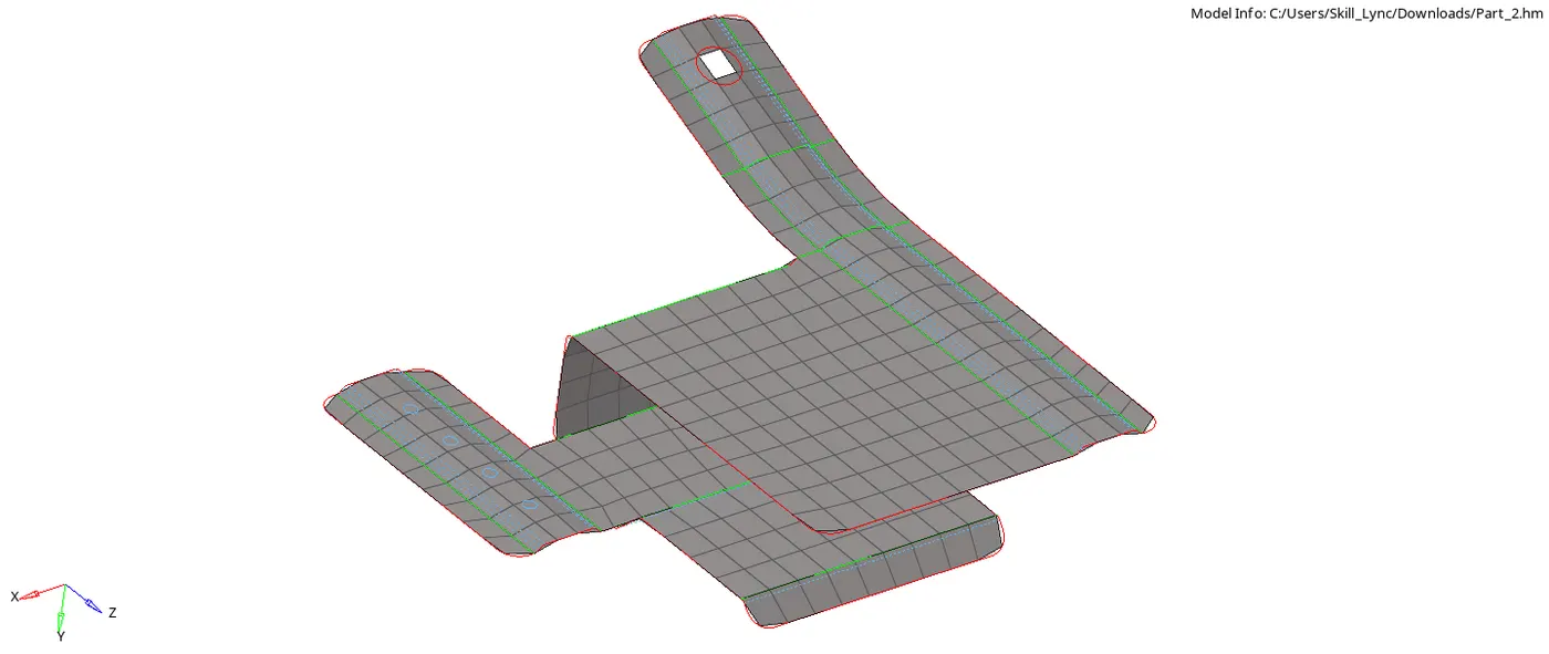
Fig - Part II Meshed Midsurface
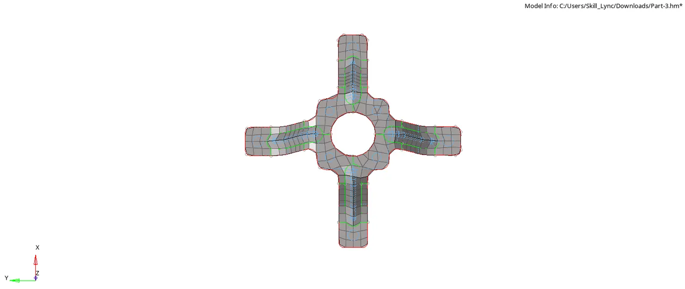
Fig - Part III Meshed Midsurface
Step VI - Element Quality Check
After meshing the midsurface next step was to check the elements for given quality criteria
Quality Criteria :
Target Length - 5 mm
Min Length - 3.5 mm
Max Lenth - 7 mm
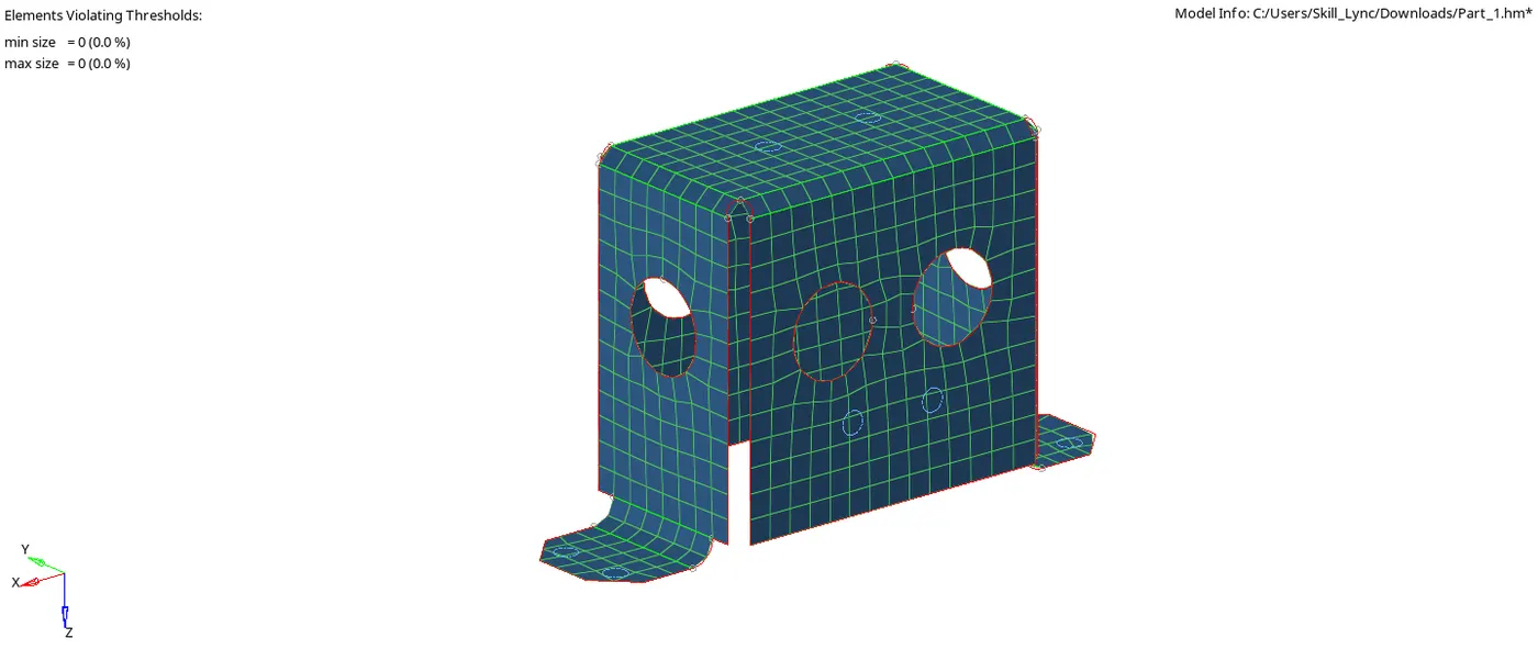
Fig - Part I Element Quality Check
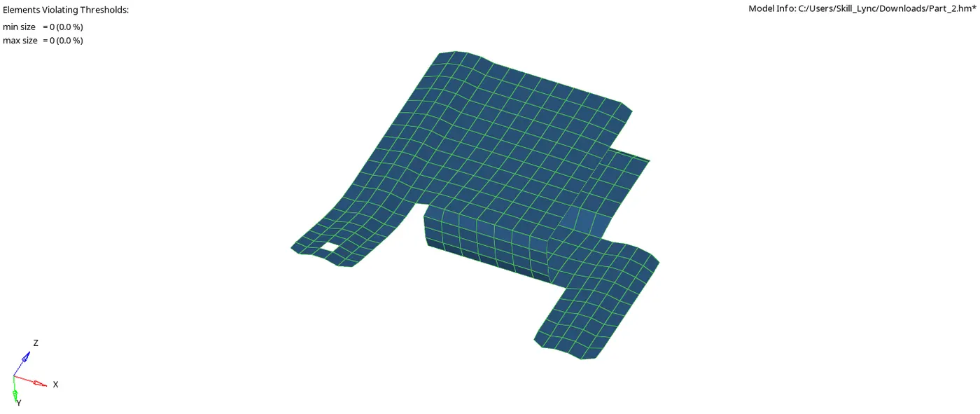
Fig - Part II Element Quality Check
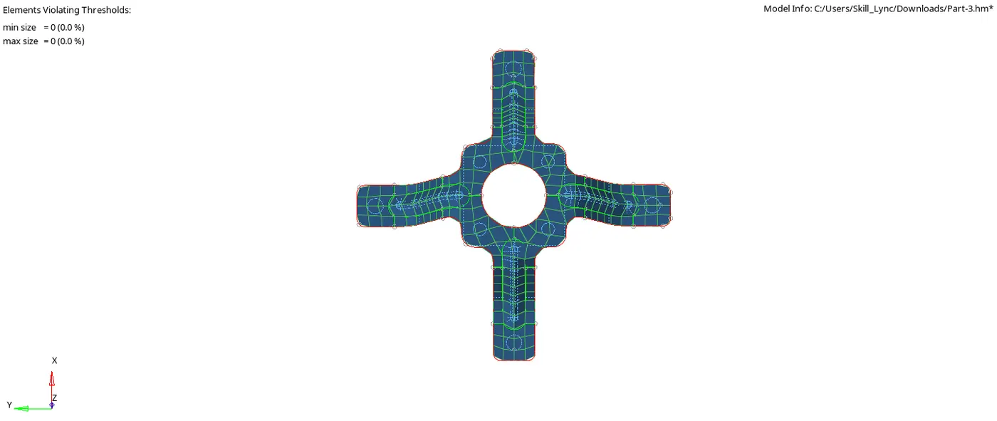
Fig - Part III Element Quality Check
Some element which were failing for the quality criteria were cleared using the tools like split, combine and some of quality cleanup tools like placing the node, optimize element and smooth.
Step VI - Thickness Assignment
After checking the geometry's for quality check next stepis to assign the property to the geometry's and assign appropriate thickess.
Property is assigned to the geometty from the model browser and thickness is assign under property using thickness option. Respective part thickness is assigned by measuring the thickness from the paent geomerty.
Thckiness -
Part I : 2 mm
Part II : 0.91 mm
Part III : 1.8 mm
After this under the visualization panel detailed 2D View option is selected.
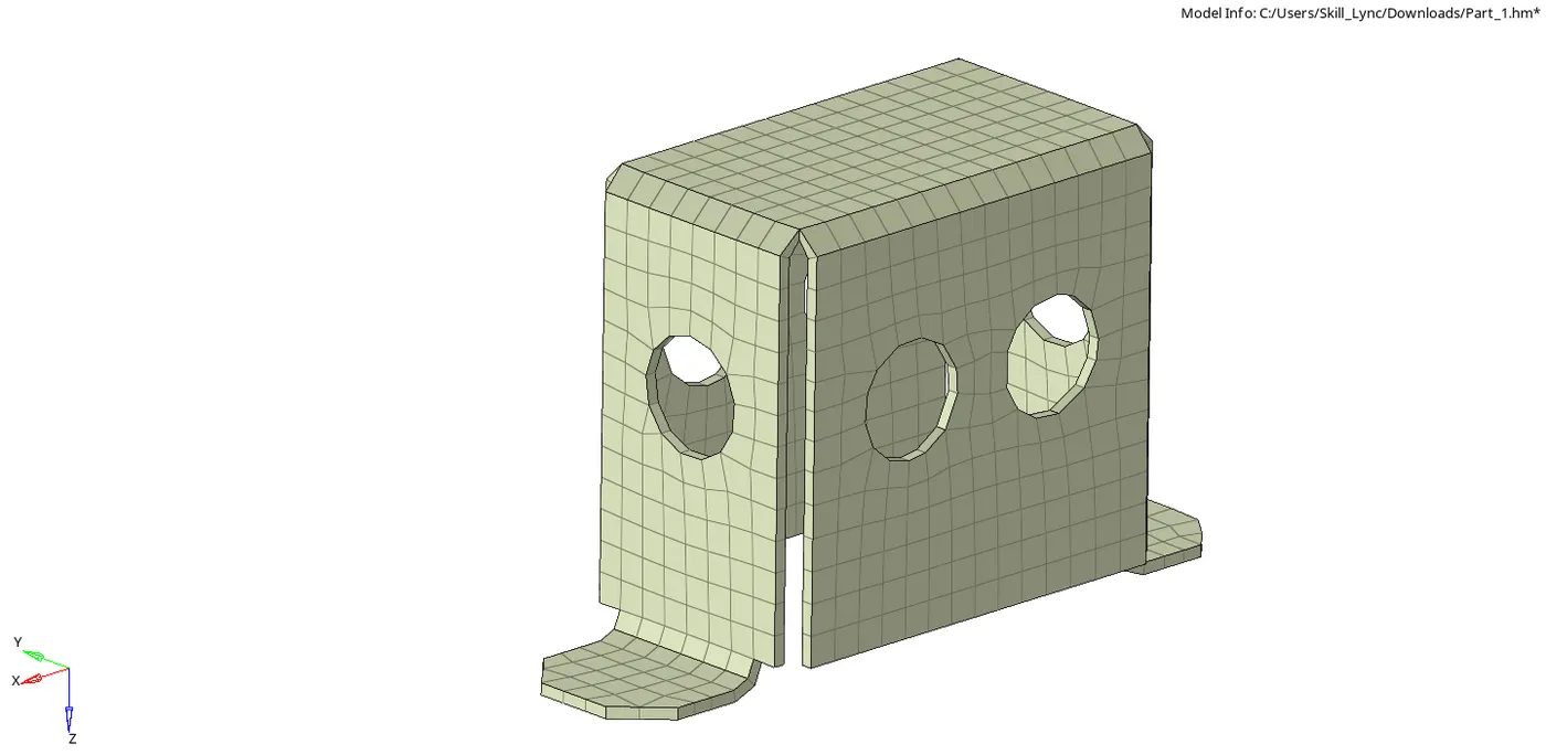
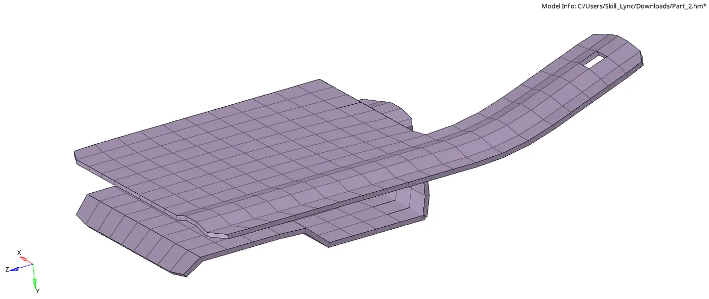
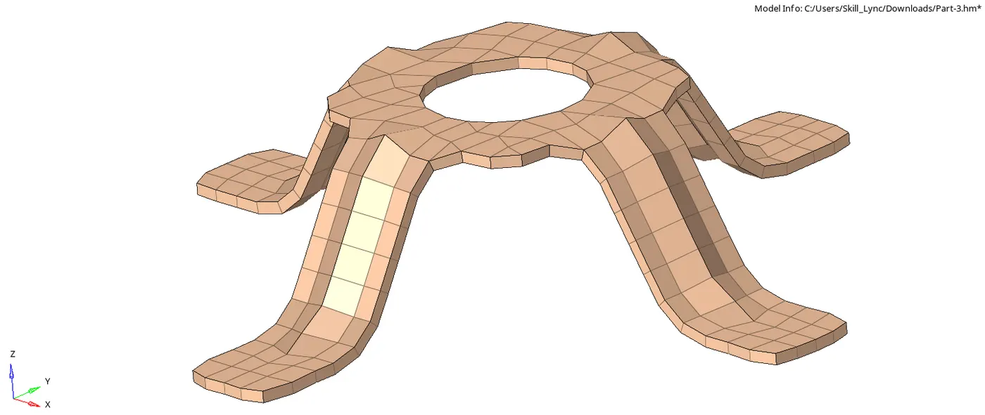
Fig - Detailed 2D View of the models
Learning Outcome:
1. HYPER-MESH Software Basic
2. HYPER-MESH Panel
3. FEA Tool HYPER-MESH Shortcut Keys
F2 - Delete, F3 - Replace, F7 - Allign, F11 - Quick Edit, F12 - Automesh,, etc.
Conclusion :
Sucessfully meshed the gremetrical components and necessarry correction are made to repair the mesh quality error.