MESHING THE AUTOMOTIVE HOOD using the FEA Tool ANSA
Aim - To check for the geometrical errors and mesh with the given element Quality criteria using FEA Tool ANSA.
Procedure -
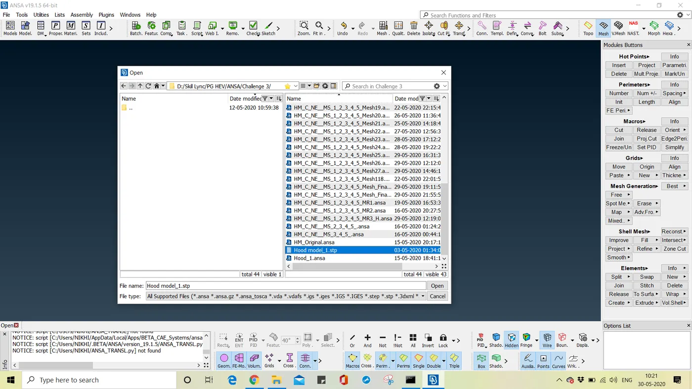
Step I - Import the geometry i.e, .step file (extension)using the file tab in the ANSA window.
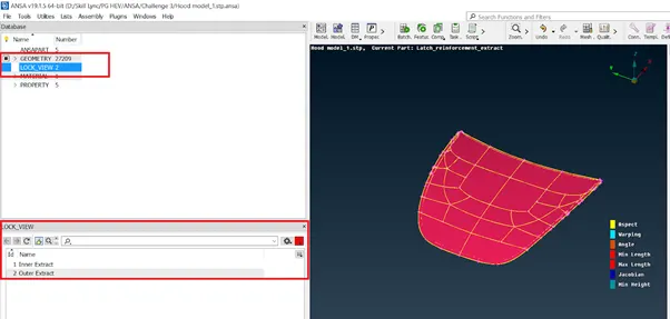
Step II - After importing the geometry, switching to the topo module. In the topo module under the list tab, we open the properties list of the geometry. From there we separate all the property IDs and store them in different lock views one by one.
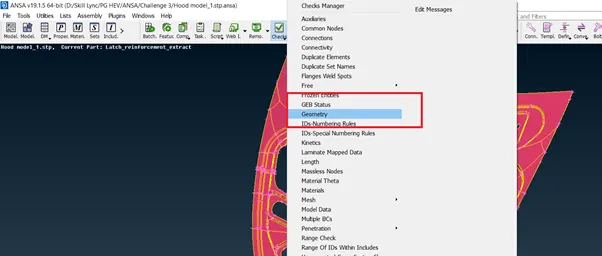
Step III - Select any lock view and go for geometry check in the tools tab.
After checking for geometry, we get the following errors in the geometry. There are many needles face errors in the geometry. This needle face error is nothing but the unwanted faces in the geometry which needs to be cleaned up.
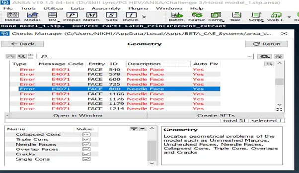
Here I select error entity Id no - 800 and go for show only using the right click on that error.
As I click to show only needle face highlight in the window. In the Topo Module, under the cons, there is an option to release the cons. This release will release the cons which are automatically pasted.
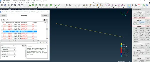
Fig - Needle Face Error Id no 800
After release there forms a crack at the same location where this con was automatically pasted which can be seen below,
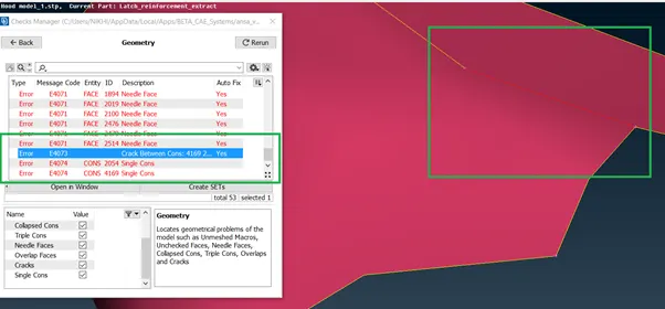
Fig - Geometry after performing release function
To remove this crack error, we perform topo on this con and after performing the topo this error gets fixed as shown below,
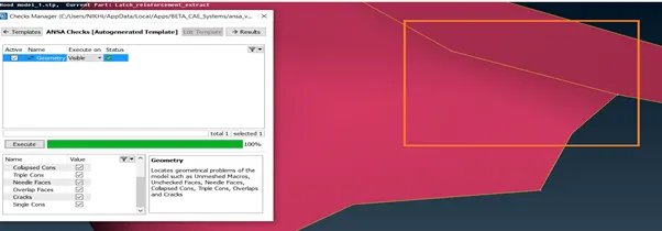
Fig - Geometry after performing Topo
Similarly, all the errors in the geometry are fixed and at last, there is no error after performing a geometry check-up.
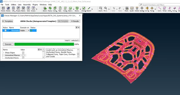
Fig - Zero Error after the geometry cleaned up
After geometry clean-up, we check for the thickness measurement of the various components and extract the mi surface using the offset option
Step IV - Extracts mid surfaces of the components using offset command.
Select any one original component to let's say, Latch - 1 with measuring the thickness of the component across various sections as 1.20 mm mi surface is extracted using offset command at a distance of -0.6mm from the top surface
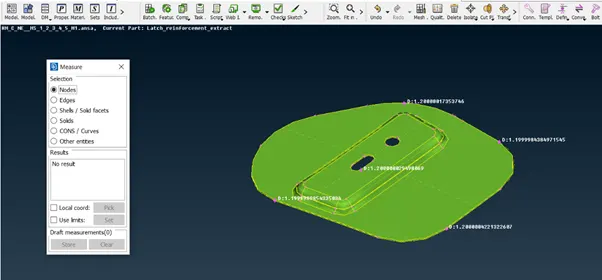
Fig - Measurement of thickness - 1.20 mm
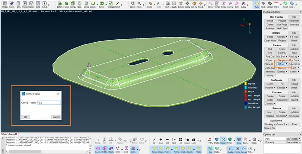
Fig - Mid Surface extract using offset command at -0.6mm
After extracting the mid surfaces each component had been assigned a separate new PID and respective thickness.
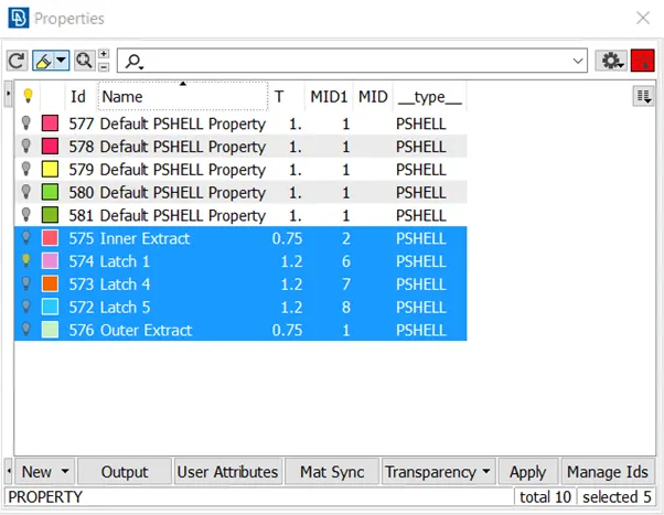
Fig - New PID Assignment with a respective thickness
Step V - Meshing the geometry using Mesh Module
Before meshing the modules, we assign perimeter length, mesh parameter, and quality criteria as below,
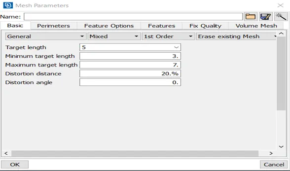
Fig - Mesh Parameters
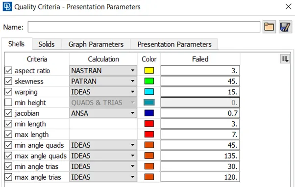
Fig - Quality Criteria
After assigning the parameter we select the latch 1 component and make the cuts as below to obtain a good mesh flow of the elements as below,
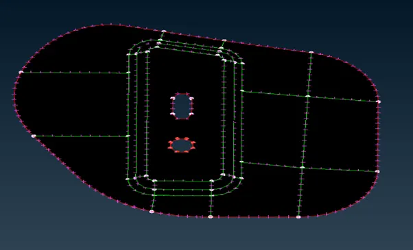
Fig - Cuts made to obtain good mesh flow
After making the cut geometry is mesh using the best command in mesh generation tool and with the help of various others commands like reconstruction, smooth, paste, join, etc and mesh is obtained as shown below,
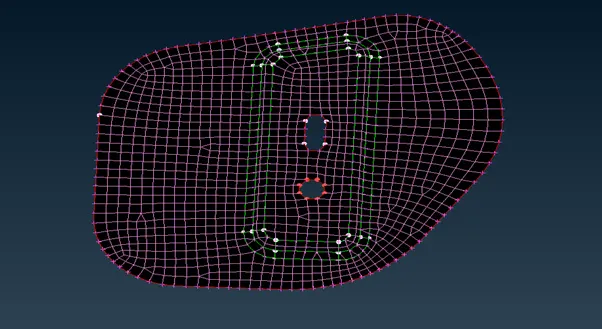
Fig - Mesh Generation of Latch 1
Similarly, all the steps are repeated for all the other components in the geometry and the desired mesh is obtained.
After obtaining the mesh for all the components we draw the shell as solid which can be seen in the below screenshots,
To draw the shells to solid under the presentation parameter in the quality criteria there is an option to make the shells as solid as shown,
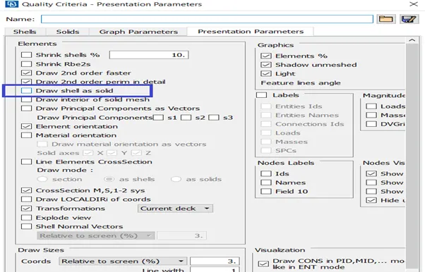
Fig - Activating shell to solid option
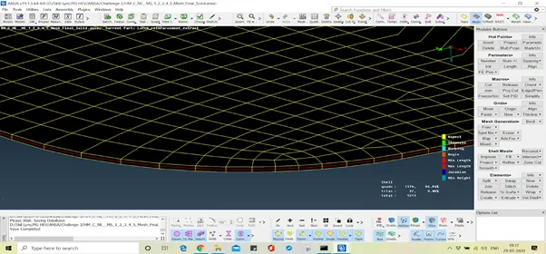
Fig - Solid Part Latch 1
Google Link for Model -
https://docs.google.com/document/d/175dAbig222caopgZgEVjH1zaC8jb7fpDEpLKjCHEwCs/edit?usp=sharing
Learning Outcome -
1] Move - This command can be used to move or slide the element freely in the coordinate system.
2] Origin - This command moves or adjust the element to their original position
3] Edge2Perimter - This command cut the macros along with the series of elements
Conclusion -
Here we can conclude that the hood model is successfully meshed after the geometry topo clean up with the help of the FEA tool ANSA. In the outer extract, some elements were unable to acquire according to the given quality criteria and failed to gain the feature due to minimum length which can be improved at the further stage before final analysis of the model.