Mesh the backdoor geometry of a car using the FEA tool HYPERMESH
Aim - To mesh the backdoor geometry of a car using the FEA tool HYPER-MESH
Objective - To perform the meshing on the given component to analyze the rear door failure in case of a rear crash test.
Procedure -
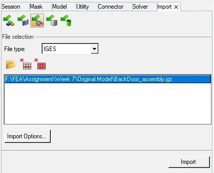
Step I - Import the geometry i.e, the .igs file (extension)using the file tab in the HYPER-MESH window.
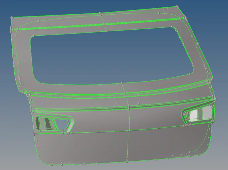
Step II - After importing the geometry, switching to the topo module. After this one by one, the component is identified as below
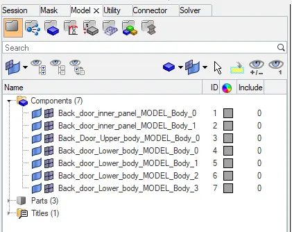
Step III - Select components one by one of the similar groups and check for the geometrical error and rectify them.
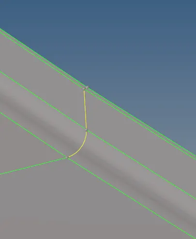
Error 1 - Two Surface joining together to form triple cons
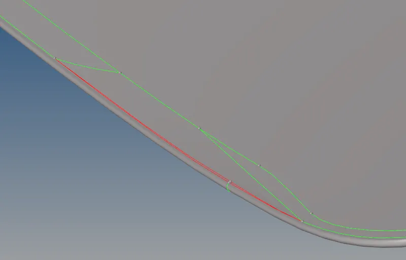
Error 2 - Gap between the surface
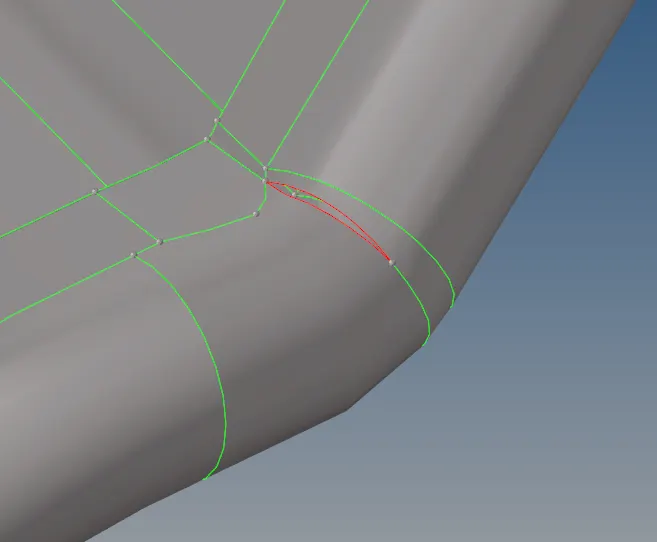
Error 3 - Gap between the surface
Step IV - Extracts mid surfaces of the components using the skin mid surface option.
Select any one original component let's say Back Door Inner with measuring the thickness of the component across various sections as 0.75 mm mid-surface is extracted using skin option of extraction.
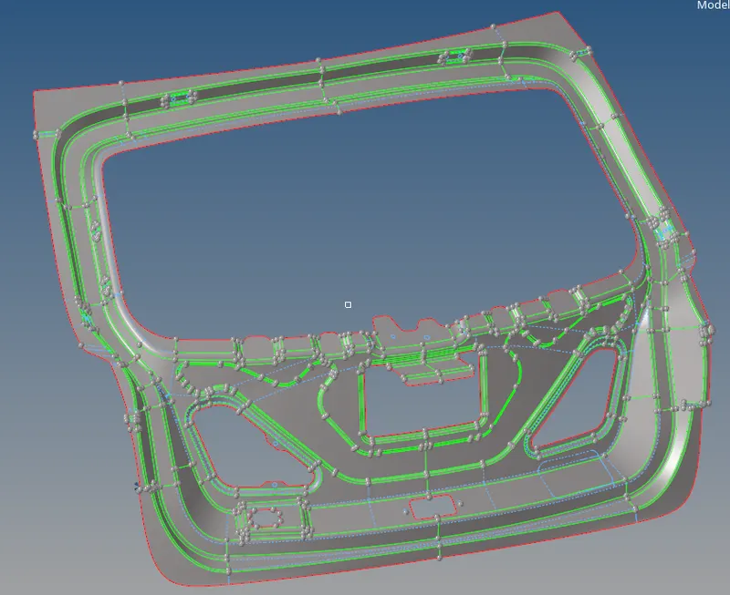
Fig - Mid Surface extraction of Back Door Inner
After Extracting the mid-surface of all the components each component mid-surface is saved as a new component to make it safe and confusions free from the parent geometry.
Step V - Deleting the half section of the mid surface to mesh.
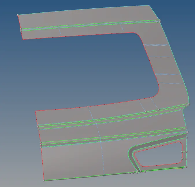
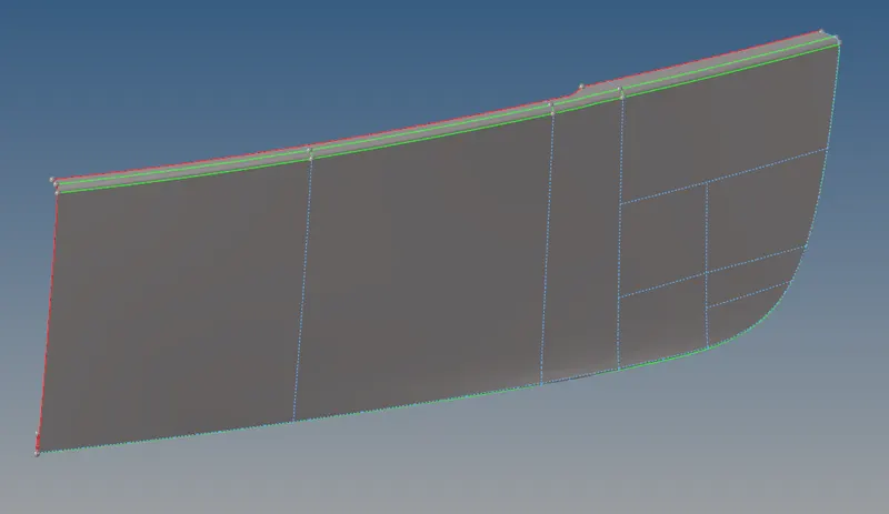
Back Door Upper Back Door Lower
Step VI - Meshing the geometry
Meshing is done using the automesh option with the target length of 5mm and quality criteria are set as below to make sure that there is no element failure at the end of meshing.

Fig - Mesh Parameters
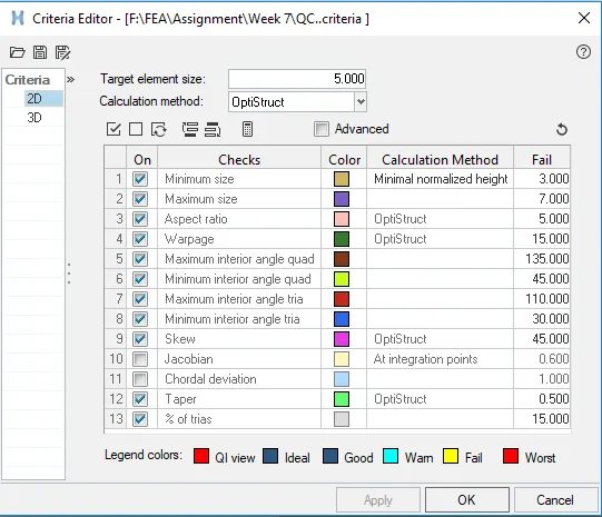
Fig - Quality Criteria
After assigning the quality criteria parameter user selects the back door lower component and makes the cuts and mesh the component as below to obtain a good mesh flow of the elements.
After making the cut geometry is mesh using automesh component in the 2D panel and with the help of various other commands like edit elements, rebuild, smooth, etc and mesh is obtained as shown below,
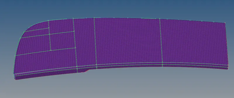
Fig - Mesh Generation of Back Door Lower
Step VII - Quality Check
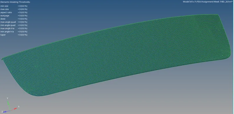
There is no element failing for the set quality criteria after cleaning up all the failed elements.
Step VIII - Reflecting the element to make the mirror of the given component
After creating the mesh the elements are reflected to get the exact mirror of the same component which would so the meshing time as well as the efforts of the user.
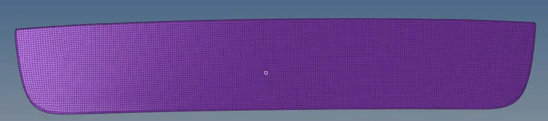
Step IX - Free Edge Check
After reflecting the element user check for the free edge and the equivalence of the element to ensure that that there is no gap present in the component the reflected element are equivalence using the equivalence option.
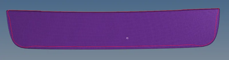
Similarly, all the steps are repeated for all the other components in the geometry and the desired mesh is obtained.
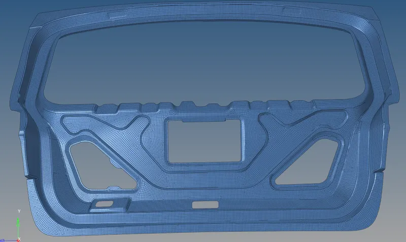
fig - Meshed Back Door Inner
 .
.
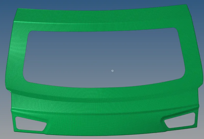
fig - Meshed Back Door Upper
Step X - Assign Property and Material Card to the components.
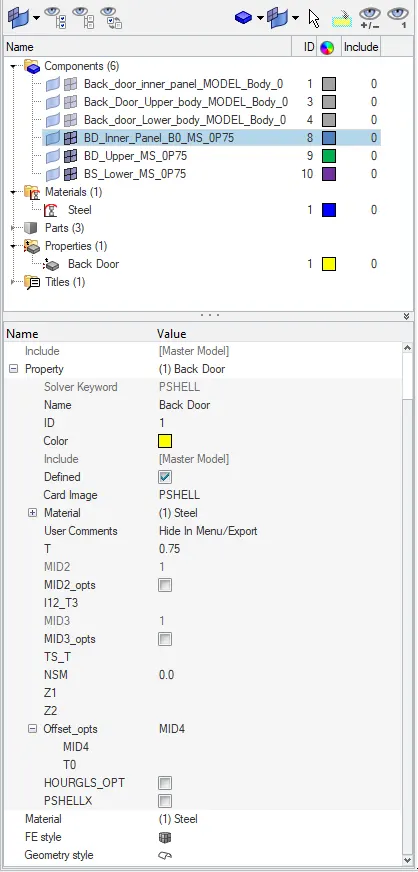
After obtaining the mesh for all the components we draw the shell as solid using the 2D element representation option which can be seen in the below screenshots,
To draw the shells to solid under the visualization panel there is an option 2D detailed element representation to make the shells as solid as shown,
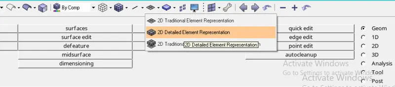
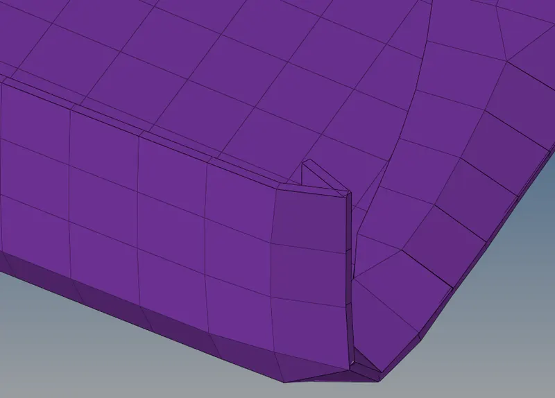
Fig - 2D Detailed Element Representation
Conclusion -
Here user can conclude that the Back Door model is successfully meshed after the geometry topo clean up and performing all the necessary steps with the provided quality criteria. Learning outcomes are tools used to perform meshing in HYPER-MESH.