MBD Simulation on IC Engine Valve Train
MBD Simulation on IC Engine Valve Train
1. AIM
To model & assemble IC Engine Valve Train and perform motion analysis of the assembly
2. OBJECTIVES
- Model the parts and assemble them in SolidWorks.
- Run the simulation using the below parameters
| Sl.No | CAM Lift (mm) | Speed (RPM) | Material |
| 1 | 3.5 | 1500 | Cast Carbon Steel |
| 2 | 6 | 1500 |
Cast Carbon Steel |
-
Obtain the Valve Lift.
-
Find the contact force between
- Cam and Push Rod
- Pushrod and Rocker Arm
- Rocker Arm and Valve
3. INTRODUCTION
The valve train refers to the assembly of components designed to open and close the intake and exhaust valves. The intake valves control the flow of air/fuel mixture (or air alone for direct-injected engines) into the combustion chamber, while the exhaust valves control the flow of spent exhaust gasses out of the combusion chamber once combustion is completed. The valvetrain consists of all the components responsible for transferring the rotational movement of the camshaft into the opening and closing of the intake and exhaust valves. Typical components are Camshaft, Pushrod , Rocker arm / bucket tappet , Valves, Spring, Valve mount.
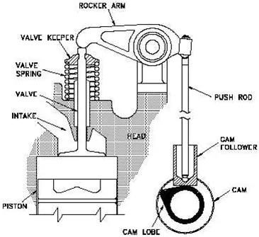
Credits: (1) http://commons.princeton.edu/63-tiger-cub/head/ (2) http://www.chevyasylum.com/85monte/rocker.html
A cam is a rotating or sliding piece in a mechanical linkage used especially in transforming rotary motion into linear motion. Cam takes the rotary motion of the engine and converts it into the reciprocating motion necessary to operate the intake and exhaust valves of the cylinders. Pushrod is a metal rod transmitting the reciprocating motion that operates the valves of an internal-combustion engine having the camshaft in the crankcase. Rocker arm is an oscillating lever that conveys radial movement from the cam lobe into linear movement at the poppet valve to open it. One end is raised and lowered by a rotating lobe of the camshaft while the other end acts on the valve. Valves are usually of the poppet type, although many others have been developed such as sleeve, slide, and rotary valves.
4.CAD GEOMETRY
4.1 Cam
Case 1: Cam lift of 3.5mm:
To calculate the distance between the two centres(L)
Given: R1 = 12.5; R2 = 5; Cam lift = 3.5mm
Cam lift = (L-R1)+R2
L = (12.5+3.5) - 5
L = 11mm
Case 2: Cam lift of 6mm:
To calculate the distance between the two centres(L)
Given: R1 = 12.5; R2 = 5; Cam lift = 6mm
Cam lift = (L-R1)+R2
L = (12.5+6) - 5
L = 13.5mm
4.2 Rocker arm
4.3 Pushrod
4.4 Valve mount
4.5 Valve
4.6 Assembly
5. MOTION STUDY SETUP
The motion features of the software can assist with a wide range of motion study depending on how complicated our requirements are, and they can be divided into three categories:
- Animation: If you simply wish to create some nice visuals for presentation or marketing without consideration of mass and gravity effects, then animation is for you.
- Basic Motion: For an extra layer of complexity that takes into consideration the effects of mass, springs, gravity and physical collision detection, then a Basic Motion study is more suited for your requirements.
- Motion Analysis: This is the top tier of motion study and takes into account a wider range of physical interactions such as impact effects, damping, force, momentum, etc.
5.1 Steps for motion analysis
- Activate the motiton analysis plugin of solidwokrs in add-ins tab.
- Select the motion analysis from the left drop down menu where there are other option including animation and basic motion. Animation will be selected as default so we need to select motiton analysis from the list.
- In all cases add the motor to the crank as input. The motor is set to 1500 RPM in all cases.
- As these different parts need to move relative to each other we need to give information to solidwworks that these are solid contact bodies. For this we use 'Contact' option from motion analysis options. Solid contact bodies to be set as given below in diagram.
- A spring is added between valve and the valve mount and the spring is pretensioned by giving extra lenght to the spring (extra 10mm lenght). Also the stiffness is increased to 10N/mm to make it more realisitic and effective.
- Select all the parts and change the material of the parts to Cast Carbon Steel.
- Motiton study properties can be selected to input necessary accuracy details and also to enable precision contact. As the motor is rotating in 1500rpm = 25 RPS. To get every degree change as a frame we need to set 25*360 = 9000 frames per second in the motion analysis settings. Also on the 'precision contact' setting to get good results.
- Add gravity in Y direction down using the gravity icon next to contact button.
- After including all settings to analyse the motion click the calculate button.
- Using 'Results and plots' option we can plot different graphs and get results.
Adding motor and spring settings
Contact settings
Material selection
Motion analysis properties
5.2 Animation
6. RESULTS, OBSERVATIONS AND CONCLUSIONS
The graphs obtained is a more precise since the frames per second(fps) used in motion analysis is high (9000) as well as we have used precision contact in motion analysis properties.
Case 1: Cam lift of 3.5mm:
- The linear displacement of the pushrod is 5mm.
- The linear displacement of the valve is 11mm.
- The maximum force between pushrod and cam is around 7990N.
- The maximum force between pushrod and rocker arm (magnitude) is around 8000N
- The force between rocker arm and valve (along x axis) is around 51N (friction)
- The maximum force between rocker arm and valve (magnitude) is around 1500N
- The contact force remain close to zero when cam is just rotatung in ideal state.
Case 2: Cam lift of 6mm:
- The linear displacement of the pushrod is 8mm.
- The linear displacement of the valve is 19mm.
- The maximum force between pushrod and cam is around 20000N.
- The maximum force between pushrod and rocker arm (magnitude) is around 18700N
- The force between rocker arm and valve (along x axis) is around 68N (friction)
- The maximum force between rocker arm and valve (magnitude) is around 3500N.
- The contact force remain close to zero when cam is just rotatung in ideal state.
Why the contact force between the Rocker arm and valve varies while measuring with respect to the X direction and measuring with respect to magnitude.
The magnitude of force represents net contact force between the parts. The contact force along the X direction is the frictional force between the bodies that arise due to the rocker arm sliding over the surface of the valve head. The magnitude of the contact force between the rocker arm and the valve pushes the valve downwards, but its X- component gives us only the friction force of the rocker arm sliding over the face of the valve head.
The change in direction of the force is because the rocker arm first slides towards origin giving a positive friction force (opposing the motion) and then slides away from the origin giving rise to friction in the negative x-direction. Therefore the plots are opposite to each other. The explanation is same for the cam lift of 6 mm, only it differs in magnitude of contact forces. The movement in this case is quite smoother compared to the cam lift of 3.5 mm as observed.
Conclusions
- The contact forces between components and linear displacement of the valve for the cam lift of 3.5mm is smaller than the cam lift of 6mm. This is basically due to the increase in lift which increases the net spring force developed in the system.
- The cam geometry affects the amount of opening of the valve through which the mixture enters the cylinder.
- The linear displacement of the valve is greater than the linear displacement produced by the cam along pushrod as the rockerarm length towards the valve is greater than that towards the pushrod, or we can say that the fixed point is closer to the pushrod.
- A minimum force is always present in the graphs due to the initial pretension state of the spring. This is seen in every contact force graph.
- The contact forces are at their peaks when the cam is at its topmost position.
- Vibrations can be observed during activation of valve due to friction and small jerking.
7. CAD FILE
The 3D model files : Link
https://drive.google.com/drive/folders/1YX1z7eS7FhiJ2ZnJDzE5PhXR_V4VTfaN?usp=sharing