MBD Simulation on a Piston Assembly
AIM:
To model and simulate the piston assembly using Solidworks.
OBJECTIVE:
1)To model and assemble all the parts.
2)To simulate it for a time period of 0-4 seconds.
3)To plot various graphs from it, compare and study from it.
THEORY:
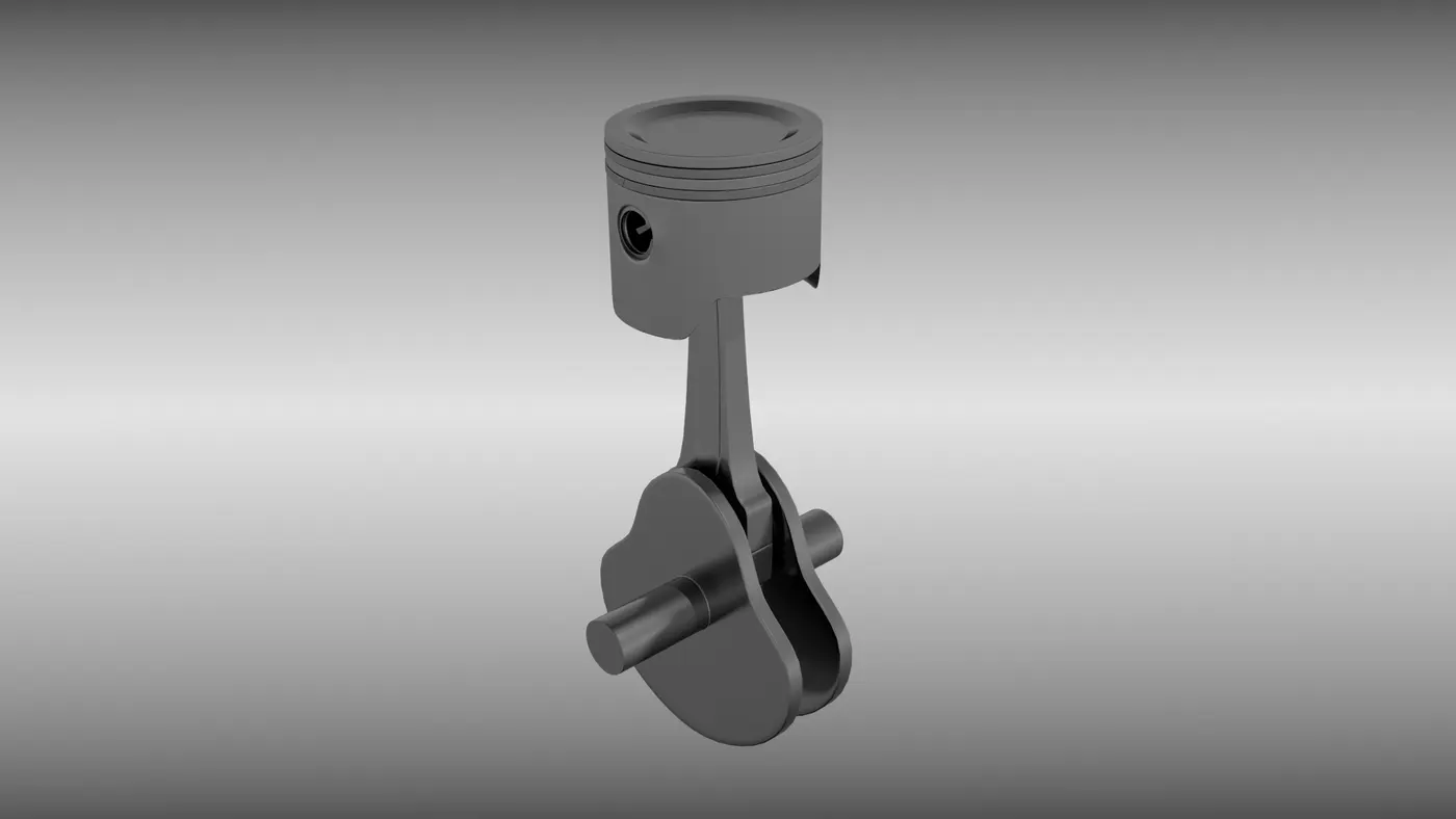
Piston assembly consists of a piston, piston rings, piston pin known as gudgeon pin,connecting rod and crankshaft. It is a type of slider crank mechanism which is used to convert linear motion into rotational motion and vice versa.
piston head is the top surface (closest to the cylinder head) of the piston which is subjected to tremendous forces and heat during normal engine operation. A piston pin bore is a through hole in the side of the piston perpendicular to piston travel that receives the piston pin.
Gudgeon pin is the main load carrying part in piston assembly. Small end of the connecting rod is connected to piston with the help of gudgeon pin.
The main function of a connecting rod is to form a link between a piston and crankshaft. A small end of the connecting rod is connected to the piston with gudgeon pin and big end is separated into two parts for ease of assembly with crankpin.
Crankshaft is the final link in the slider crank mechanism. The linear motion of a piston is converted into rotary motion of a crankshaft. The energy is generated into the combustion chamber by transforming the reciprocating motion of a piston into rotary motion of a crankshaft.
PROCEDURE:
1)Firstly, model all the parts of the piston assembly such as piston head, gudgeon pin, connectibg rod and crankshaft.
2)Then assemble all the parts and run motion analysis to the assembly for a period of 0-4 seconds.
3)Plot graphs for linear displacement of piston head for three cases
a)0mm offset
b)10mm positive offset
c)10mm negative offset
Compare all the three graphs and study from it.
MODELS:
1)PISTON HEAD
2)CONNECTING ROD:
3)END CAP:
4)GUDGEON PIN:
5)CRANK SHAFT:
ASSEMBLY:
GRAPHS FOR LINEAR DISPLACEMENT OF PISTON HEAD:
1)0mm offset:
2)10mm POSITIVE OFFSET:
3)10mm NEGATIVE OFFSET:
By Exporting all these 3 graphs to excel and superimposing them we get the following graph:
SIMULATION:
I have attached the link below:
https://www.youtube.com/watch?v=YRhGjFe9R6g&feature=youtu.be
RESULT:
Thus all the parts are modelled, assembled and simulated. Various graphs are plotted for different cases in piston assembly, compared and studied.