MBD Simulation on a Piston Assembly
MBD Simulation on a piston assembly
1. Aim
Model all the parts and then assemble them in SolidWorks. The motion analysis is going to be carried out in three different conditions
2. Objective
- To find motion study on the piston assembly based on the three different conditions of the wrist-pin
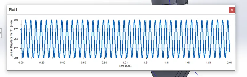
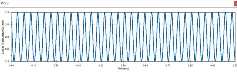
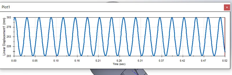
- Obtain the Linear displacement of the Piston Head in all the three cases. Then export the graphs into Excel.
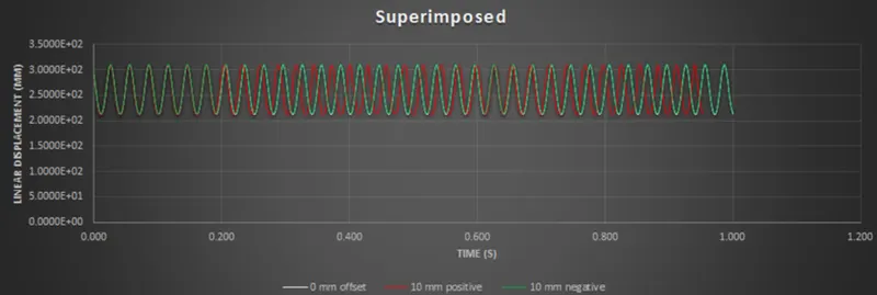
- Then Superimpose all the three graphs into a single graph.
| Sl.No |
Wrist Pin Offset ` |
Crank Speed (Rpm) |
| 1 | "0" mm | 2000 |
| 2 | 10 mm Positive | 2000 |
| 3 | 10 mm Negative | 2000 |
3. Theory
An internal combustion engine is acted upon by the pressure of the expanding combustion gases in the combustion engine space at the top of the cylinder. This force then acts downwards through the connecting rod and onto the crankshaft. The connecting rod is attached to the piston by a swivelling gudgeon pin (wrist pin). This pin is mounted within the piston
A piston must follow a cyclical process in order for it to continuously convert heat energy to work, and there are many ways to complete this cycle. For example:
- By inputting heat to the gas inside the cylinder, the gas will expand increasing the volume in the cylinder and provide useful work.
- By removing heat from the cylinder, the gas's pressure will decrease, allowing it to be compressed more easily.
- By inputting work to the piston, the piston will compress back to its initial state, ready to perform the cycle once again.
4. Procedure
- First step is 3D modeling of the required parts like Piston, connecting rod, gudgeon pin, crank
- Then assembly of all the parts should be done
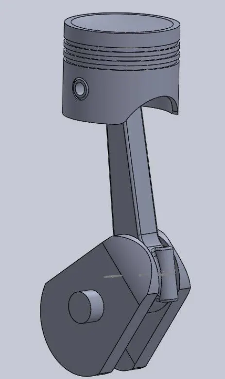
Assembeled drawing
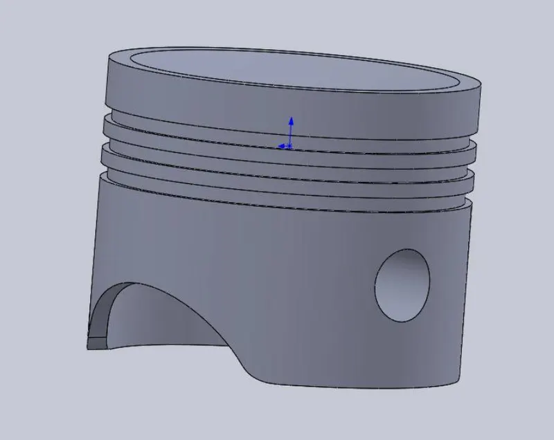
Indivisual parts
- Piston
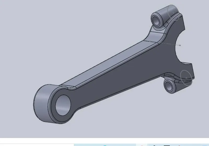
- Connecting rod
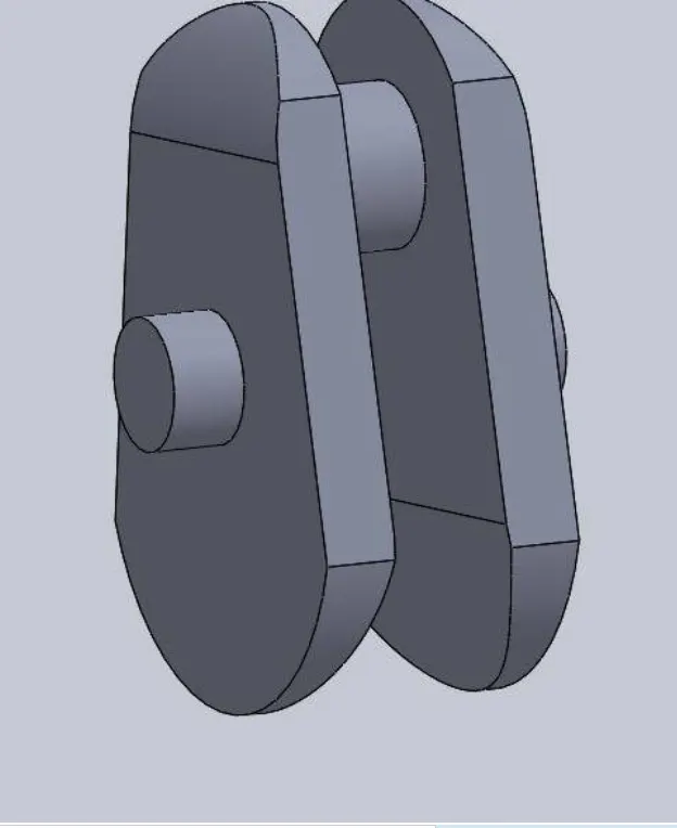
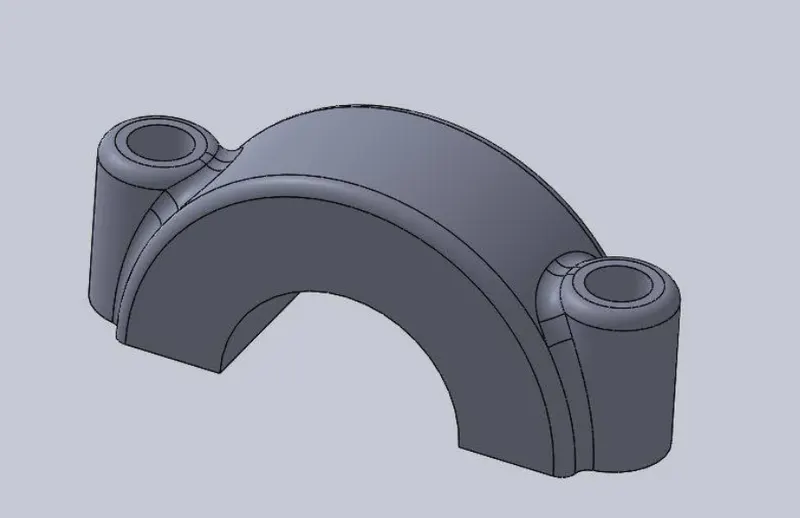
- Crank
- Gudgeon pin
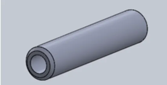
- End cap
Assembly
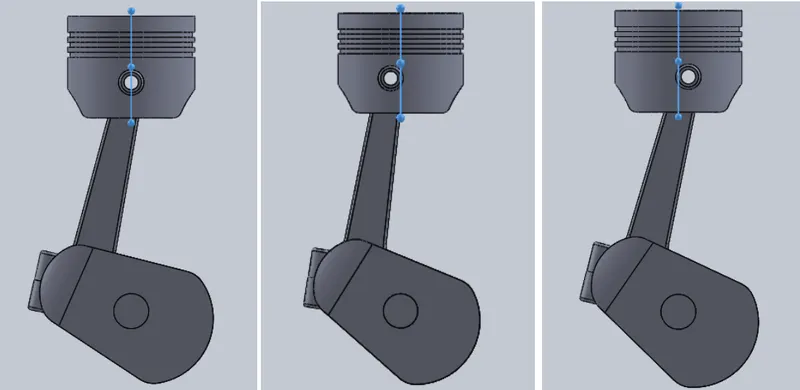
0mm offset 10mm positive offset 10mm negetive offset
Case 1
The wrist pin offset is 0
- Provide an RPM of 2000 to the crank
- Change the fps to 7200 with the presice contact and apply gravity on y axis
- Run the simulation
- Then calculate the linear velocity of the piston by giving necessary inputs
- Extract the requried graph
Link for animated video
https://drive.google.com/file/d/1GTcZmEJOcDHZK5CBJ2GITi57s_qkkR_b/view?usp=sharing
Case 2
The wrist pin is 10mm possitive offset
- Provide an RPM of 2000 to the crank
- Change the fps to 7200 with the presice contact and apply gravity on y axis
- Run the simulation
- Then calculate the linear velocity of the piston by giving necessary inputs
- Extract the requried graph
Link for animated video
https://drive.google.com/file/d/1IDqtC7QKXCwCs0LsRcTNeUARbpZgsoWM/view?usp=sharing
Case 3
The wrist pin is 10mm negative offset
- Provide an RPM of 2000 to the crank
- Change the fps to 7200 with the presice contact and apply gravity on y axis
- Run the simulation
- Then calculate the linear velocity of the piston by giving necessary inputs
- Extract the requried graph
Link for animated video
https://drive.google.com/file/d/1IDqtC7QKXCwCs0LsRcTNeUARbpZgsoWM/view?usp=sharing
Combined result
Result and conclusion
- From the graph it shows that there is slight differences in linear velocities in all 3 cases
- From the superimposed graph shows that frequency of the dispalacement of the piston is increses from negative to positive offset
- The maximum and minimum values of all the graph is almost same