MBD Simulation on a Piston Assembly
MBD Simulation on Piston Assembly:
Aim: To conduct a motion study on the piston assembly and plot the results for linear displacement of the piston at the given three conditions.
Theory: The piston assembly is one of the most important parts of an IC engine and the main purpose of the piston assembly is to transform the linear motion created due to the combustion in the cylinder into rotary motion. The piston along with the gudgeon pin, connecting rod and the crank make this transformation of linear motion to rotary motion happen smoothly.
This assembly consists of a piston, a gudgeon pin that joins the piston and the connecting rod, a connecting with an end cap that connects the crank to this mechanism. The connecting rod has a smaller end and a bigger end bearing. The gudgeon pin connects the smaller end of the connecting rod with the piston. The piston rings help in restricting the flow of hot gases into the crankcase and an oil rings helps in lubrication of the piston. They also help in transmitting the heat generated to the walls of the cylinder. They also restrict the flow of oil from the crankcase to the cylinder head. Piston mainly transfers the force generated during combustion to the connecting rod and the crank. The connecting rod has the main function of joining the crank and the piston with the help of a gudgeon pin.
Pistons are usually made of low carbon steel or aluminium alloy. Connecting rods are usually made of steel, aluminium or sometimes with titanium. The gudgeon pin is made of steel alloy. The cranks are usually made of forged steel or cast iron.
Introduction: The following data has been given to perform a motion study on the piston assembly and to obtain the plots for linear displacement to see the difference in various conditions provided.
To model all the parts and then assemble them in SolidWorks. The motion analysis is going to be carried out in three different conditions,
|
Sl.No |
Wrist Pin Offset ` |
Crank Speed (Rpm) |
|
1 |
"0" mm |
2000 |
|
2 |
10 mm Positive |
2000 |
|
3 |
10 mm Negative |
2000 |
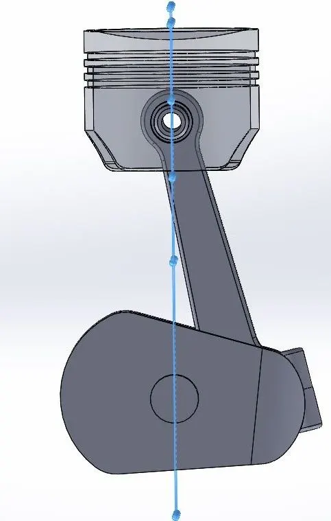
Wrist Pin Offset - The position of the wrist pin is going to be varied as followed. But the centre of the axis of the piston head and the crank are coincident to each other (i.e) They will be on the same plane in all the three cases.
"0" mm Offset
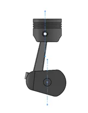
10 mm Positive Offset - If the crank rotation is in the clockwise direction.
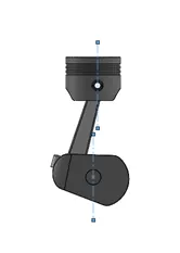
10 mm Negative Offset - If the crank rotation is in the clockwise direction.
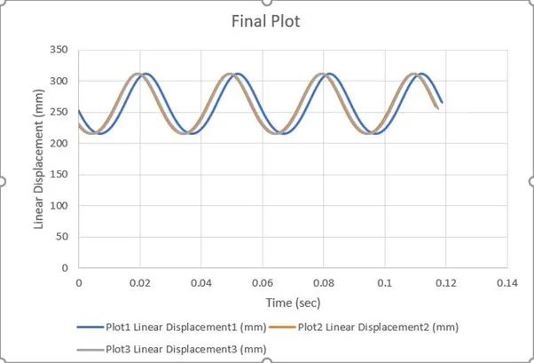
To obtain the Linear displacement of the Piston Head in all the three cases. Then export the graphs into Excel. Then Superimpose all the three graphs into a single graph.
Motion Study Setup:
The motion study of the piston assembly is done by first creating the individual parts in SolidWorks and then assembling them later as follows:
Piston:
First, we create the piston using the following sketch and then use the revolved cut option. Then we create a couple of extruded cuts in the piston and also use the extruded boss base option to form the sleeves for gudgeon pin. We also use revolve cut option to create slots for the piston rings.
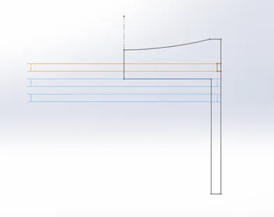
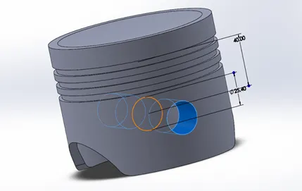
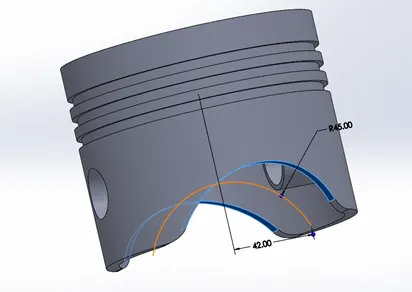
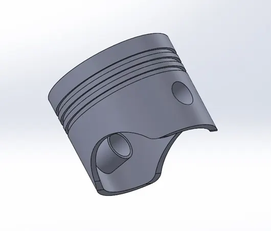
The final piston structure looks the picture below.
Gudgeon pin:
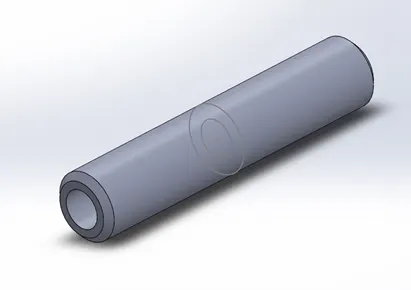
By drawing a couple of circles and by using the extruded boss base option and using the fillet tool will create the gudgeon pin.
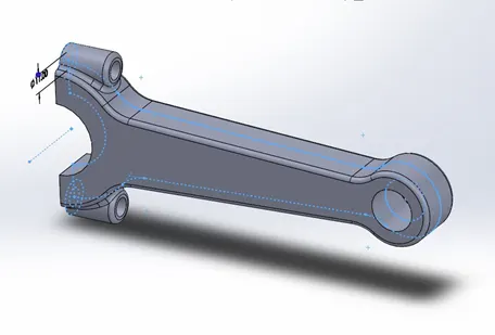
Connecting Rod:
By Using Extruded boss base and extruded cut options for holes to join with end cap and also fillet tool will help in creating the connecting rod as shown below.
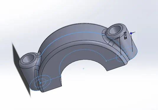
Endcap:
The endcap is also created using the extruded boss base and extruded cut for bolt holes and fillet tool to give smooth curvy edges.
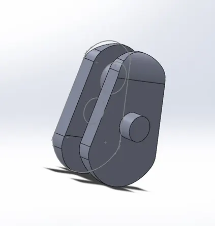
Crank:
This is created using a sketch of a trapezium kind of shape and using extruded boss base as well as the extruded cut for the bolt holes. Also the fillet tool has been used to smoothen the edges.
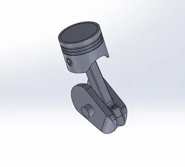
Assembly: All parts are assembled and the piston assembly is created by making the planes of the parts coincident.
Motion Study and Plots:
Case-1:
|
Sl.No |
Wrist Pin Offset ` |
Crank Speed (Rpm) |
|
1 |
"0" mm |
2000 |
In this case, the right plane of the piston and the assembly are made coincident.
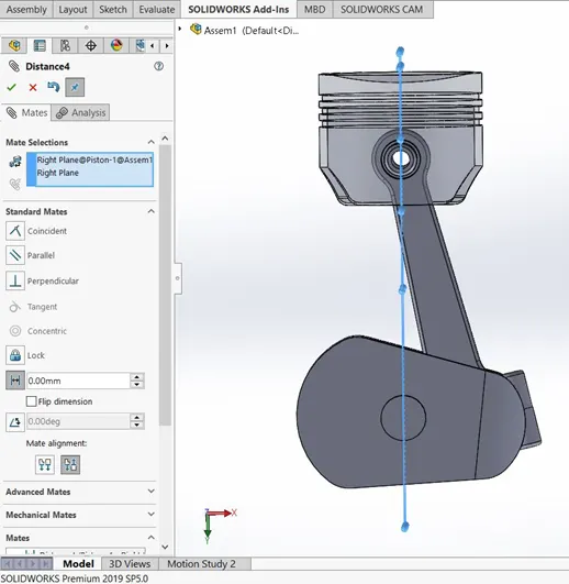
the animation is as follows:
The plot for linear displacement is as follows:
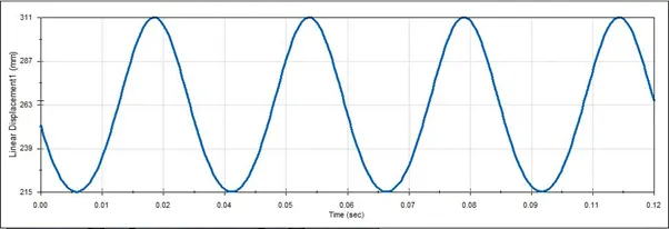
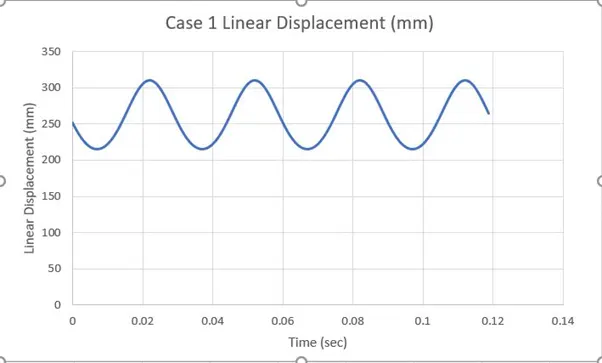
The plot shows the steady motion of the piston as a function of time and the linear displacement beginning at around 255mm.
Case-2:
|
Sl.No |
Wrist Pin Offset ` |
Crank Speed (Rpm) |
|
2 |
10 mm Positive |
2000 |
In this case, the right plane of the piston and right plane of the assembly are given a distance mate of 10mm in positive direction.
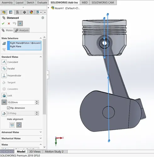
The animation is as follows:
The plot for linear displacement is as follows:
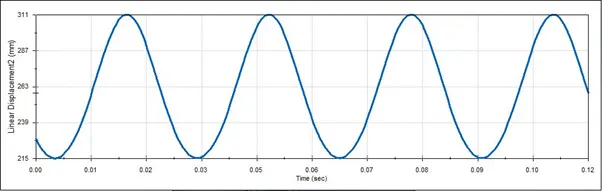
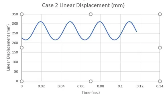
The plot shows the steady motion of the piston as a function of time and the linear displacement beginning at around 225mm.
Case-3:
|
Sl.No |
Wrist Pin Offset ` |
Crank Speed (Rpm) |
|
3 |
10 mm Negative |
2000 |
In this case, the right plane of the piston and right plane of the assembly are given a distance mate of 10mm in a negative direction.
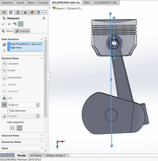
The animation is as follow:
The plot for linear displacement is as follows:
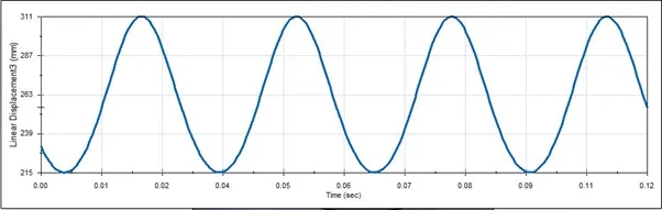
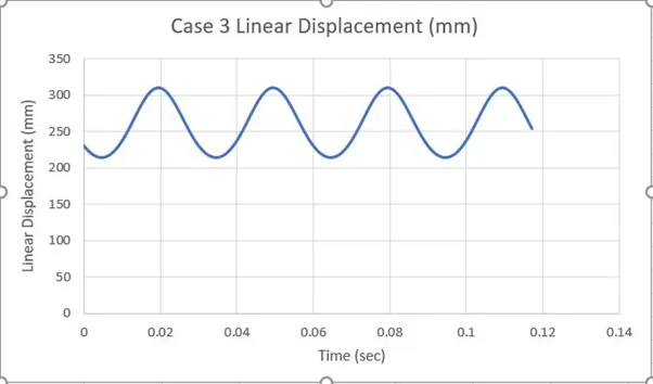
The plot shows the steady motion of the piston as a function of time and the linear displacement beginning at around 230mm.
Now all three cases are superimposed for comparison analysis.
Conclusion:
The plot shows the comparison between all the three cases and we can see that at most parts the variation of linear displacement in all the three cases are same and there are no distinct shapes in the curve. The only differences are the initial linear displacement which seemed to be almost the same for both the positive and negative offset cases but had a difference when there is no offset between the wrist pin and the crank.
From the results, we can say that basically the wrist pin offset gives a couple of major advantages for the functioning of the IC engine. The first one being, the improvement in the noise characteristics of the engine due to the piston slap to the top dead centre. The second one being, to improve engine output by reducing internal friction.
So, the Offset of the piston is an idea that helps the engine in many ways by reducing the noise characteristics as well as the friction characteristics to improve the efficiency.