Internal Geneva Mechanism
Motion Study of Internal Geneva Mechanism:
Aim: Creating a 3d model of the internal Geneva mechanism and its components and by assembling them to create a motion study and by comparing various results.
Theory:
The Geneva Mechanism is a gear mechanism that changes a continuous rotation movement into intermittent rotary motion.
The rotating drive wheel is having a pin that reaches into a slot located in the driven wheel that moves it one step at a time. The driver wheel also has an extruded circular blocking disc that "locks" the rotating driven wheel in position between steps. These are usually seen in mechanical watches and movie projectors.
Types
- External Geneva Mechanism
- Spherical Geneva Mechanism
- Internal Geneva Mechanism
External Geneva Mechanism:
Here the driven wheel is connected to the driver component externally. As you can see below
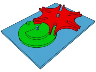
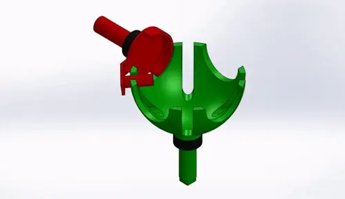
Spherical Geneva Mechanism:
Here the driven and driver components are spherical and are mostly designed in a way where the axes of the two components are perpendicular to each other. As you can see below
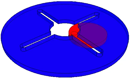
Internal Geneva Mechanism:
Here the driven wheel is connected to the driver component internally. As you can see below.
Procedure:
- Creating driver & driven components of the internal Geneva mechanism
- Assembling driver & driven components to form as a Geneva mechanism
- Creating a motion study at 10RPM at 60 frames per second.
- Creating a motion study at 20RPM at 120 frames per second.
- Creating plots for contact forces, Angular displacement, and angular velocity.
- Comparing all the results with and without precision contact.
Motion Study Setup:
Given Data:
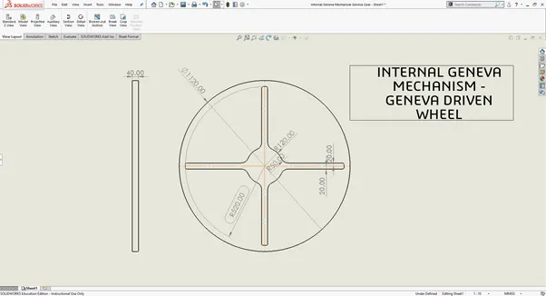
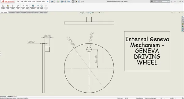
First we create the Driver wheel according to the given dimensions as shown below
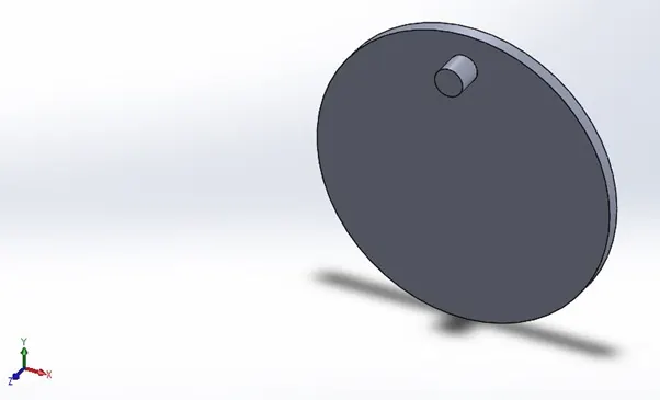
Next we create the driven wheel as per the dimensions given:
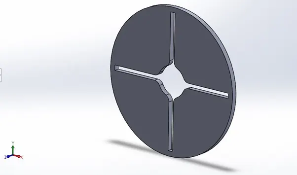
Next we find out the distance between central axis of driver and driven wheels by drawing a tangent circle to the slots with a dimension of 320mm from the given information. The distance between the centres is found out to be
Now we have to measure the distance between the centres of the driver and driven wheels to find the distance between the axis of both the wheels. This value is found out to be 222.71mm.
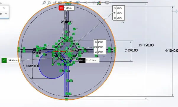
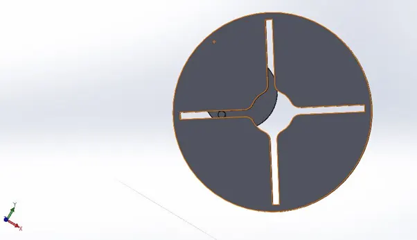
Now we have assembled driver and driven components by selecting the assemble option. Here the components are constrained by mating them with the planes of the assembly and fixing the distance between the central axes of the two components. Once all this is done, the final assembly looks something like the picture below.
Condition 1 (10RPM 60FPS):
Now we have to do a motion study and in the motion analysis, we have given the following conditions at 10RPM at 60FPS with precision and without precision contact and also have selected the material as steel (dry). Also, we have fixed a time period of this study as 10sec. These are shown in the below pictures.
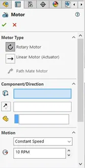
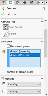
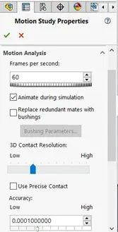
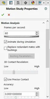
After applying all these conditions, we click on calculate the motion study button and then plot the graphs for contact force between driver and driven wheels as a function of time with and without precision contact, Angular displacement of the driven wheel and angular velocity of the driver component. The results obtained are showcased below.
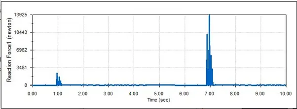
contact force vs time without precision contact.
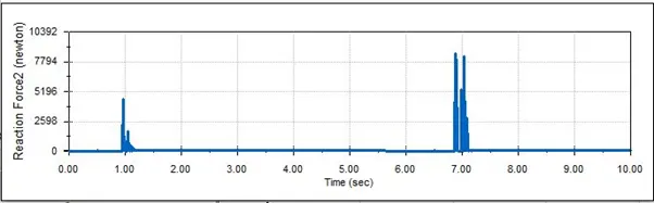
Contact force vs time with precision contact.
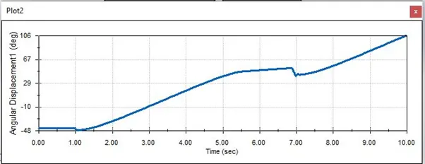
Angular displacement vs time of the driven wheel. Without precise
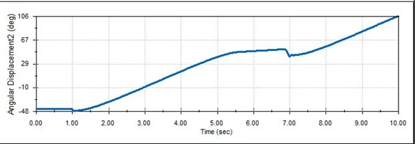
Angular Displacement vs time for the driver wheel with precise.
Condition 1
Up on Observing the plots of the contact force vs time with and without precision contact, we can say that having the precision contact turned on helps us in giving more accurate results as the force components are distinct and variation of contact force while the components touch each other to create the movement is observed clearly at various points of time.
The angular displacement of the driven wheel is observed to be at its peak when the driver's pin is at the deepest point of the slot that it can reach and slowly keeps decreasing as the pin comes out of the slot. This variation can be clearly seen in the plot.
So these are some of the observations that we can make by looking at the plots of contact forces, angular displacement, of the components.
Condition 2 (20RPM 120FPS):
Now we create another motion study and in the motion analysis, we give the following conditions of 20RPM at 120FPS with and without precision contact and also choose the material as steel (dry). Also, we fix a time period of this study as 8sec. These are shown in the below pictures.
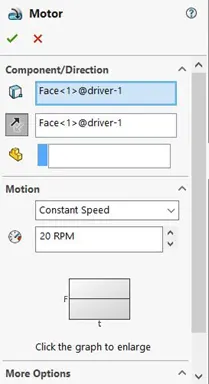
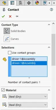
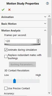
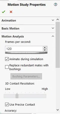
By applying all these conditions we have calculated the motion study button and then plot the graphs for contact force between driver and driven wheels as a function of time with and without precision contact, Angular displacement of the driven wheel and angular velocity of the driver component. The results obtained are showcased below.
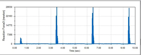
contact force vs time without precision contact.
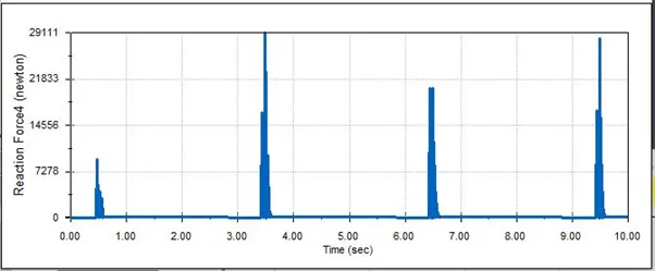
contact force vs time with precision contact.
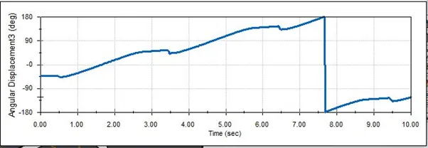
Angular displacement vs time of the driven wheel without precision.
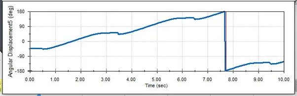
Angular displacement vs time of the driver wheel with precise.
Condition 2
As discussed in the previous analysis from the first condition, the plot of the contact force with precision is more helpful in giving us a clear idea of how the force varies with time as the driven comes in contact with the driver. The highest force here is seen during the first contact of the driver wheel's pin with the slot of the driven wheel and it decreases as it goes deep into the slot and comes out of it.
The precision of the calculation of the distance between the axis of the driver and driven help in decreasing the impact of contact force while entering the slot and cause the movement.
When the RPM of the motor is increased in this condition, we are able to get more cycles of movement in the same time period and it helps us analyse the motion over greater displacement compared to the first condition.
Conclusion:
- Forces are seen at 10rpm analysis are lesser than the forces seen in the 20rpm condition.
- 20rpm gives more cycles of movement compared to 10rpm in a given time period. So analysing both the conditions helps in getting to know the variation of forces with increase in the speed of driver.
- Turning on the precision contact option helps in getting to know the forces during the contact more precisely and increase the efficiency of the mechanism.
The Internal Geneva Mechanism is created and plots are made and the analysis is done.