MBD Simulation on a Piston Assembly
AIM:- MBD Simulation on a Piston Assembly
OBJECTIVE:-
Model all the parts and then assemble them in SolidWorks. The motion analysis is going to be carried out in three different conditions,
| Sl.No |
Wrist Pin Offset ` |
Crank Speed (Rpm) |
| 1 | "0" mm | 2000 |
| 2 | 10 mm Positive | 2000 |
| 3 | 10 mm Negative | 2000 |
Wrist Pin Offset - The position of the wrist pin is going to be varied as followed. But the center of the axis of the piston head and the crank are coincident to each other (i.e) They are on the same plane in all the three cases.
"0" mm Offset - Run a simulation as seen in the video.
10 mm Positive Offset - If the crank rotation is in the Clockwise direction
Obtain the Linear displacement of the Piston Head in all the three cases.
Then export the graphs into Excel.
Then Superimpose all the three graphs into a single graph.
MULTIBODY SIMULATION:-
The movements of a physical body can be measured by using the study of kinematics and dynamics where it can use all the relative terms of acceleration and motion.
Connections between the bodies can be modeled with kinematics constraints (such as joints) or force elements (such as spring dampers).
Unilateral constraints and coulomb friction can also be used to model frictional contacts between bodies.
Multibody simulation is a useful tool for conducting motion analysis.
It is often used during product development to evaluate characteristics of comfort, safety, and performance.
Types of components that can be studied through multibody simulation range from electronic control system to noise, vibration and harshness.
Following rules and experiences, the 3D model in MBS format, multiple boundaries, kinematics, forces, moments or degrees of freedom are used as input to generate the MBS model.
Modeling of all parts:-
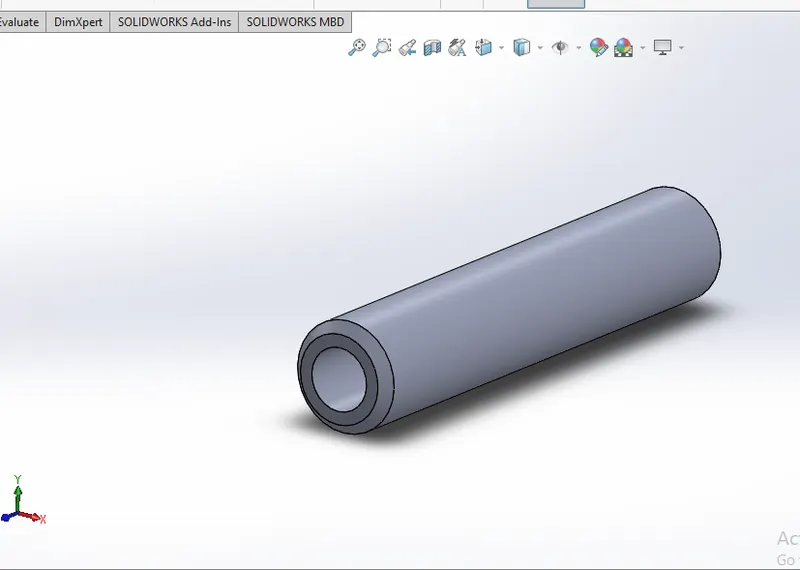
pinston pin:-
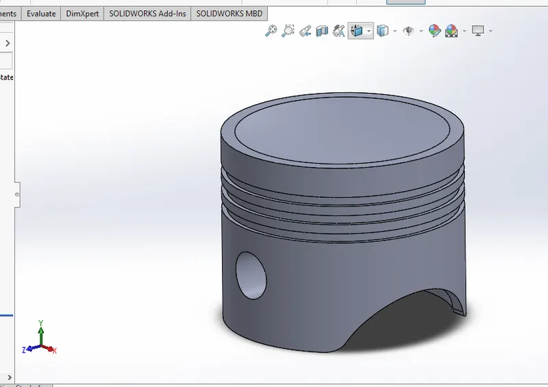
PISTON:-
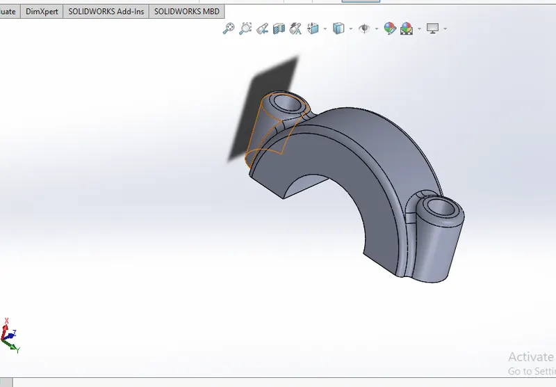
Connecting rod End cap:-
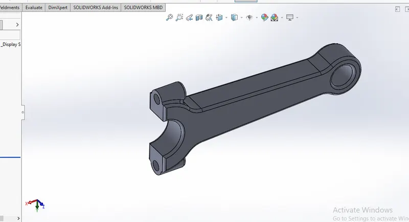
CONNECTING ROD:-
Piston Assembly:-
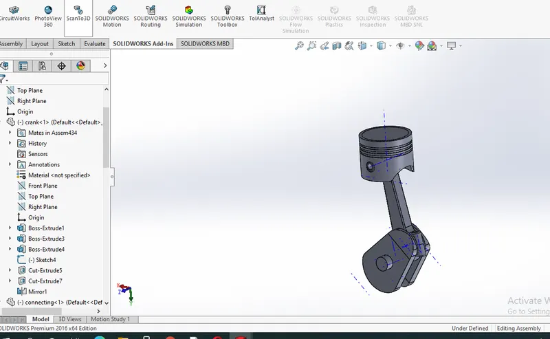
OBJECTIVE:-
Model all the parts and then assemble them in SolidWorks. The motion analysis is going to be carried out in three different conditions,
| Sl.No |
Wrist Pin Offset ` |
Crank Speed (Rpm) |
| 1 | "0" mm | 2000 |
| 2 | 10 mm Positive | 2000 |
| 3 | 10 mm Negative | 2000 |
Wrist Pin Offset - The position of the wrist pin is going to be varied as followed. But the center of the axis of the piston head and the crank are coincident to each other (i.e) They are on the same plane in all the three cases.
"0" mm Offset - Run a simulation as seen in the video.
10 mm Positive Offset - If the crank rotation is in the Clockwise direction
Obtain the Linear displacement of the Piston Head in all the three cases.
Then export the graphs into Excel.
Then Superimpose all the three graphs into a single graph.
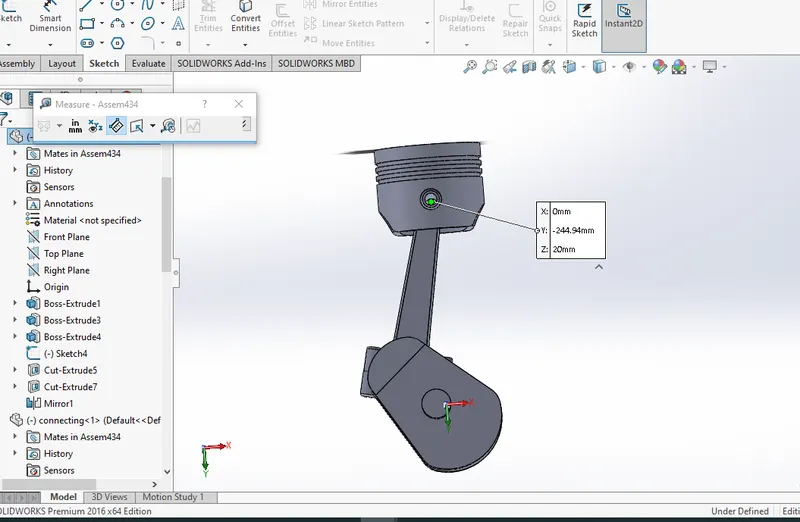
Obtained the Linear displacement of the Piston Head
10 mm Positive Offset - If the crank rotation is in the Clockwise direction.
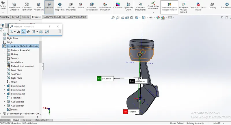
Obtained the Linear displacement of the Piston Head
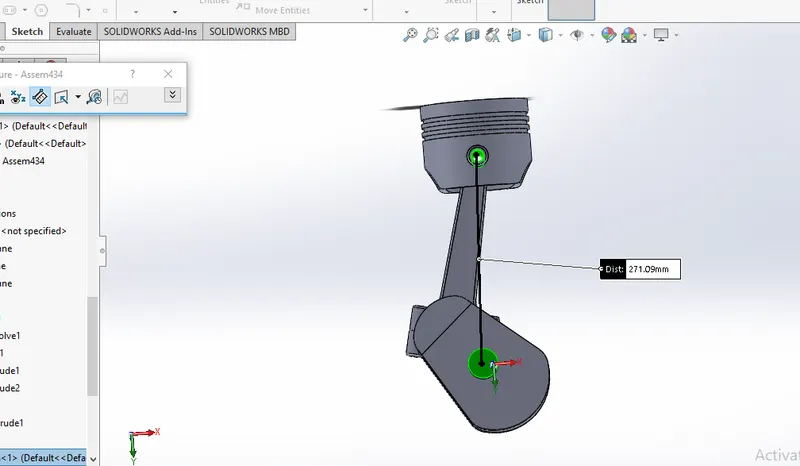
Obtained the Linear displacement of the Piston Head
Observation:
The amplitude varies for different cases.
Offsetting 10mm negative will make the crankshaft to put extra force to pull the piston from TDC to BDC.
The point in making offset is to increase the maximum displacement and angular velocity to be high in all cases.
Stresses will be developed in wrist pin by offsetting