Introduction to REVIT concepts
Introduction:
Revit is a Building Information Modelling software for architects, landscape architects, structural engineeers, mechanical,electrical and plummbing(MEP) engineers, designers and contractors. Its powerful tools lets us to use the intelligent model-based process to plan, design, construct and manage buildings and infrastructure.
- Charles River Software originally developed the software in 1997, renamed Revit Technology Corporation in 2000, and acquired by Autodesk in 2002.
- Autodesk Revit is BIM software for Architects, Interior Designer, Landscape Architects, Structural Engineers, MEP Engineers, Contractors, and more.
- Revit can be used as a very powerful collaboration tool among different disciplines in the Architecture, Engineering, and Construction (AEC) industry.
- Revit has a huge library for modeling in the software itself and supports plug-ins, advanced data management systems, and energy modeling analysis.
- Revit modeling process is complicated and not easy for a first-time user.
- Software required better hardware, 40% more expensive than Autodesk CAD but higher productivity.
- For architects and interior designers, the software is being used to create construction documents.
- Most of the commercial interior design/architectural design firms use Revit.
- Not much of renderings features, but support Virtual Reality plugins.
- Collaborate with CAD drawing users.
1.
Aim: To create new project and name the project appropriately.
Procedure:
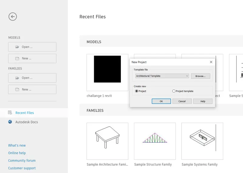
1. Initially open the revit software.
2. Then go to new option in the model.Choose architecture template, then click on project and then OK. Now, the Revit software opens.
3. Then, click on the save icon
4. Now, type the desired file name and save it in the desired location.
RESULT :
2.
Aim:To save a project file. Then, close and open the file using icon from file toolbar.
Procedure:
1. Open the revit software and click on new.Then choose architectural template, create new project and then OK.
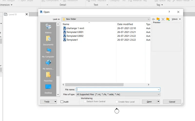
2. The revit file opens click on the save icon . Then a window opens.
3. Type the desired file name and save it in the desired location.
4. Hence,the file name is saved.
5. Now, we have to close and open the file using icons from file toolbar.
6. Again open the revit software.
RESULT :
3.
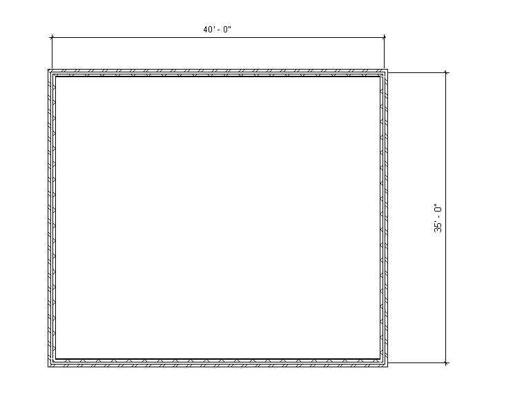
Aim: To familiarise with the options to draw a wall from architectural or structural toolbar, then to create a rectangular layout of a walls of about 40'x35'.
Procedure:
1. Initially open the Revit file.
2. Then choose the imperial template.
3. Then go to the Architecture panel where you have variety of options to develop a structure.
4. Choose the wall option in the Architecture panel.
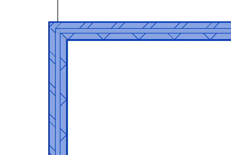
5. Create a rectangular wall of 40'x35'
RESULT :
4.
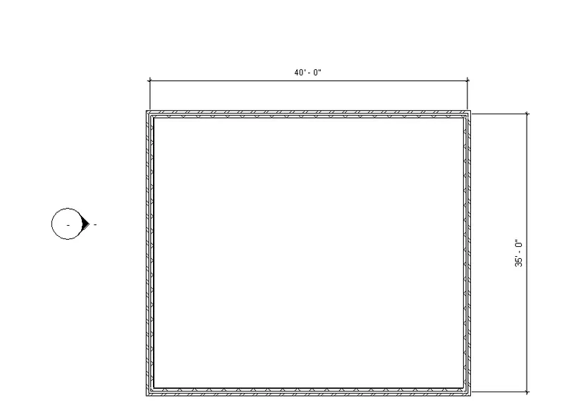
Aim: To dimension the wall layout by using the aligned option in annotate toolbar.
Procedure:
1. Initially open the Revit software.
2. Create a wall in the imperial template as given below.
3. Now, go to annotate tab, choose aligned dimension.
4. Then, provide the dimension to the wall thus created.
RESULT :
5.
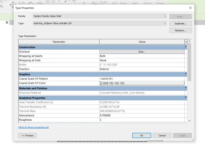
Aim:To use the properties browser to switch between different types of wall.
Procedure:
1. Initially open the Revit software.
2. Create a wall in the imperial template as given below.
3. Now, select the wall createdand then go to properties panel in the eft side of your drawing area.
4. In that, go to edit type option where you can change the wall types.
5. Similarly different wall types can be chosen.
RESULT :
6.
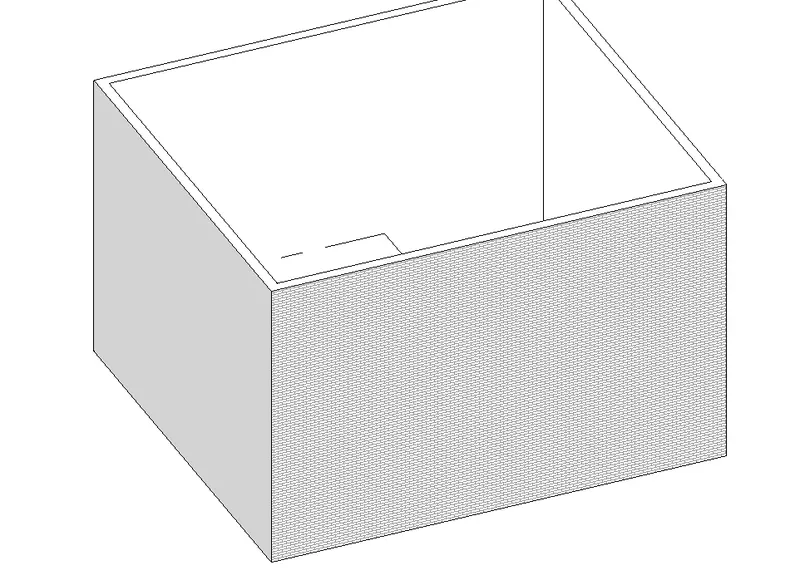
Aim: To create the 3D view from the view toolbar and then save the view with appropriate name.
Procedure:
1. Initially open the Revit software.
2. Create a wall in the imperial template as given below.
3. Now we have to create the 3D view of this wall.
4. For this go to view tab and choose 3D view option.
5. Hence, the 3D view is developed as given below:Now, we have to save the view, for this click the full navigation wheelon the navigation bar.
6. Then, right click the steering wheel and click save view.
7. Now, enter a name for the new 3D view and then click ok.Hence, the view is saved.
RESULT :
7.
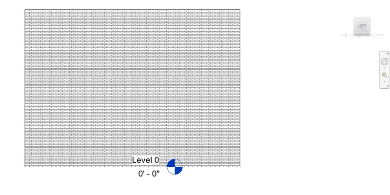
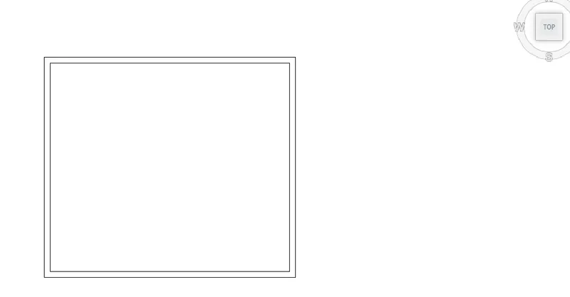
Aim:To navigate through the 3D model using the view cube. Orbit/pan through the model layout created.
Procedure:
1. To orbit/ pan we have to click on the view cube and then change the orientations to view different views.Similarly different views can be obtained by simply orbiting through the view cube.
RESULT :
8.
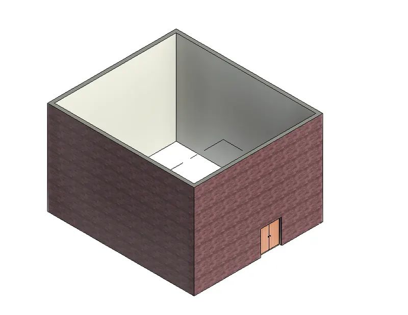
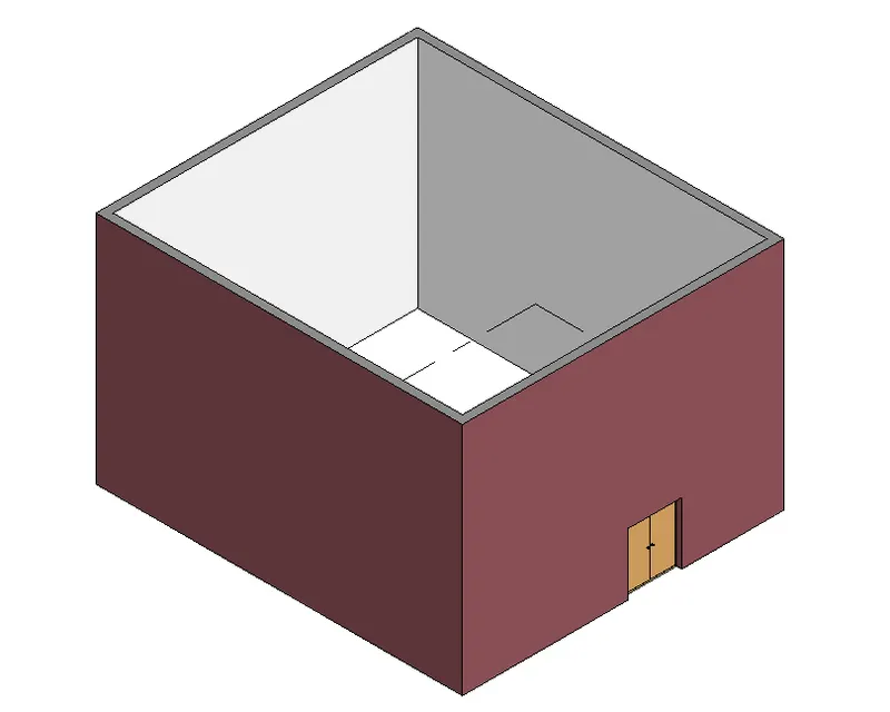
Aim:To switch model to shaded, realistic, hidden lines options by using the visibility settings options.
Procedure:
1. Take the 3D view of the wall.
2. Now, go to visibility section which can be accessed from the below panel (2nd from left).
3. Presently the visibility is hidden, now we can change visibility to shaded.Again change the visibility to realistic.
RESULT :
9.
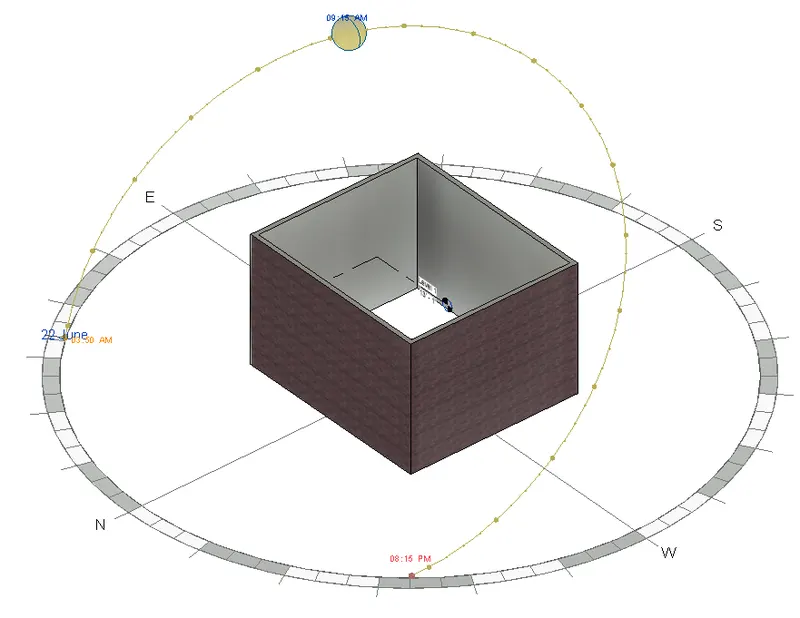
Aim: To turn the sunpath on and off to view the shadings in the layout created.
Procedure:
1. Create the relaistic view of the 3D wall.
2. Now, make the sun on and off to view the shadings.
3. Sun path off view:Sun path ON view:
RESULT :
10.
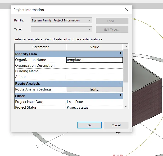
Aim:To use the manage toolbar to enter project settings, project name and project issue date.
Procedure:
1. Go to manage toolbar.
2. In this choose project information .Now, fill in the necessary data.
3. Now, click ok. Hence completed.
RESULT :
11.
Aim: To Analyze toolbar in Revit and its benefits.
PROCEDURE:
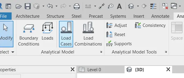
1. Analyze toolbar in Rivet helps in evaluating the building performance - analyzing the model by boundary conditions, loads etc.,
2. It evaluates the sustainability of the model.
3. Boundary condition: We can give the line and area boundary conditions to the model.
4. Loads : We can apply point, line and area load to the model.
5. Load cases: We can add and edit the load cases.
6. Load combinations: To add load combinations.
7. It also help to perform energy optimization and energy analysis.
HEATING AND COOLING LOADS ANALYSIS:
1. To create heating and cooling load analysis report, useful for mechanical enigeers for ventilations ducts or heating and cooling systems.
2. Rivet allows to perform analysis in multiple disciplines, so when collabrating in every discipline they can perform their own task seperately and come together as a team to show progress. we can achieve the progress of project together from all discipline.
12.
AIM: TO LINKS in Revit.
PROCEDURE:
1. In insert tab links are found. It is used to link different files to the file current file.
2. LINK REVIT: It allows to link another rivet model to the current model.
3. LINK IFC: To link ifc file to current model to reference its information for additional design works.
4. LINK Cad: To link the 2d cad file to current rivet file to create 3d by rivet tools.
5. LINK TOPOGRAPHY: To link to the current model.
6. MANAGE LINKS: Provides features to manage the links to the building models.
13.
Why do you need the Collaborate tab in Revit? How it supports modeling and its efficiency?
It is the features which help to collabrate and help the team members to work on the model simultaneously.In modelling it helps the team members of different disciplines to work on the same file simultaneously.The efficiency of the moddeling will be high, as the work can be finished faster. We do not have to wait for one model to be completed to start the model of next discipline.
