Introduction to REVIT concepts
|
Introduction to REVIT concepts |
Problem 1
- Aim :- From the file menu, to create a new project ( Structural / Architectural / Constructional Template ) and to name the project
- Procedure :-
Step 1
- Click on windows start
- In Search bar type > Revit
- Click > Revit 2021
- Once the revit is open, It will shows the following page
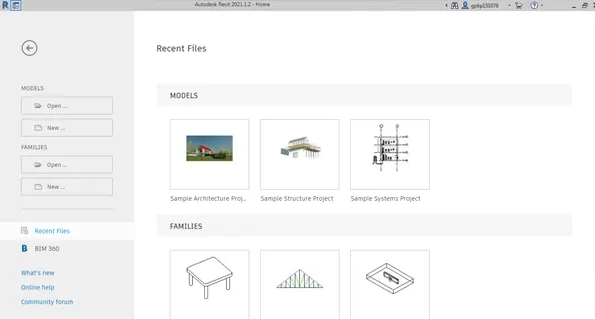
Step 2
- Click on > New from home page
- One dialogue box will open
- In that dialogue box > Click on dropdown
- Select template file as > Architectural Template as shown below
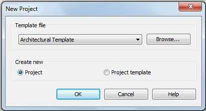
- Click > Ok
Step 3
- Click > File
- Click > Save
- One dialogue box will open
- Select file name > Archtectural Drawing

- Click on Save
- The result is ready
- Result :-
The file with name Architectural Drawing is created
Problem 2
- Aim :- To save the new project file and To close and open the file using file toolbar
- Procedure :-
Step 1
- Click on windows start
- In Search bar type > Revit
- Click > Revit 2021
- Once the revit is open, It will shows the following page
Step 2
- Click on > New from home page
- One dialogue box will open
- In that dialogue box > Click on dropdown
- Select template file as > Architectural Template as shown below
- Click > Ok
Step 3
- Click > File
- Click > Save
- One dialogue box will open
- Select file name > Archtectural Drawing
- Click on Save
- Close the file
- Click > File
- Click > Open
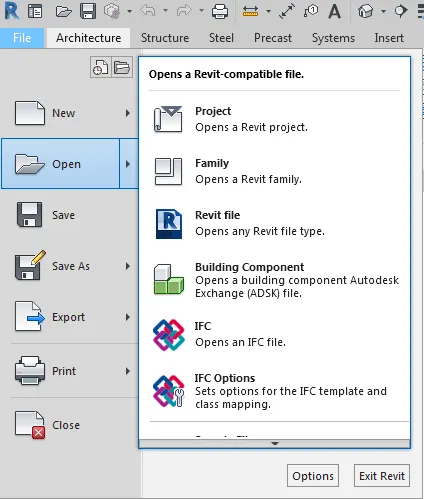
- After clicking on open, one dialogue box will open
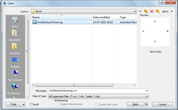
- Select the drawing by clicking the architectural drawing
- Click > Open
- The result is ready
- Result :-
The file with name Architectural Drawing is saved and opened by using the file toolbar
Problem 3
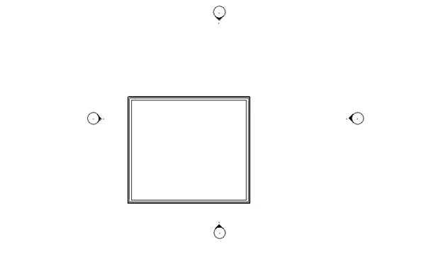
- Aim :- To create a rectangular layout of walls of about 40’-0” X 35’-0”
- Procedure :-
Step 1
- Click on windows start
- In Search bar type > Revit
- Click > Revit 2021
- Once the revit is open, It will shows the following page
Step 2
- Click on > New from home page
- One dialogue box will open
- In that dialogue box > Click on dropdown
- Select template file as > Architectural Template as shown below
- Click > Ok
Step 3
- Click > File
- Click > Save
- One dialogue box will open
- Select file name > Archtectural Drawing
- Click on Save
Step 4
- Click > Manage > Project unit
- Select length unit > Feet and fractional inches
- Click > Ok
- From the Architecture tab Click on dropdown below the wall
- Select > Architectural Wall
- Click > From where we have to start the wall
- Type 40’ > Enter by keeping curser rightside
- Type 35’ > Enter by keeping curser rightside
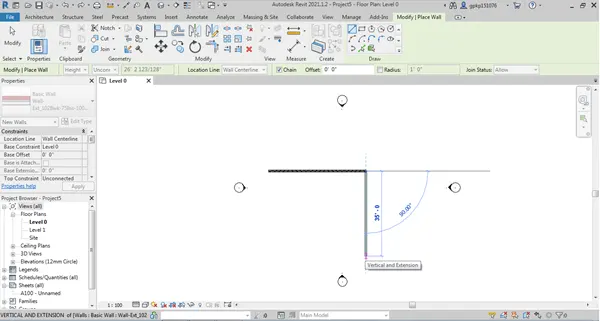
- Type 40’ > Enter by keeping curser lefttside
- Type 35’ > Enter by keeping curser uptside
- The wall is ready
- Result :-
Problem 4
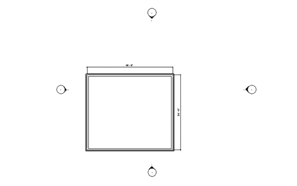
- Aim :- From the annotate toolbar use the aligned option to add dimensions to the layout
- Procedure :-
Step 1
- Click on windows start
- In Search bar type > Revit
- Click > Revit 2021
- Once the revit is open, It will shows the following page
Step 2
- Click on > New from home page
- One dialogue box will open
- In that dialogue box > Click on dropdown
- Select template file as > Architectural Template as shown below
- Click > Ok
Step 3
- Click > File
- Click > Save
- One dialogue box will open
- Select file name > Archtectural Drawing
- Click on Save
Step 4
- Click > Manage > Project unit
- Select length unit > Feet and fractional inches
- Click > Ok
- From the Architecture tab Click on dropdown below the wall
- Select > Architectural Wall
- Click > From where we have to start the wall
- Type 40’ > Enter by keeping curser rightside
- Type 35’ > Enter by keeping curser rightside
- Type 40’ > Enter by keeping curser lefttside
- Type 35’ > Enter by keeping curser uptside
- The wall is ready
Step 5
- Go to annotate tab
- Click on aligned dimensions
- Select the centre to centre distance
- Provide the required dimensions
- The result is ready
- Result :-
Problem 5
- Aim :- To use the properties browser to switch to different wall type
- Procedure :-
Step 1
- Click on windows start
- In Search bar type > Revit
- Click > Revit 2021
- Once the revit is open, It will shows the following page
Step 2
- Click on > New from home page
- One dialogue box will open
- In that dialogue box > Click on dropdown
- Select template file as > Architectural Template as shown below
- Click > Ok
Step 3
- Click > File
- Click > Save
- One dialogue box will open
- Select file name > Archtectural Drawing
- Click on Save
Step 4
- Click > Manage > Project unit
- Select length unit > Feet and fractional inches
- Click > Ok
- From the Architecture tab Click on dropdown below the wall
- Select > Architectural Wall
- Click > From where we have to start the wall
- Type 40’ > Enter by keeping curser rightside
- Type 35’ > Enter by keeping curser rightside
- Type 40’ > Enter by keeping curser lefttside
- Type 35’ > Enter by keeping curser uptside
- The wall is ready
Step 5
- Go to project browser
- Click > + Families
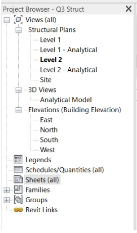
- Click > + Walls
- Click > +Basic Walls
- Select one of the wall
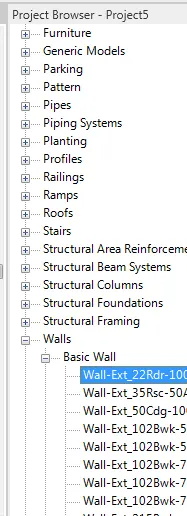
- Go to properties browser to change the wall type
- Select the type as shown below
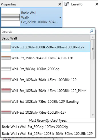
- Select the wall to change the type
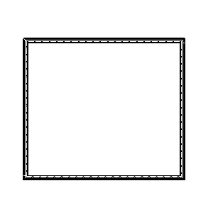
- The result is ready
- Result :-
Problem 6
- Aim :- To create the 3D view from the view toolbar and save the view with the appropriated name
- Procedure :-
Step 1
- Click on windows start
- In Search bar type > Revit
- Click > Revit 2021
- Once the revit is open, It will shows the following page
Step 2
- Click on > New from home page
- One dialogue box will open
- In that dialogue box > Click on dropdown
- Select template file as > Architectural Template as shown below
- Click > Ok
Step 3
- Click > File
- Click > Save
- One dialogue box will open
- Select file name > Archtectural Drawing
- Click on Save
Step 4
- Click > Manage > Project unit
- Select length unit > Feet and fractional inches
- Click > Ok
- From the Architecture tab Click on dropdown below the wall
- Select > Architectural Wall
- Click > From where we have to start the wall
- Type 40’ > Enter by keeping curser rightside
- Type 35’ > Enter by keeping curser rightside
- Type 40’ > Enter by keeping curser lefttside
- Type 35’ > Enter by keeping curser uptside
- The wall is ready
Step 5
- Go to annotate tab
- Click on aligned dimensions
- Select the centre to centre distance
- Provide the required dimensions
- The wall with dimensions is ready
Step 6
- Go to view tab
- Click on > Dropdown of 3D view
- Select > Default 3d View
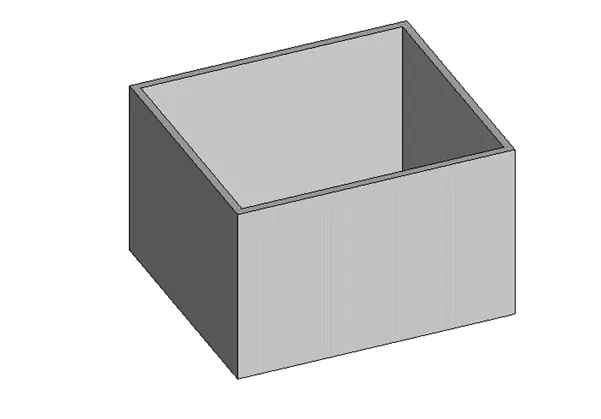
- The 3D view of wall is ready
- Go to project browser
- Click > + view
- Select > 3D view
- Rename the current view tab as > 3D wall view
- The result is ready
- Result :-
Problem 7
- Aim :- To navigate through the 3D model using the view cube. Orbit/pan through the model layout created
- Procedure :-
Step 1
- Click on windows start
- In Search bar type > Revit
- Click > Revit 2021
- Once the revit is open, It will shows the following page
Step 2
- Click on > New from home page
- One dialogue box will open
- In that dialogue box > Click on dropdown
- Select template file as > Architectural Template as shown below
- Click > Ok
Step 3
- Click > File
- Click > Save
- One dialogue box will open
- Select file name > Archtectural Drawing
- Click on Save
Step 4
- Click > Manage > Project unit
- Select length unit > Feet and fractional inches
- Click > Ok
- From the Architecture tab Click on dropdown below the wall
- Select > Architectural Wall
- Click > From where we have to start the wall
- Type 40’ > Enter by keeping curser rightside
- Type 35’ > Enter by keeping curser rightside
- Type 40’ > Enter by keeping curser lefttside
- Type 35’ > Enter by keeping curser uptside
- The wall is ready
Step 5
- Go to annotate tab
- Click on aligned dimensions
- Select the centre to centre distance
- Provide the required dimensions
- The wall with dimensions is ready
Step 6
- Go to view tab
- Click on > Dropdown of 3D view
- Select > Default 3d View
- The 3D view of wall is ready
- Go to project browser
- Click > + view
- Select > 3D view
- Rename the current view tab as > 3D wall view
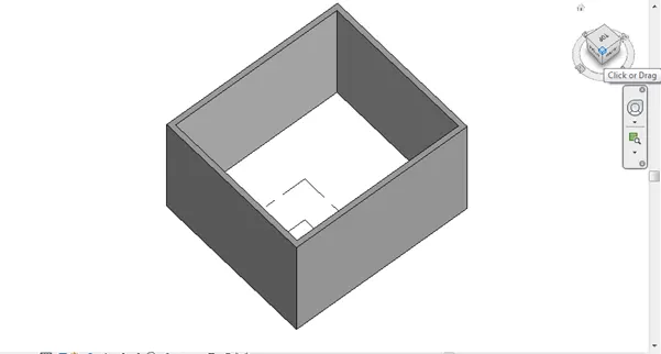
Step 7
- Nevigate through the view cube
- Change the view cube as per requirement
Step 8
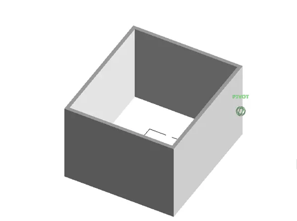
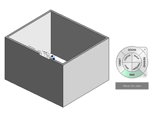
- Click on > Full navigation wheel
- Click > Orbit to start 3D orbit
- Click on > Pan to move
- The results are ready
- Result :-
Problem 8
- Aim :- To use the visibility setting option to switch model to shaded, realistic and hidden lines
- Procedure :-
Step 1
- Click on windows start
- In Search bar type > Revit
- Click > Revit 2021
- Once the revit is open, It will shows the following page
Step 2
- Click on > New from home page
- One dialogue box will open
- In that dialogue box > Click on dropdown
- Select template file as > Architectural Template as shown below
- Click > Ok
Step 3
- Click > File
- Click > Save
- One dialogue box will open
- Select file name > Archtectural Drawing
- Click on Save
Step 4
- Click > Manage > Project unit
- Select length unit > Feet and fractional inches
- Click > Ok
- From the Architecture tab Click on dropdown below the wall
- Select > Architectural Wall
- Click > From where we have to start the wall
- Type 40’ > Enter by keeping curser rightside
- Type 35’ > Enter by keeping curser rightside
- Type 40’ > Enter by keeping curser lefttside
- Type 35’ > Enter by keeping curser uptside
- The wall is ready
Step 5
- Go to annotate tab
- Click on aligned dimensions
- Select the centre to centre distance
- Provide the required dimensions
- The wall with dimensions is ready
Step 6
- Go to view tab
- Click on > Dropdown of 3D view
- Select > Default 3d View
- The 3D view of wall is ready
- Go to project browser
- Click > + view
- Select > 3D view
- Rename the current view tab as > 3D wall view
Step 7
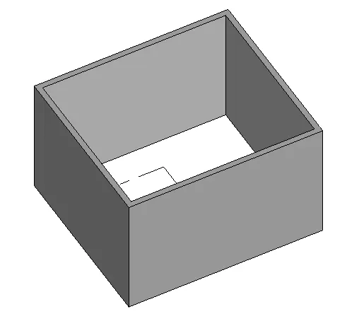
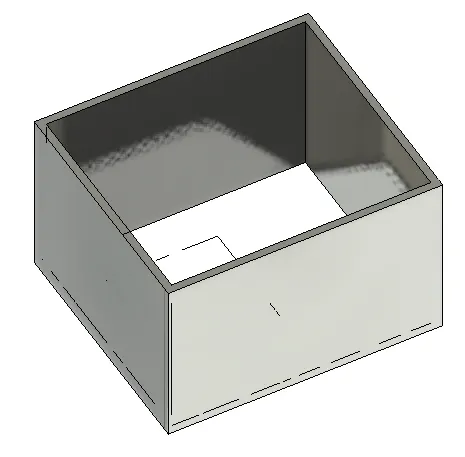
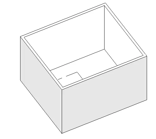
- Go to the visual style as per shown below
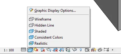
- Select the visual styles as per requirements
- The results are ready
- Result :-
- Shaded
- Realastic
- Hidden lines
Problem 9
- Aim :- To turn the sun path On and Off to view shadings in the layout created
- Procedure :-
Step 1
- Click on windows start
- In Search bar type > Revit
- Click > Revit 2021
- Once the revit is open, It will shows the following page
Step 2
- Click on > New from home page
- One dialogue box will open
- In that dialogue box > Click on dropdown
- Select template file as > Architectural Template as shown below
- Click > Ok
Step 3
- Click > File
- Click > Save
- One dialogue box will open
- Select file name > Archtectural Drawing
- Click on Save
Step 4
- Click > Manage > Project unit
- Select length unit > Feet and fractional inches
- Click > Ok
- From the Architecture tab Click on dropdown below the wall
- Select > Architectural Wall
- Click > From where we have to start the wall
- Type 40’ > Enter by keeping curser rightside
- Type 35’ > Enter by keeping curser rightside
- Type 40’ > Enter by keeping curser lefttside
- Type 35’ > Enter by keeping curser uptside
- The wall is ready
Step 5
- Go to annotate tab
- Click on aligned dimensions
- Select the centre to centre distance
- Provide the required dimensions
- The wall with dimensions is ready
Step 6
- Go to view tab
- Click on > Dropdown of 3D view
- Select > Default 3d View
- The 3D view of wall is ready
- Go to project browser
- Click > + view
- Select > 3D view
- Rename the current view tab as > 3D wall view
- The 3D wall view is ready
Step 7
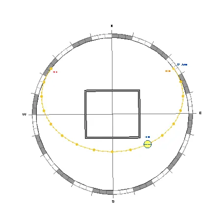
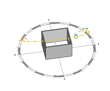
- Currently, the sun path is in off condition
- To make it on
- Go to the bottom toolbar
- Click on > Sunpath
- Click > sun setting
- One dialogue box will open
- Set the location, time and date as per requirement
- Make the sunpath > On
- Take the top view using the view cube
- The results are ready
- Result :-
Problem 10
- Aim :- To use the manage toolbar to enter project setting, project name and project issue date
- Procedure :-
Step 1
- Click on windows start
- In Search bar type > Revit
- Click > Revit 2021
- Once the revit is open, It will shows the following page
Step 2
- Click on > New from home page
- One dialogue box will open
- In that dialogue box > Click on dropdown
- Select template file as > Architectural Template as shown below
- Click > Ok
Step 3
- Click > File
- Click > Save
- One dialogue box will open
- Select file name > Archtectural Drawing
- Click on Save
Step 4
- Click > Manage > Project unit
- Select length unit > Feet and fractional inches
- Click > Ok
- From the Architecture tab Click on dropdown below the wall
- Select > Architectural Wall
- Click > From where we have to start the wall
- Type 40’ > Enter by keeping curser rightside
- Type 35’ > Enter by keeping curser rightside
- Type 40’ > Enter by keeping curser lefttside
- Type 35’ > Enter by keeping curser uptside
- The wall is ready
Step 5
- Go to annotate tab
- Click on aligned dimensions
- Select the centre to centre distance
- Provide the required dimensions
- The wall with dimensions is ready
Step 6
- Go to view tab
- Click on > Dropdown of 3D view
- Select > Default 3d View
- The 3D view of wall is ready
- Go to project browser
- Click > + view
- Select > 3D view
- Rename the current view tab as > 3D wall view
- The 3D view is ready
Step 7
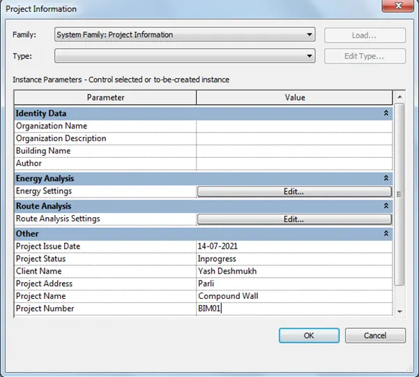
- Go to manage tab
- Click > Project information
- One dialogue box will open

- Fill the required data as per shown in result
- Result :-
Problem 11
- Aim :- To know the use of analyze toolbar and to know, how it is beneficial for design and modelling

- It contains tool to adjust the analytical model, check for consistency, reseat the model and check member supports in this tab.
- The toolbar is used to create the saperators.
- We can add the boundry conditions and types of loads.
- We can edit the load cases.
- We can add the load combinations.
- Many types of reports such as Heating and cooling load reports, panel reports etc are prepared.
- Distance and time of travel from one end to another end can be calculated.
- We can understand, how sustainable and energy efficient the building is.
- It also helps to perform energy optimisation and energy analysis.
- We can achieve the progress of project together from all disciplines.
Problem 12
- Aim :- To know links that revit supports to be linked to the model
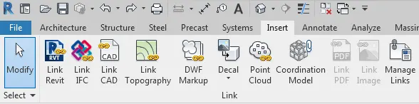
- In insert tab, we will get the links
- Link Revit – It allows to link another revit model to the current model
- Link IFC – It allows to link IFC File as a reference, when we want to perform additional design work in revit.
- Link CAD – It allows to link the CAD file. To create 3D using rivet, we can link the cad file having 2D drawing
- Link Topography – It allows to link the existing topography to the current model
Problem 13
- Aim :- To know the needs of collaborate tab in the revit and how it supports the modelling and its efficiency

- It is one of the feature, which helps the team members to work on a single model simultaneously.
- We do not have wait for one model to be completed to start the model of the next discipline.
- e.g. : If a mechanical and structural engineers wants to in a model simultaneously, the collaborate option creates a central file and we will have the facility to create the multiple files that enables collaboration.
- We can link multiple revit models together, allowing team members to work in context.
- When collaboration needs to occur among users who are not in same geographic location, use revit server or Revit Cloud Work-Shairing.
- The efficiency of the modelling will be high as the work can be finish faster.