Introduction to REVIT concepts
AIM :- Create a new project (Structural / Architectural / Construction template) and name the project.
PROCEDURE :-
- Open Revit software
- After this click on new
- Then click on ARCHITECTURAL TEMPLATE then project okay
- Then now click on Revit icon then option save okay
- Then type file name and save in any location where you want
RESULT :-
- Template file is saved at the desktop name as revit ch.1 Q1.

AIM :- To save the new file. Close and open using icon from file toolbar.
PROCEDURE :-
- Open Revit software
- After this click on new
- Then click on ARCHITECTURAL TEMPLATE then project okay
- Then now click on Revit icon then option save okay
- Then type file name and save in any location where you want
- Now click on file tab
- Then click open and select revit ch.1 Q1
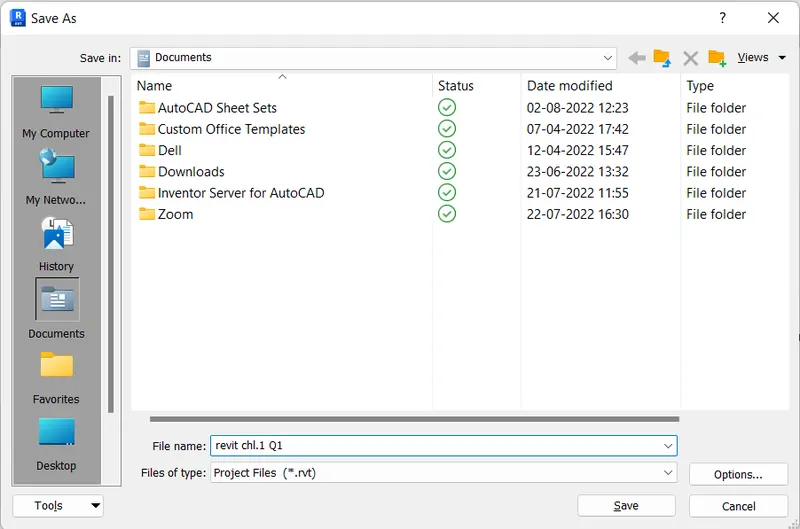
RESULT :-
- Template file is saved at the desktop name as revit ch.1 Q1.
- And reopped by using file tab.

AIM :- To create a architectural/structural toolbar familiarize with options to draw a wall of rectangular layout of wall of about 40’0”x35’0”.
PROCEDURE :-
- Open Revit software
- Now click on file tab
- Then click open and select revit ch.1 Q1
- Select the wall icon from architectural tool bar
- Using wall icon draw a rectangle of 40’ & 35’ layout of wall
RESULT :-
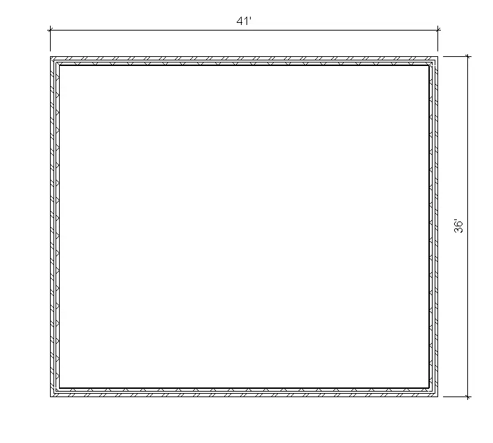
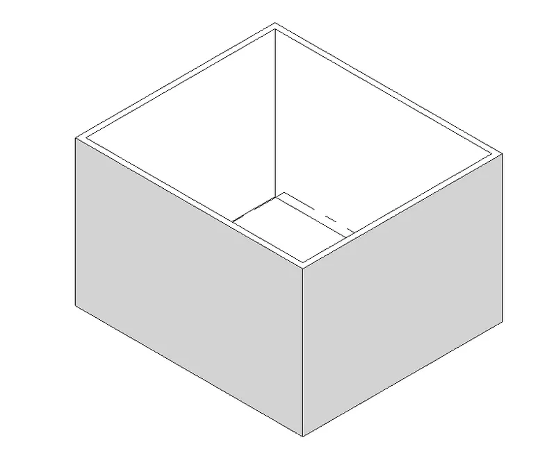
- The wall layout of 40’x35’ is created by using tabs over there.
AIM :- From the annotate toolbar use the aligned option to add dimensions to the layout.
PROCEDURE :-
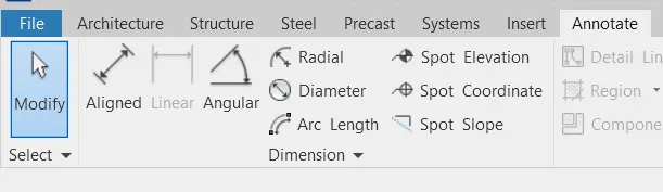
- Click on annotate toolbar
- Select aligned and click on layout for dimensions
RESULT :-
- The dimensions of layout are shown by using the annotate toolbar.
AIM :- Use the properties browser to switch to different wall types.
PROCEDURE :-
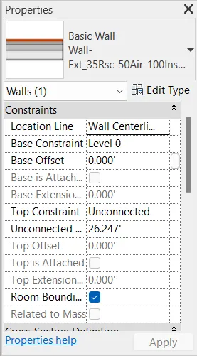
- Create a wall by using the wall icon
- Click on the drawing
- Now modify change different walls
RESULT :-
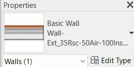
- By using properties browser the wall properties are changed.
AIM :- Create a 3D view from the view toolbar and save the view with the appropriate name.
PROCEDURE :-
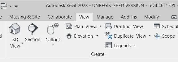
- Go to the view tab click on the 3D view
- Right click on the view cube
- And select save and name as view 1
RESULT :-
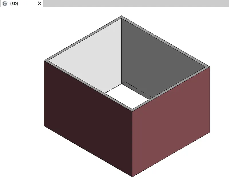
- The 3D view of wall is saved by using the view cube.
AIM :- Navigate through the 3D model using the view cube. Orbit/plan through the model layout created.
PROCEDURE :-
- Click on the panel / view orbit
- Now navigate through the 3D model which side you want
- And from which direction you want to watch the model
RESULT :-
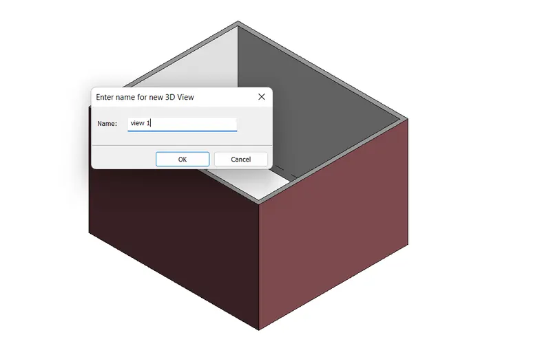
- Navigated the model by using the view cube/orbit.
AIM :- Use the visibility setting option below to switch model to shaded, realistic, hidden lines option.
PROCEDURE :-
- Click on the visibility section which is in the below tab
- Visibility style >shaded
- Visibility style > realistic
- Visibility style > hidden
- Accordingly one by one choose the options
RESULT :-
- Here are the shown the visibility styles one by one
- Visibility style >shaded
- Visibility style > realistic
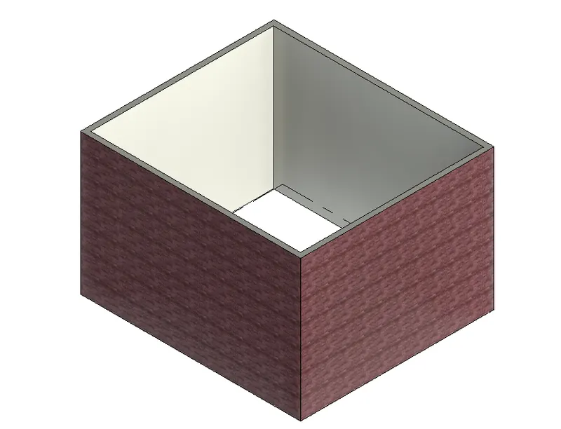
- Visibility style > hidden
AIM :- Turn the sun path on and off to view shadings in the layout created.
PROCEDURE :-
- Click on sunlight on & off in the below bar
RESULT :-
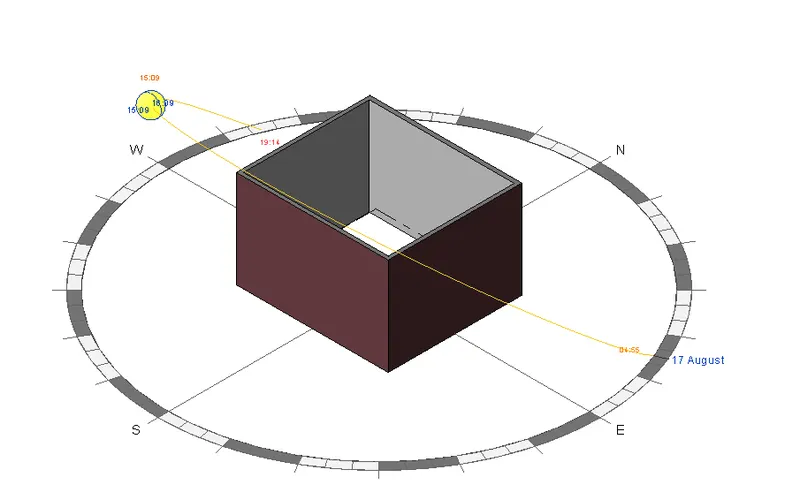
- Used the sunlight on & off option below in ribbon.
AIM :- Use the manage toolbar to enter project settings, project name and project issue date ( choose according to yours ).
PROCEDURE :-
- Click on manage toolbar then project information
RESULT :-
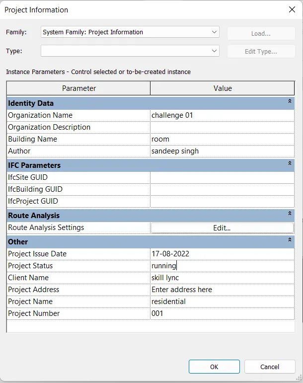
- Manage toolbar is used to make changes accordingly
- And for entering data what it requireds.
- Analyse toolbar is used to inform solutions during the design. We can also analyse the conceptual design in several ways and we can also rectify errors by using the analyse toolbar. It allows to check our structure within the software Revit.
- Revit Links supports the use of view templates. When you use Revit LT to open a Revit project, view template settings for filters, work sets and RVT links apply even though they are not normally supported by Revit Links some of the links are Revit , IFC ( an IFC is a model file format used by building information modelling (BIM) programs. It contains a model of building or facility, including special elements, materials and shapes) CAD drawings and DWF markup,
- Collaborate tab enables collaboration so team members can work on a model simultaneously. It provides several ways to share project to work or information with other team.