Introduction to REVIT concepts
1)TO create a new project and name the project appropriately from the menu TOOLS/COMMANDS USED
- Mouse Whee
- Properties polette
- File Menu
- Open
PROCEDURE
STEP 1: First open revit software
STEP2: NOw click on file option which is at top lett corner
STEP-3:Next select on new option
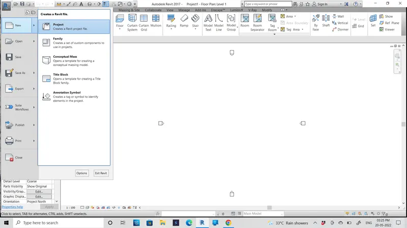
STEP 4:Now select project Option
STEP 5:After selecting project acidlog box of new project appears.Click the drop box under template file and select
the template required for project
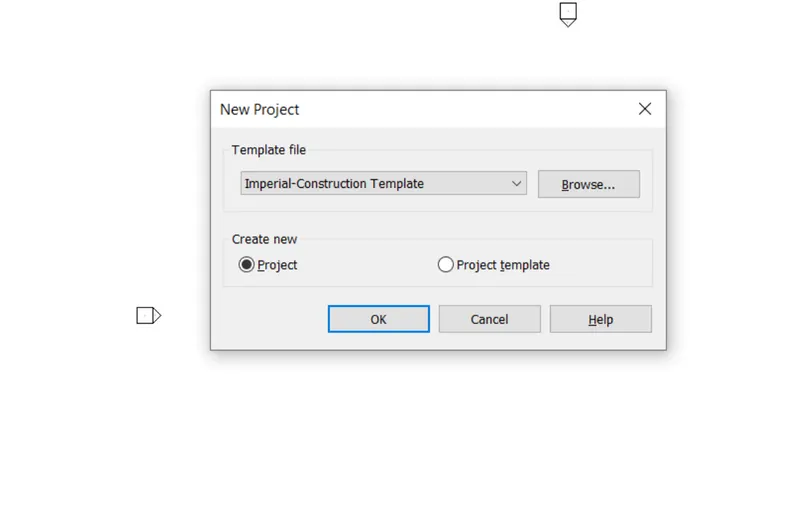
STEP 6:Click ok
STEP-7: new project name is created
STEP-8:Now go to properties palatte and select the view option and name the project as PROJECT-1.
STEP-9: CIick opply
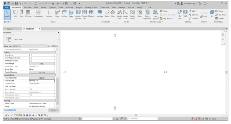
STEP-10:File náme is named as PROJECT
STEP-11:Follow similar method for architectural template and construction template and name them as requirea.
RESULT:
New project (structural/architectural) created successtully by above procedure and named
architectural template as PROJECTH 1
2) Save the new project file. Close and open using icons from file toolbar
AIM:TO save the new project file.close and open the file
COMMANDS AND TOOLS USED:
- MOUSE WHEEL
- FILE MENU
- SAVE
- NEW PROJECT
PROCEDURE:
STEP-1:Select the file tool which is at the top left cormer
STEP-2:click on save option.
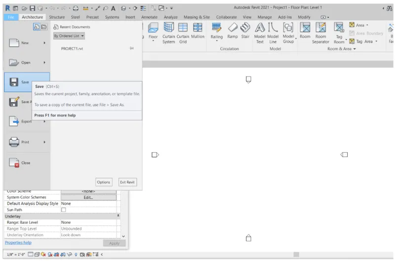

step 4 : new project saved as REVIT PROJECT in specified place
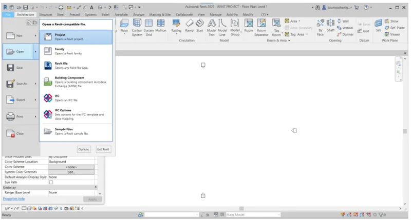
step 5: now select file tab click on open then open project
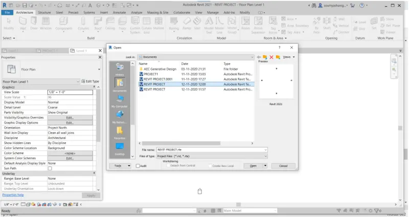
step 6: select REVIT PROJECT and open the file
step 7: close the revit project
Result :
new project created successfully and Save the new project file. Close and open using icons from file toolbar
3)
Aim : draw a wall. Create a rectangular layout of walls of about 40’-0” X 35’-0”
TOOLS/COMMEND USED :
- WALL
- ARCHITECTURE
Procedure:
step 1: select wall icon select wall architectural
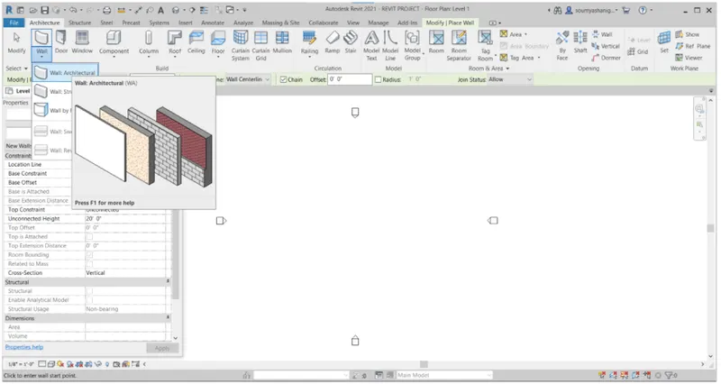
step 2 :
then draw rectangular layout of 40'x35' in such a way that draw a line of 40' along x- axis press enter and move cursor along y axis a nd draw a line of 35' press enter and then move cursor along x - axis of 40' press y- axis of 35' press enter.
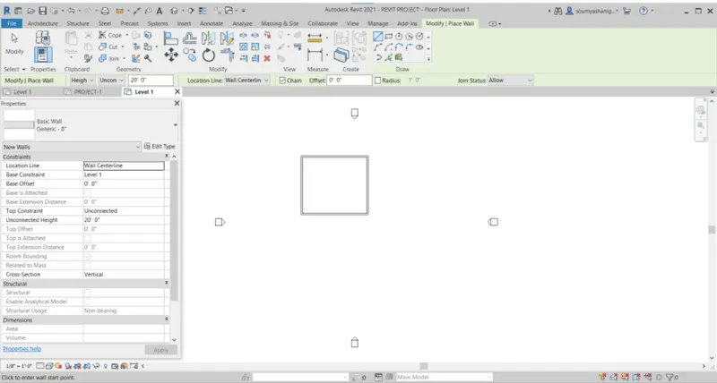
result :Created a rectangular layout of walls of about 40’-0” X 35’-0”
4)
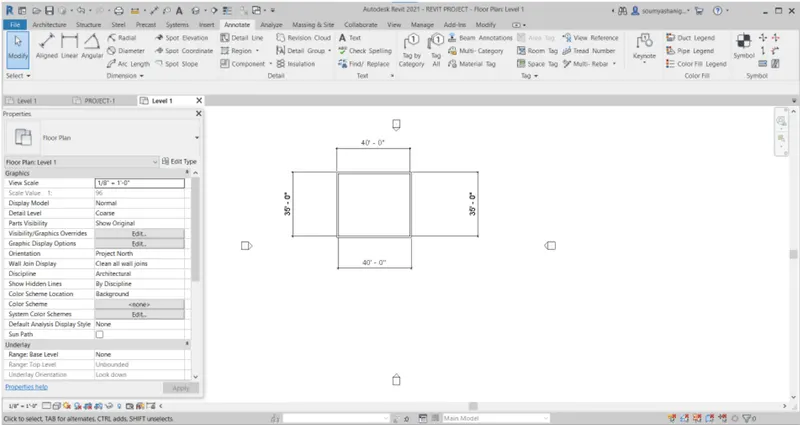
aim: Annotate toolbar use the aligned option to add dimensions to the layout
TOOLS/COMMEND USED :
- Annotate toolbar
- aligned
procedure:
step 1: chose annotate tab
step 2: click on aligned option
step 3: select the wall one end to another end click enter
5)
aim : Use the properties browser to switch to different wall types
TOOLS/COMMEND USED :
- Properties broser
procedure:
step 1: select rectangular wall
step 2: click on propertie browser wher one can different wall types.
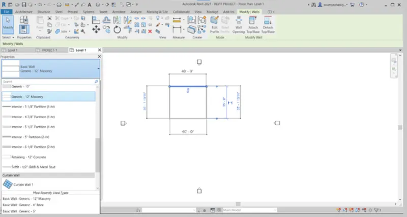
result : successefully changed from generic 8'' - 12'' wall view by properties browser.
6)
aim: Create a 3D view from the view toolbar and save the view with the appropriate name
TOOLS/COMMEND USED :
- view toll bar
- properties pallatte
- 3d view
- defult 3d view
procedure:
step 1: creat model
step 2: select view tollbar
step 3: select the 3d view and choose defult 3d view option
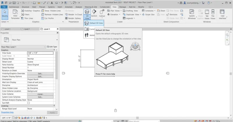
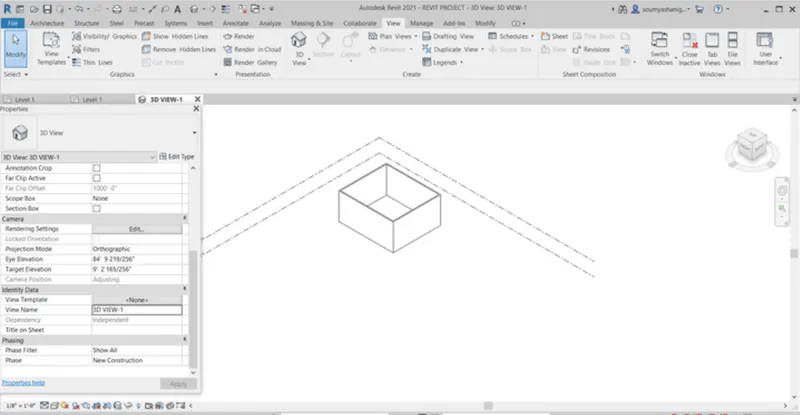
result : Created a 3D view from the view toolbar and save the view with the appropriate name
7) Navigate through the 3D model using the view cube. Orbit/pan through the model layout created
Aim: To Navigate through the 3D model using the view cube. Orbit/pan through the model layou created
introduction: once a 3D model is created, we can navigate through the model using view cube, which is
changinig to difterent vievws such as top, right. front, etc. and also Isometric views. Using Orbit /Pan we can
also get the view that is most appealing to us when the standard view is not appealing
Procedure
Step 1: Open REVIT, Click the windows button and type REMIT end press enter
Step 2: Open any drawings Open any drawing ereated in auestion 3le 03 Struct
Step 3: Ndvigationtheugh View
Open the 3D Vieweteated above 3D isometric
From vieWehangedifferent to different views as per requirement
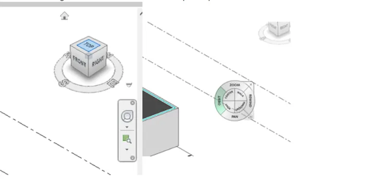
step 4: orbit/plan
using a full navigation wheel we can orbit/pan as shown below
click on-orbit to start 3d orbit
click on pan to move through model space
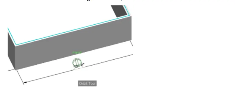
Result : the main aim of the challenge is to navigate throuh the 3d view of the wall. initially wall layout drawing of 40'x35' openeed in Revit Navigation through a view is done using a view cube. orbit pan is done through the full navigation wheel
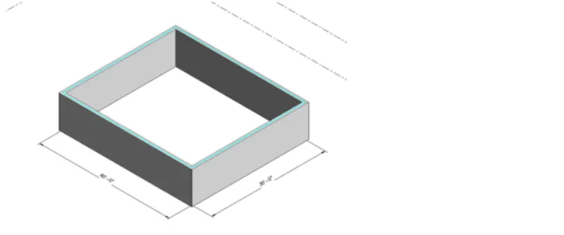
8) Use the visibility settings option below to switch model to shaded, realistic, hidden lines options
Aim: To switch model view to shaded, realistic, and hidden lines options using visibility setings
Introduction:
Once a 3D model is created, we create a 2D wireframe model, which is e fransparent model with lines
which is not aesthetic if many wals and components are presenf seitis recommended to change the
visibility of 3D to make the lines on the back hidden or shade the wall for abetter view
Procedure
Step 1: Open REVIT
Click the windows button and type REVIT and press enter
Step 2: Open a drawing
Open drawing created in question 31.c. 03 Struct.
Step 3: Changing Visibility Settings
Open the 3D view created above 1.0 3D isometric
Go to the bottom toolbar and click on visual settings as shownin
Change to respective views as required
Views are shown in the result
- Hidden line
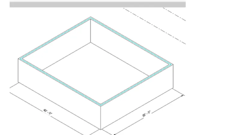
- shaded view
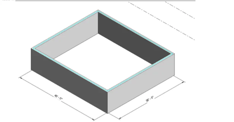
- realistic view
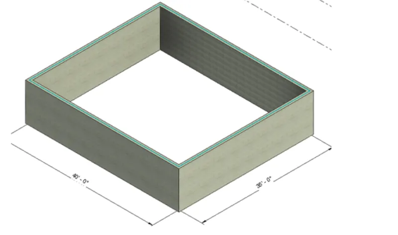
9) Turn the sun path on and off to view shadings in the layout created
Aim: To Turn the sun path on
and off to view shadings in the layout created
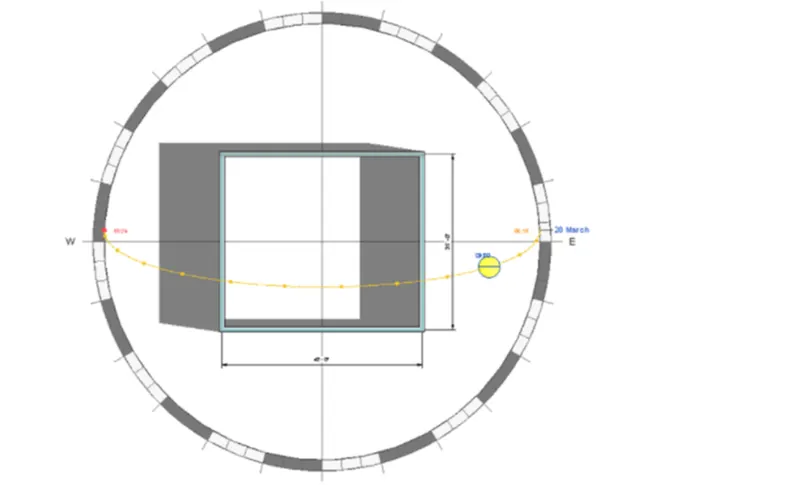
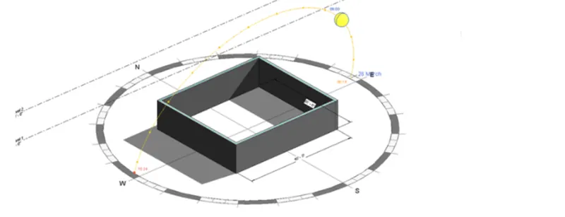
Introduction:Oncea 3D model is created, we create a 2D Wirefre shadows and shadings of 3D views. Sun path is generally fromegst location affect the shadows formed. In Revit, we can give the loo path decides the time of the day and time to give an exact sun path to the view.
Procedure:
Step 1: Open REVIT and Open Drawing
As per previous questions REVIT is opened and the Drewing
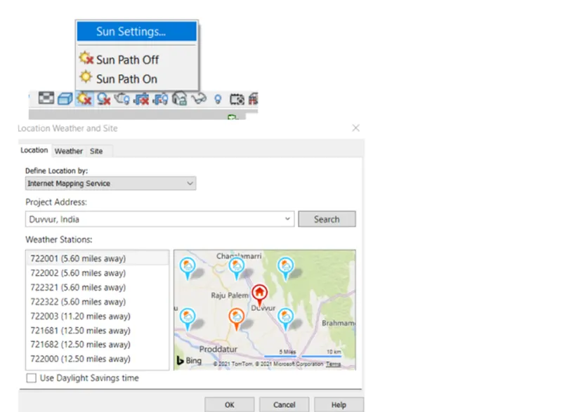
3D ISometric view is opened Click on the sun symbol to open sun settings as shown below
Step 2: Creating Sun path go to the bottom tool bar
From dialogue bOx, click on three dots adjacent to location Set the location as per our requirement, Click OK to confirm the location: Set Preset as Summer Solstice Time as 10 AM Click on APPLY and Click on OK to set the location
Turn on the SUN path at the Bottom tool pan
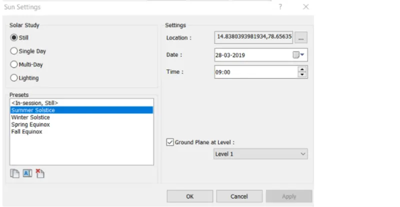
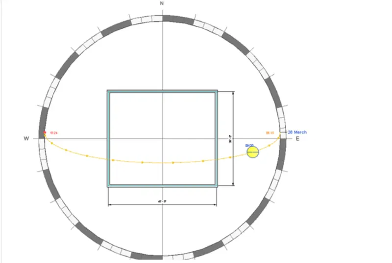
Result : main aim of hallenge is turn on the sun path and of the view shadings in the layout created. initially wall layout created. initially wall layout 40'x30' opened in Revit file. sun path is created when what location is required
- top view
- adjusted view
10) Use the Manage toolbar to enter project settings, project name, and project issue date (choose according to your convenience).
AIM : enter project settings, project name, and project issue date
Procedure:
STEP1: First click on the manage tool bar to open manage tool bar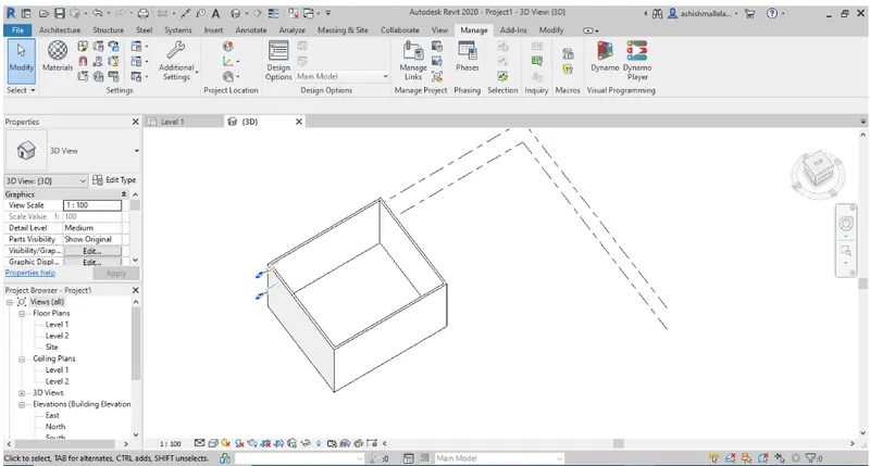
step 2: now we will find the project information icon under the setting manage tool bar
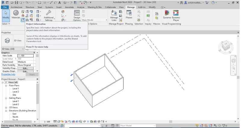
step 3: by clicking the project information tool, a box is opend and we can enter the name,enter the date and also can change the project setting
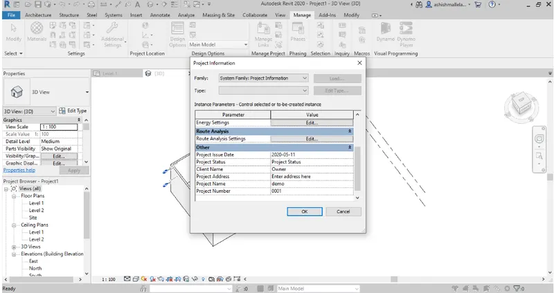
RESULT : enter project settings, project name, and project issue date comleted
11)What is the Analyze toolbar used in Revit? How it is beneficial for design and modeling
Andlyse tool bar helps in creating revit models, this tool bar consists of many other options which help in to load
combinations, boundary conditions, loads and support system are one among the tools under this andlyze tool bar
where we get to adjust the model and add additional supports to the present model, it also veifies the analytical
and physical model for the consistency. Space seperation, naming and tagging are dlso the options available
assigning the names and numbers to the architectural rooms. Colour fill and energy optimization are the tools which
help to know how far the present model is eco friendly.
12.
Links that support revit to link models are
- Link revit
- Link IFc
- Link CAD
- Link tropography
- DWF markup
- Coordination model
- link pdf
- link image
13)
We useCollaborate Tab To link up multiple rivet models together i.e if any member among a particular team can have acces to do any change required,which.js very useful when a team consists different cader of people working around that is for a steel designer to a Interior design engineer. This helps people there to work with higher accuracy which will increase the efficiency.