Creating a Floor plan, Footing detail and Isometric view using AutoCad
AIM : creating a floor plan, footing detail and isometric view using Autocad
step by step procedure used to draft the image
- Click Home tab > Draw panel > Line. Find.
- Specify the start point and end point of the line segment by clicking in the drawing area.
- Continue specifying additional line segments. ...
- Press Enter or Esc when done or enter c to close a series of line segments.
- final finishing drawimg measure the distance
- labelling
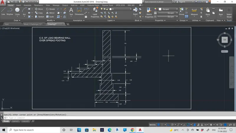
1)cross section of bearing wall over spread footing
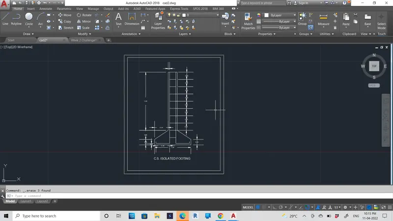
2) CROSS SECTION ISOLATED FOOTING
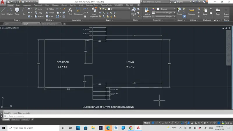
3) LINE DIAGRAM OF TWO BEDROOM BUILDING
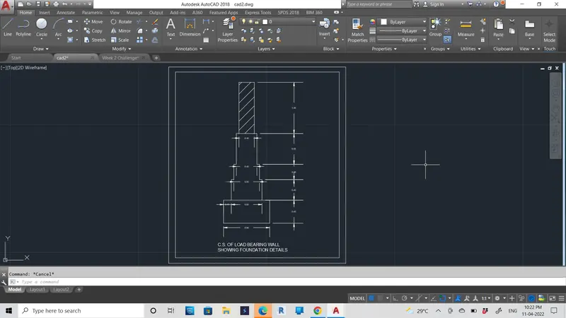
4)CROSS SECTION OF LOAD BEARING WALL SHOWING FOUNDATION DETAILS
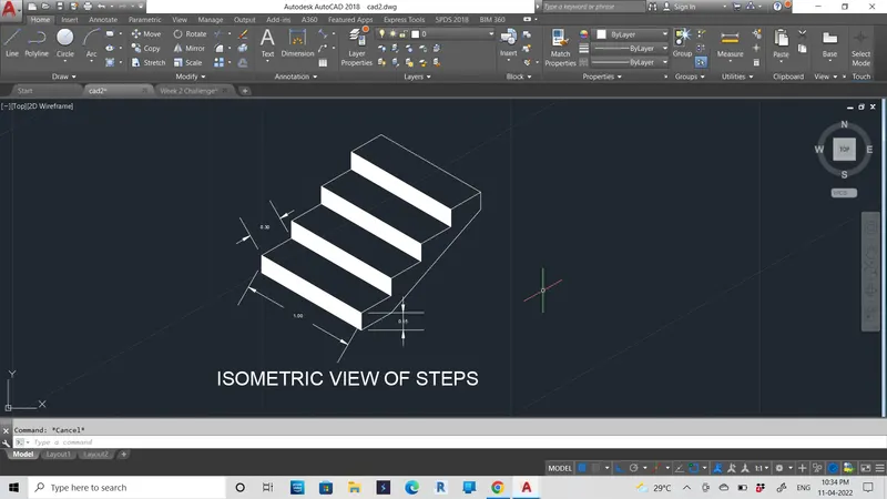
5) ISOMETRIC VIEW OF STEPS
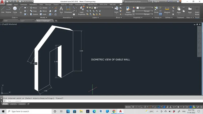
6) ISOMETRIC VIEW OF GABLE WALL