Introduction to REVIT concepts
1) Aim: To create a new project either structural, architectural or construction template using revit 2017 software
Procedure:
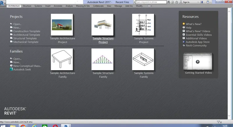
Go to startmenu and double click on the revit 2017 software and the revit software opens
The below page will appears after opening the revit software
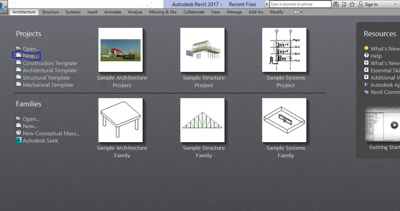
There is a otion called new option click on that option
New project dialogue box opens once we click on the new option
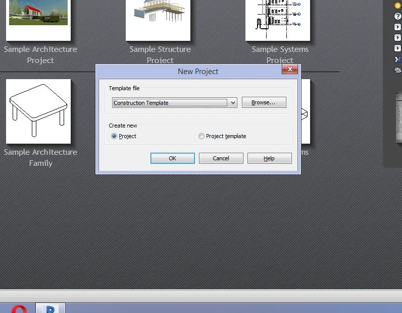
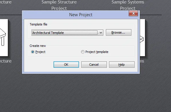
Then open a either architectural, structural or construction template in template file option
And select architectural template file and then click ok
And the revit screen wil appear
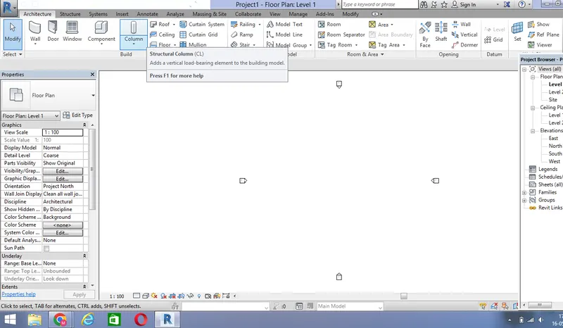
Then go to file menu and select the save option and choose the destination file and rename the drawing as Revit challenge 1 and click on save option
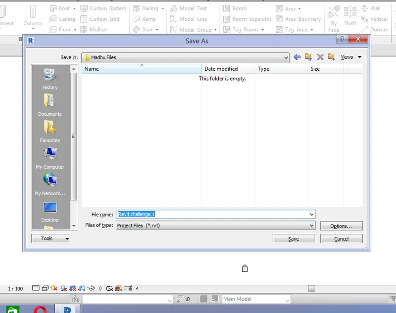
2) The file had already been saved in previous question and once again save the file using new menu bar and save the file using save option
Go to file menu and choose the close option and close the file
After pressing close option this page will occur
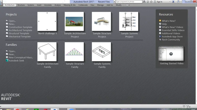
And once again open the file using this icon
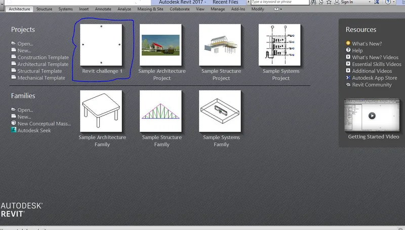
Click on that icon to open the file and the file opens
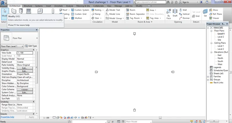
3) Aim: To draw a rectangle layout of size 40'X35' using revit software
Procedure:
Open the revit software and we had already opened a architectural template
To draw a wall, under the architectural tab we have the option called wall
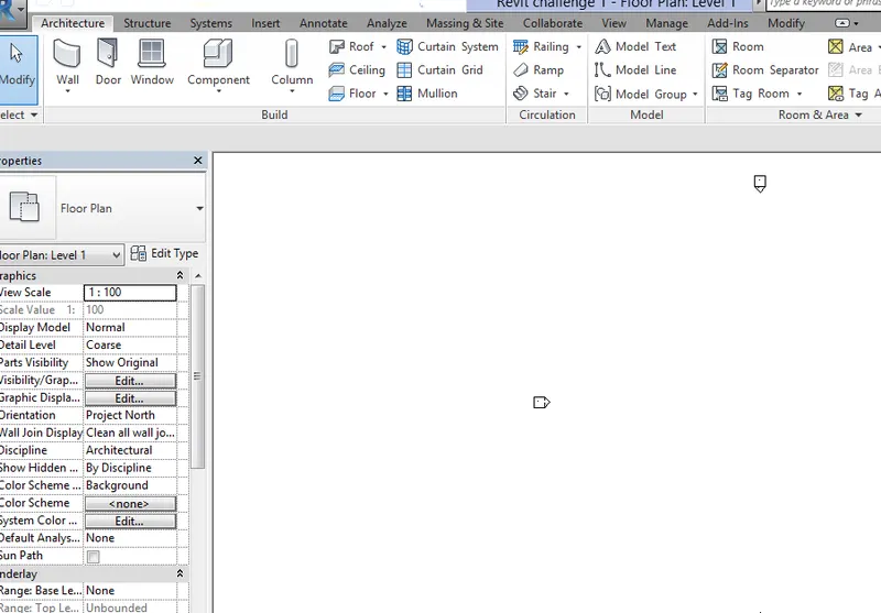
Click on that architectural wall and we have many options to draw a wall using those options we can draw a wall in the draw tab
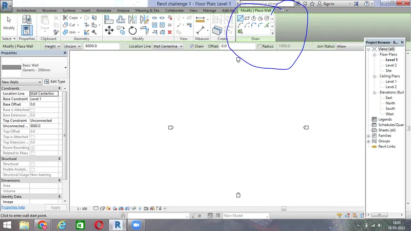
We have to choose line option to draw a wall
Take A horizontal length as 40' using line option and press enter
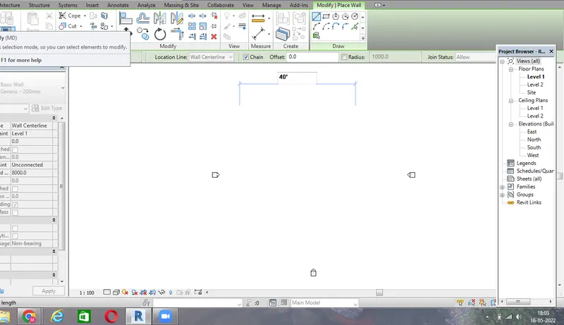
And then vertically 35' and press enter
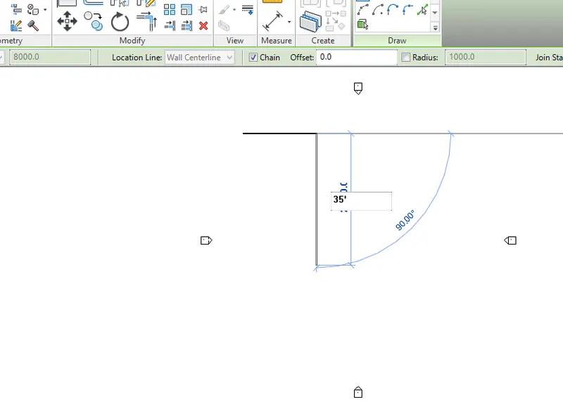
And again horizontally 40' and press enter
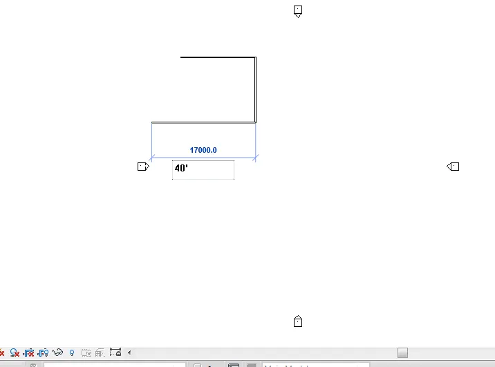
And again 35' in vertical direction
And like this we have to create a wall using architectural wall command
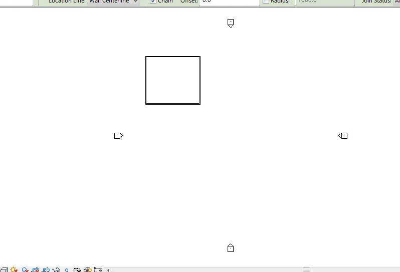
4) Aim: To add the dimensions to the wall which we had already created
Open the revit software, we had already created a rectangular layout using wall option under the architectural tab
For this rectangular layout we have to give the dimensions using annotate tab
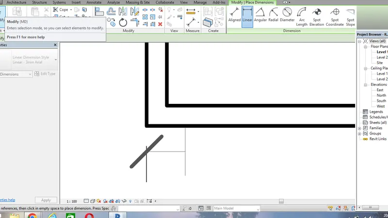
Click on the annotate tab and we have three option like linear, aligned and angular type of dimensions
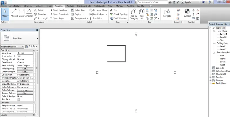
Choose any one of these either linear or alligned dimensions
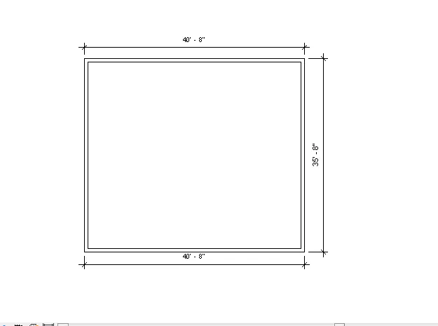
Choose the linear dimensions and carefully click the corner of the wall
Select from one corner point to the other corner point
Similarly dimension in the vertical direction also
5) Aim: Using a property browser to switch to the different walls
Open the revit software and the wall is already been created in our last question
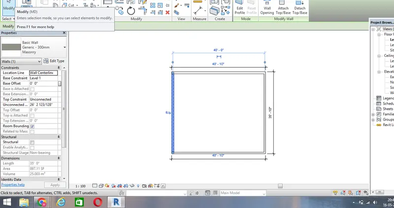
Click on any wall and go to property browser
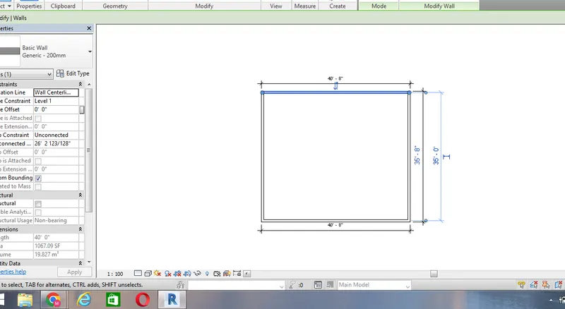
This wall is in generic 200mm wall to change this wall into another thickness of a wall go to property browser and select the type of wall
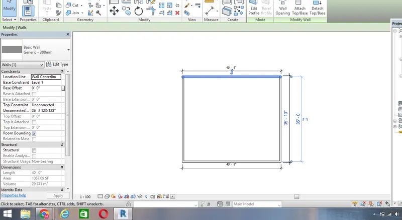
So that the wall is changed from 200mm to generic 300mm wall
Similarly change the wall type for different walls
6) Aim: To create a 3D view and save the view with appropriate name
Open the revit software and we had already created a floorplan layout
To switch the normal floor plan view to 3D view we have one option called as default 3D view on the top of our revit software
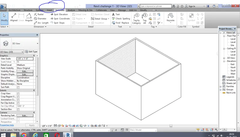
By clicking on the default 3D view, it is changed to 3D view
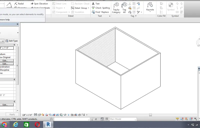
This is one view if we want to change to another views press on view cube
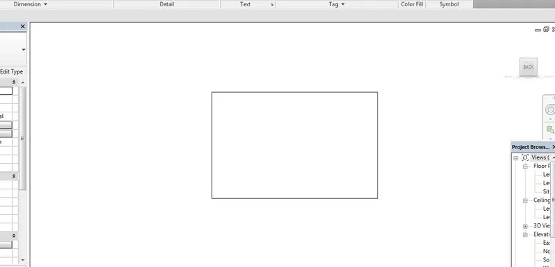
Click on view cube and right click on view cube and save the views in different names
Now this model is in the right view and by right clicking on the view cube we can save the views in different names
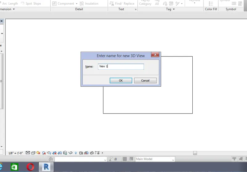
Similarly go to top view and right click on that view and save the name as view 2
And similarly for other views click on that view and right click on that and save the views
And by clicking arrows in the view cube we can rotate the views wherever we want to rotate
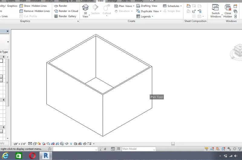
7) Aim: To use the orbit/pan tool using the navigation bar in the 3D view
Open the revit software and we have rectangular layout which we had already created in previous questions
Go to view tab and select the user interface option and click on the navigation bar
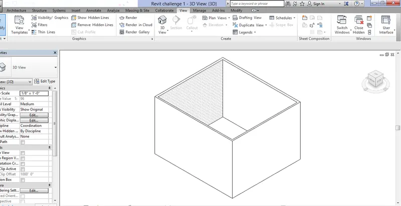
And the navigation bar appears in the right corner of the screen
Press on the navigation bar and the circular tab will appear in which it consists of a orbit tool, pan tool, zoom tool
Click on the orbit tool and press and orbit the model
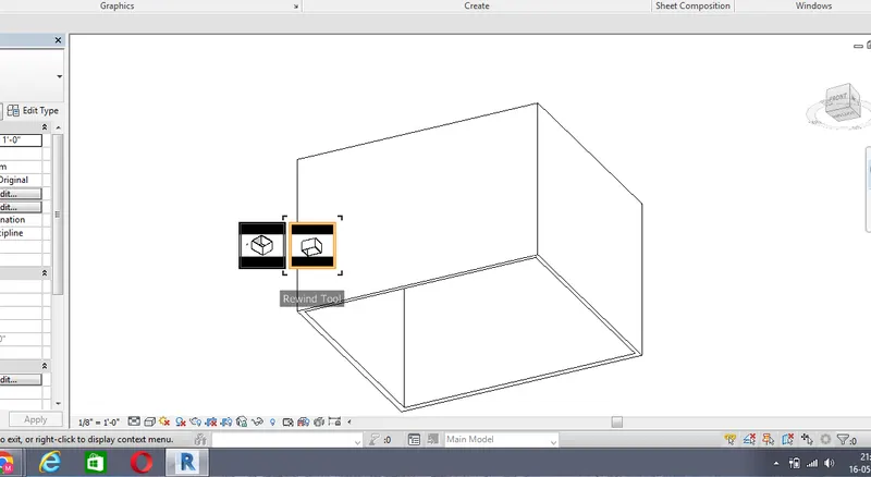
And there is another option called zoom tool and click on that zoom tool and zoom in and zoom out using this tool
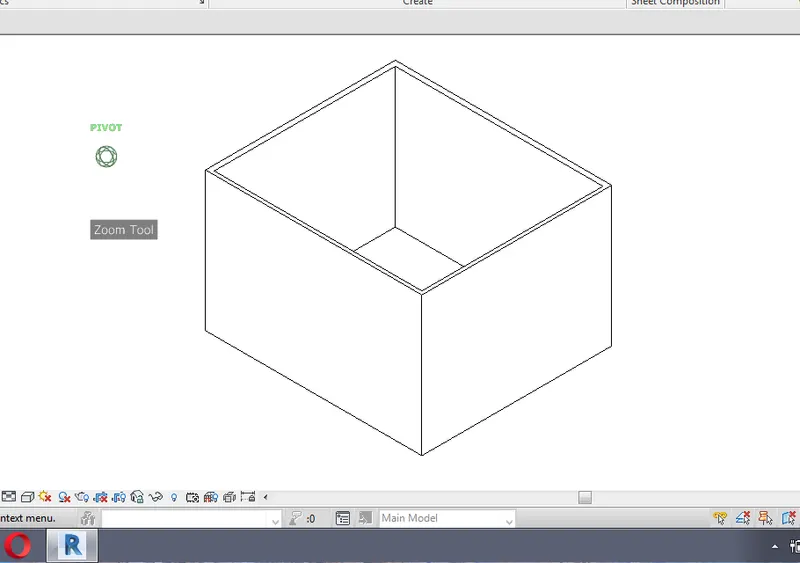
And click on the pan tool to pan the 3d model using pan tool
8) Aim: To switch the model to shaded view, realistic view and hidden lines using visibility settings
Open the revit software and we already created a rectangular layout and Open the 3d view of the created rectangular layout
To make the realistic view or shaded view, we have a option called visual style in the bottom tool bar
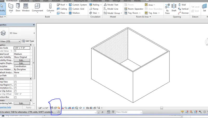
In this option we have shaded view, realistic view
Using this option we can easily switch the visuality settings from realistic to shaded or shaded to wireframe etc
If we switch this model into realistic view it will appears like this type
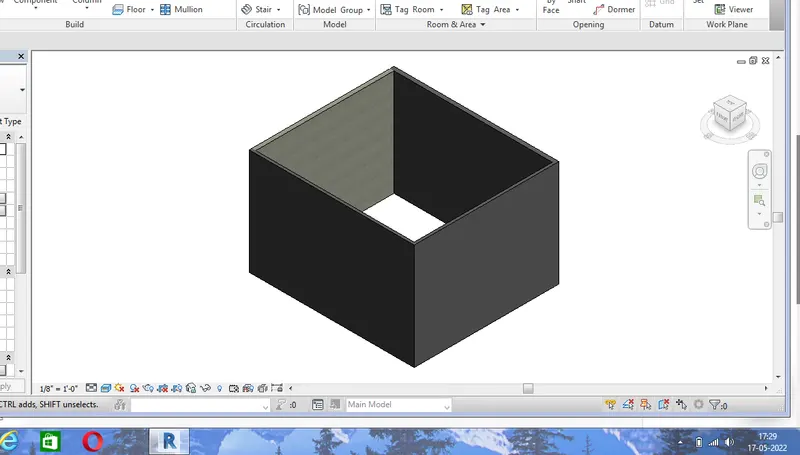
If we switch to the shaded view the model wil appear like this
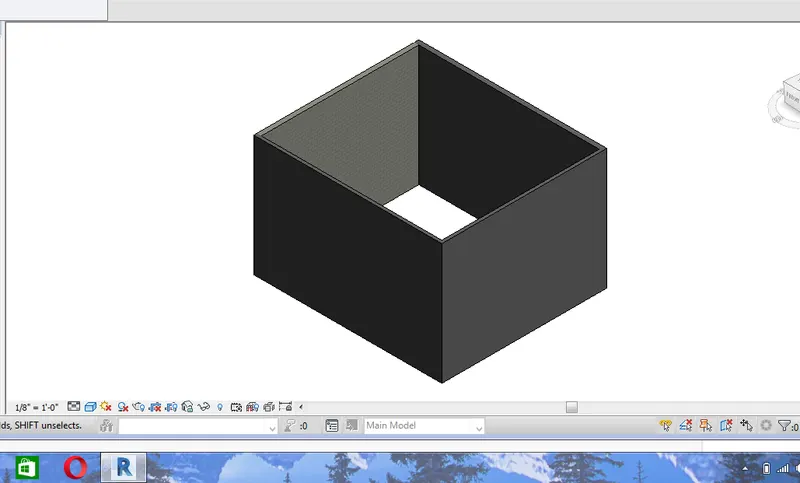
If we switch this model into Wireframe model this type of model will appear
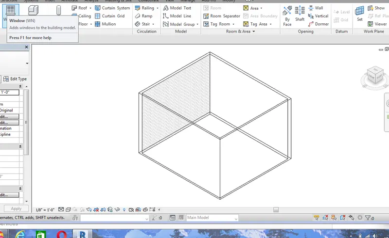
Similarly like this, we can switch to different views using visual style option
9) Aim: To Turn on or turn off the sun path to view shadings using the layout created
Open the revit software and we had already a rectangular layout and it is in 3D view
If we want to turn on the sunlight, we have a dedicated option in the bottom tool bar called sun path off or sun path on
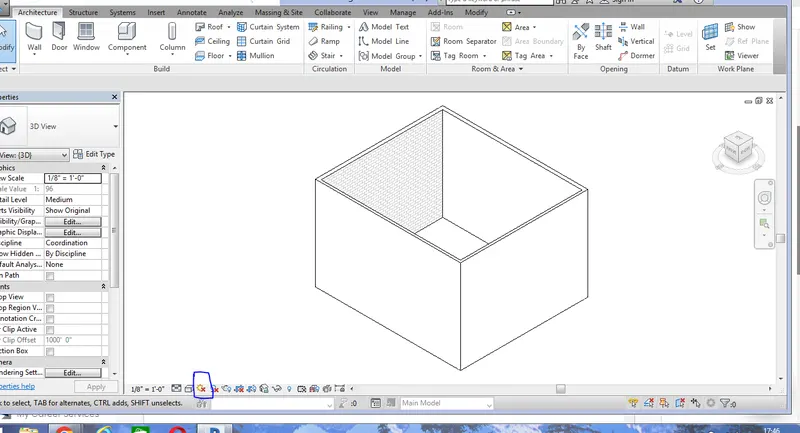
There we can off or on the sun path using this option
Turn on the sun path and one dialogue box appears and select continue with current settings
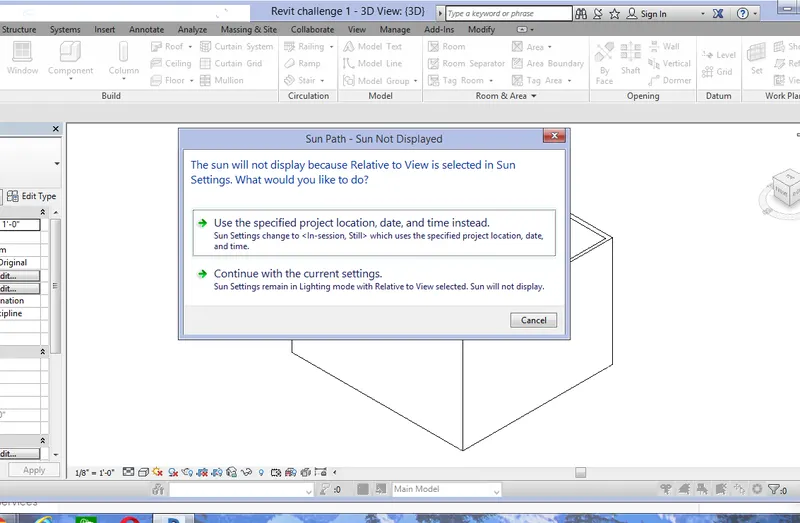
And the sun path is oned
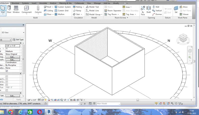
If we want to off the sunpath click on turn off sunpath and the sunpath will dissappears
And there is one option called sunsettings, there we can change the solar study, single day or multi day and we can also change location also using the map and time and after making changes click ok
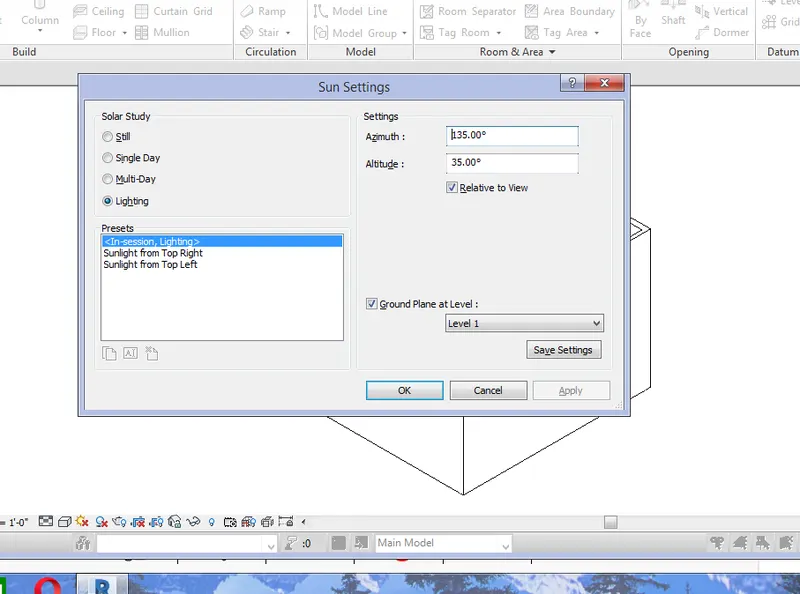
And then turn on the sunpath and we can find the sun over there
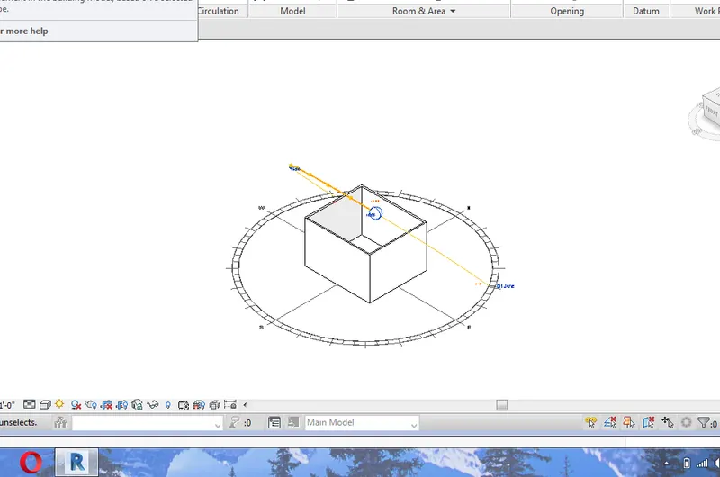
10) Aim: To change the project informations like project name, project issue date using manage tool bar
If we want to change the project informations click on manage tool bar
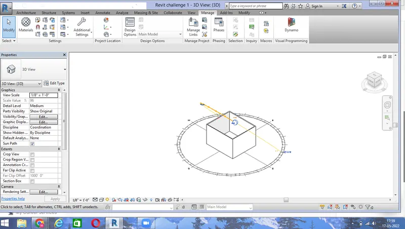
Then we have a icon called project information
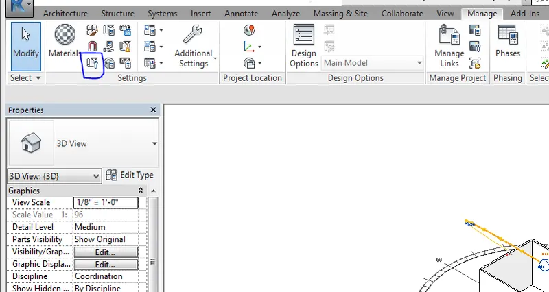
Click on the project information and the dialogue box opens and edit the contents which are there in that dialogue box
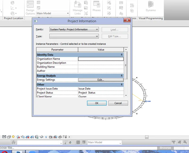
Give the organization name whichever we want
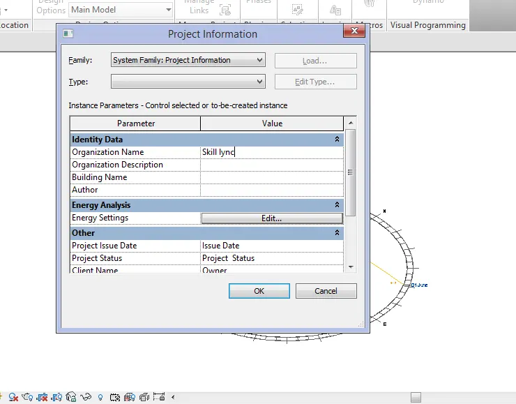
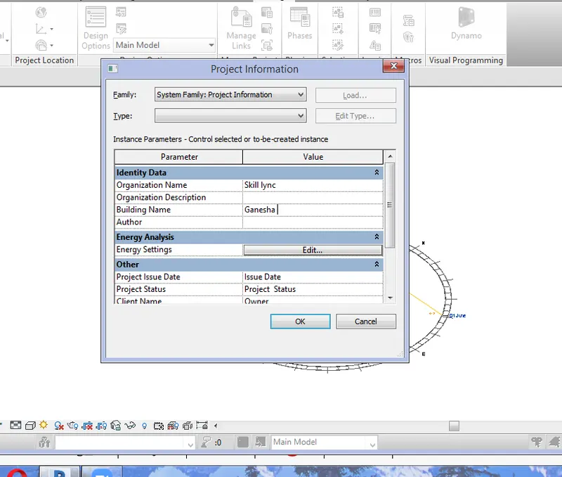
Give the buidling name whichever we want and we can also edit the organization description
And edit the project issue date in this dialogue box
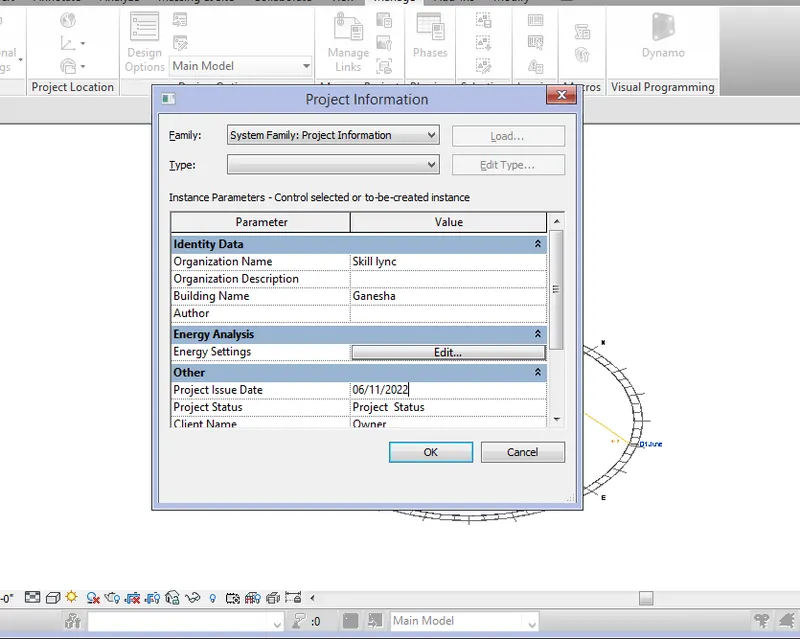
And also we can edit the project status
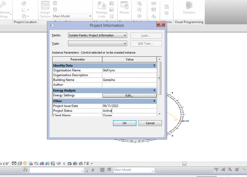
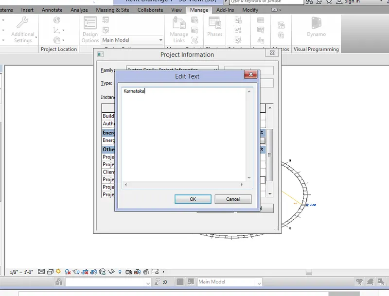
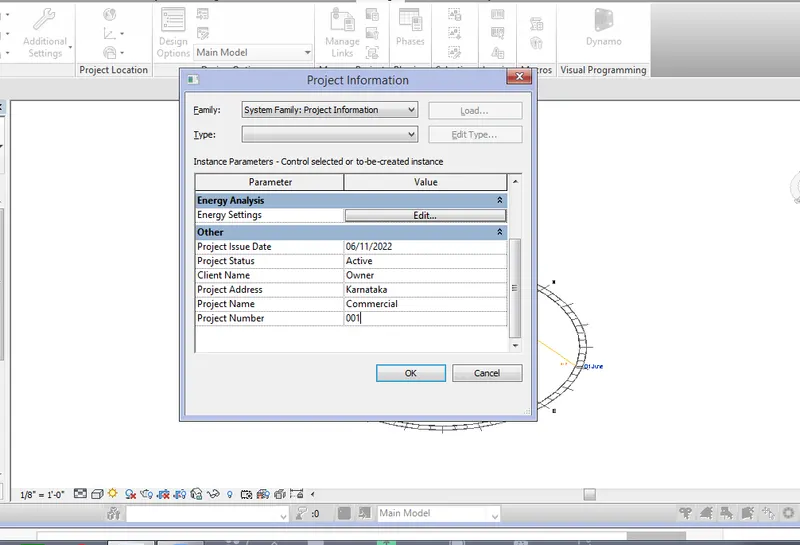
We can give owner name and project adress for project adress click on the three dots and we can give the adress there
We can also give project name as well as project number
13) The importance of coloborate tab in revit are
Work together
Cloud sharing
Work sharing
Central model
Understanding the importance of real-time coordination between MEP engineers, architects and construction managers means taking advantage of software tools that exist on the market today. Luckily Revit has been designed with collaboration in mind, by including powerful and efficient tools that make communication between disciplines understandable and easy.
For work together multiple revit models can be linked together allowing to work in contacts
When there is a need for coloboration to occur among users who are not in the same geographical locations, by using revit software, they can use multiple people can work together in a single project without any disturbance
Then work sharing, by enbling work sharing involves a creating a master project model known as central model from existing model. The central model stores the current model current ownership information for all workspace and elements in the project and act as the distribution point for all the changes made to the model. So all the users should have their own copy of the central model, they can edit locally in this workspace and they can also synchronize with central to publish changes the central model so that other users can see their works. Revit is really very useful for MEP engineers also who need to coloborate with other disciplines and also it supports the modeling. So coloboration tool keeps all the parties updated with the current project via, work sharing by revit cloud service it allows the key design features to the communicated effectively via, visual templates and colorfills and also it allows the user to divide model into work sets which can be a model editable or non editable for a current users to avoid confusion and listen computing the load and finally it allows the users to define parameter as the design progresses to make model wide changes for quick and easy.
11) In the revit software there is a dedicated tab known as analyze. The analyze tool bar can be used to perform structural analysis of the building, it has various options to enable that the analysis process
The first one is boudary condition, Boundary condition option enables to define points, lines and area boudary conditions in a analytical model, then load option load option applies point, line and area load to a model. Each load geometry is a family containing instances and type parameters apply load by sketching or using post components then next is load cases load cases can acts and edits load cases for the analytical model then load combinations, it can acts and edits the load combination for the analytical model setting a load combination includes defining its name, formula, type, state and usage and these are the basic anlytical tool under the analyze tab
12) The links are available in insert tab
The links that revits supports to be linked to the model are
Link revit
Link IFC
Link CAD
a) Link revit links links another model to the current model, we can link models together, for example, to specify the relative locations of individual buildings on a campus, or to coordinate efforts across disciplines( architectural, structural and engineering)
b) Links IFC links an ifc file to the current project to reference its information for additional design work
if we later makes change to the original ifc file and reload the link, the project updates to reflect the IFC file changes
Before linking an IFC file, use open> IFC options to specify the project template to use and to load a file that maps IFC classes to revit categories
If we want to use the IFC data as a starting point for a new model( not as a reference information), then use open> IFC from the appication menu instead
c) Link CAD links a CAD file to the current revit project
Linking is similar to having an xref in Autocad, When the original linked file changes, these changes are reflected(if possible) in the file when we reload the project
In manage links provides options for managing links to the building models, CAD files, DWF markup files, and point clouds
From the manage links dialog, we can also link revit models and CAD files to the current projects