Introduction to REVIT concepts
Question 1) From the file menu, create a new project (Structural / Architectural / Construction template ) and name the project appropriately.
AIM: To create a new project (Structural/Architectural/Construction template) and name the project appropriately from the file menu using the Revit software 2023.
INTRODUCTION: Revit is a software which create virtual building with all its properties. Revit has a huge library for modelling in the software itself. It is like drawing a real building in this virtual workspace. It has huge tools to create virtual buildings. Revit allows architects,civil engineers and the person related to the designing field to design a building in the 3D format. in this question we are using the properties palette,file menu and the open option.
PROCEDURE:
- First of all open the REVIT 2023 software.
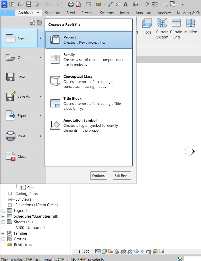
- To create a new project using the file menu, we have to click on the file option on the upper left side of workspace.
- After clicking the file option click on the NEW option then the other dialouge box pops up and from that dialouge box we need to click on the PROJECT option.
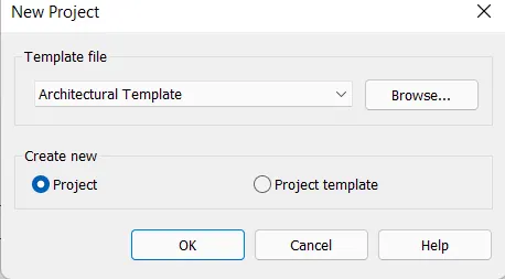
- After clicking the project option from that pop up then there is another dialouge box appears on the screen named NEW PROJECT.
- From there only we have the option template file from there we have to change the Template file name.
- Under the option Create new select the option PROJECT and then click on the OK button.
- And now the new project is created.
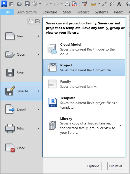
- Now go to the file option click on the save as option and from there only name the project as CHALLENGE-1.
- Now click on the option OK.
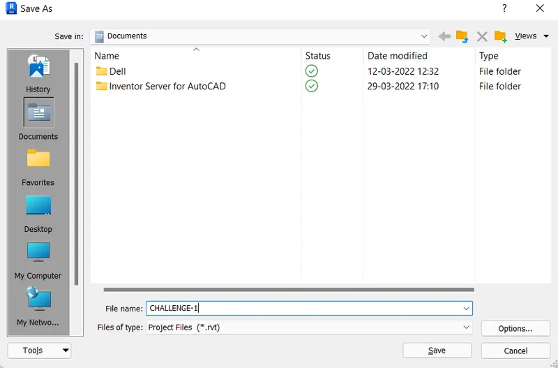
- So the file name is changed to CHALLENGE-1.
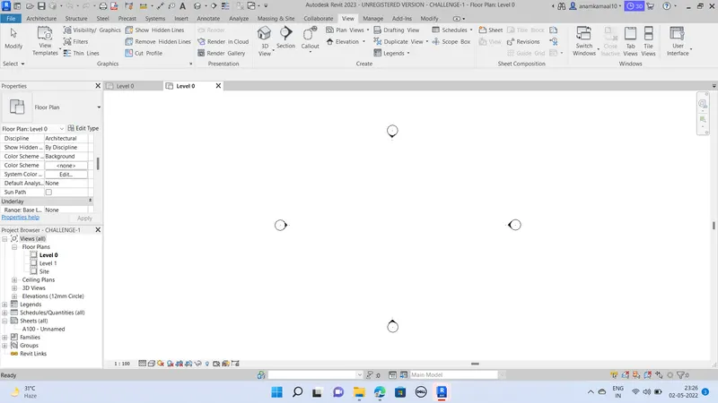
- These steps are same for the Structural/Architectural/Construction template. Repeat this same steps to create the new file and change the name of the project.
Question 2) Save the new project file. Close and open using icons from file toolbar.
AIM: To close and open the new project file using file toolbar.
INTRODUCTION: This open option in the revit allows us to open new or existing file within the software. And the close option allows us to close the revit software. And we can save the files using the save as option in the file toolbaar.
PROCEDURE:
- After saving the new created file as CHALLENGE-1 in the above steps.
- Now click on the file toolbar.
- Click on the CLOSE option to close the file.
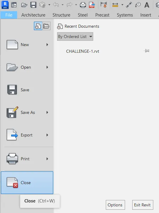
- And now to open the file from the file toolbar.
- Just click on the OPEN option.
- After that click on the PROJECT option .
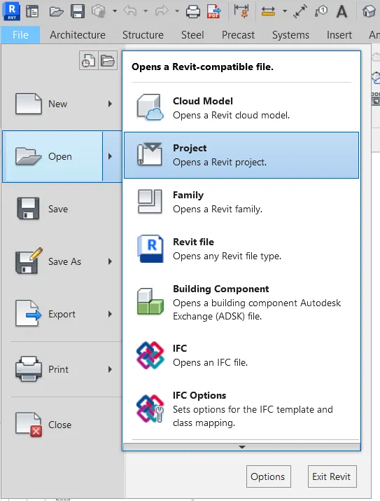
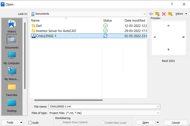
- After clicking on the PROJECT option the another window opens. From there open the recently saved file.
- And then press OPEN.
- The file is open.
Question 3) From the architecture/ structure toolbar familiarize with options to draw a wall. Create a rectangular layout of walls of about 40’-0” X 35’-0”
AIM: To Create a rectangular layout of walls of about 40'-0" X 35'-0" from the architectural or structural toolbaar.
INTRODUCTION: In the architecture toolbar there are different types of wall of different sizes and of different types. We can select the different walls for the different projects using the architecture toolbars and properties section.
PROCEDURE:
- Just click on the open option and open the previously created file named CHALLENGE-1.
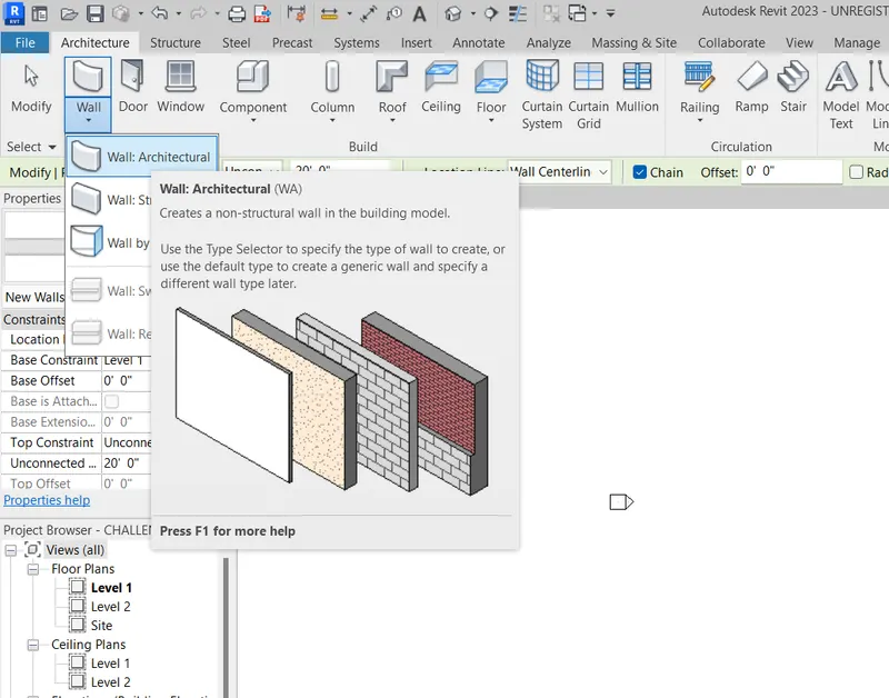
- Select the wall tool from the Architecture option click on the architecture menu.
- Then just click on the wall option.
- From that option click on the WALL:ARCHITECTURAL option.
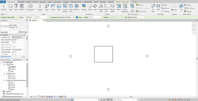
- Now specify the location point and give the direction, just move the cursor in the right side of the screen and type 40' in the box and then press Enter.
- Now move the cursor in the downward direction and type 35' and then press enter.
- Again move the cursor in the left direction and then type 40' and press Enter.
- Now move the cursor in the upward direction and then type 35' and then press Enter.
- A rectangular layout of the wall of 40'-0" X 35'-0" is created.
Question 4) From the Annotate toolbar use the aligned option to add dimensions to the layout.
AIM: To add the dimensions to the layout from the annotate toolbaar using the aligned option.
INTRODUCTION: Annotate toolbar different options is used to give the dimensions to the objects.
PROCEDURE:
- Just click on the open option and open the previously created file named CHALLENGE-1.
- Now go to the ANNOTATE toolbar and from there click on the aligned option.
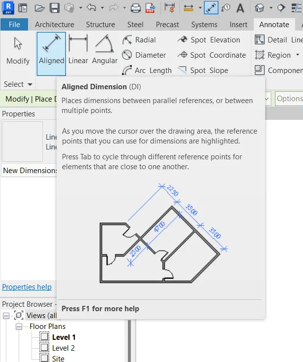
- After selecting the aligned option. Specify the location of the dimension line.
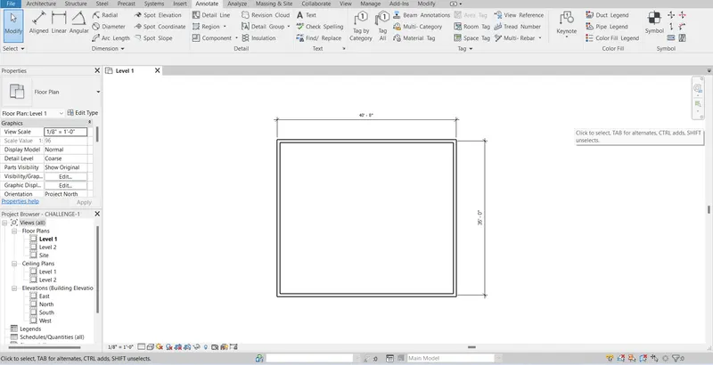
- And then take the dimension on the either sides of the layout as shown in the below figure.
Question 5) Use the properties browser to switch to different wall types.
AIM: To switch the different wall types using the properties browser.
INTRODUCTION: In the properties browser we can change the wall type. In this properties browser there are different wall sizes available.
PROCEDURE:
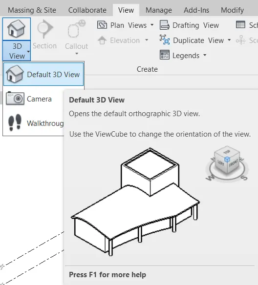
- First of all click on the 3D view option and then click on on the 3D view option in order to see the 3D object of the rectangular block.
- So from that rectangular layout we select the one wall in order to change the different wall types as shown in the below figure.
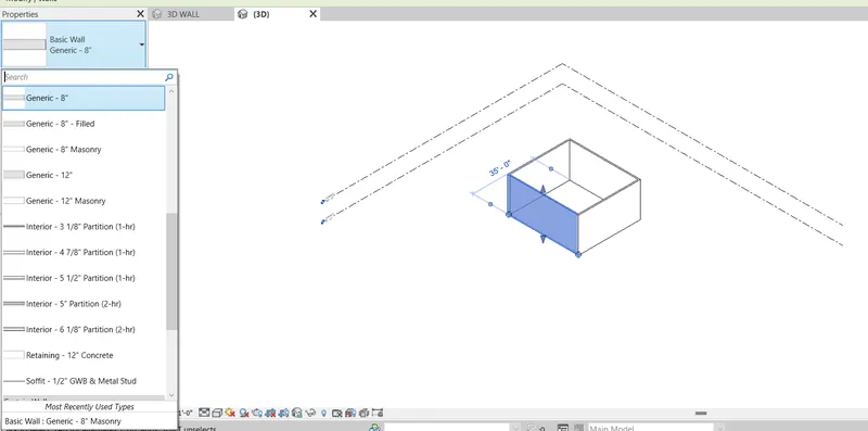
- From this property browser the walls are then switched to the different wall types and sizes.
- After opening the file just go to the property browser on the left hand side of the drawing area.
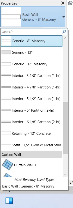
- Now click on the option which you wish to change in the created wall.
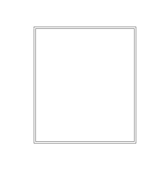
- Here i want Generic-8" Masonary wall, so i clicked on that option and then draw the rectangular layout with the size of 40'-0" X 35'-0'. as shown in the below figure.
Question 6) Create a 3D view from the view toolbar and save the view with the appropriate name.
AIM: To create a 3d view from the view tool baar and save the same with the appropriate name.
INTRODUCTION: In the 3D view we can see the 3D views from the different angles and different positions.
PROCEDURE:
- First of all click on the open option and open the previously created file named CHALLENGE-1.
- Now after opening the file go to the view tab.
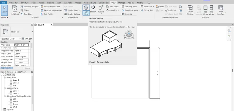
- From the vie tab select the option 3D VIEW and after clicking on the 3d view another dialouge box pops up so from there click on the DEFAULT 3D VIEW.
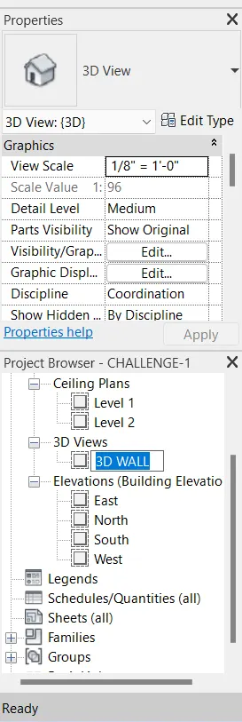
- After this go to the project browser option from there only click on the 3D views.
- Now select the 3D view option and then right click.
- After that we are able to remane the 3D view option.
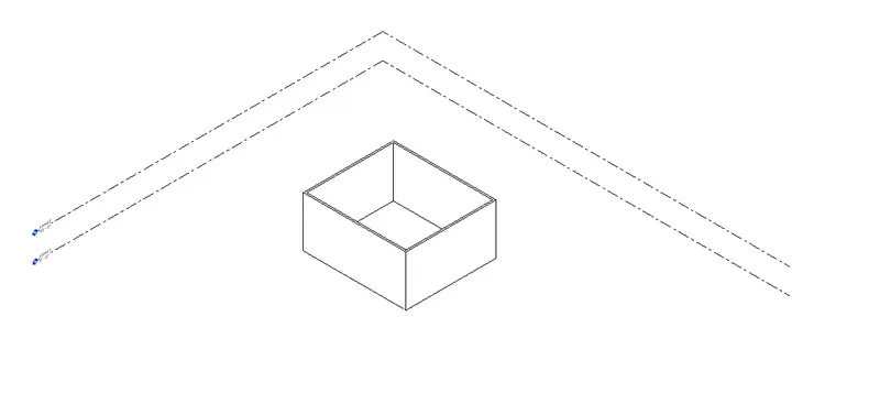
- Below is the final result of creating 3D view.
Question 7) Navigate through the 3D model using the view cube. Orbit/pan through the model layout created.
AIM: Using the view cube navigate through the 3D model using the view cube and orbit/pan the model layout created.
INTRODUCTION: It allows to navigate the model using the orbit,pan options.
PROCEDURE:
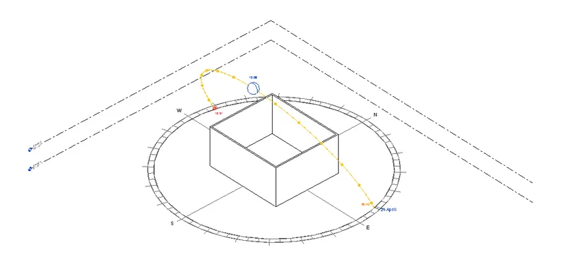
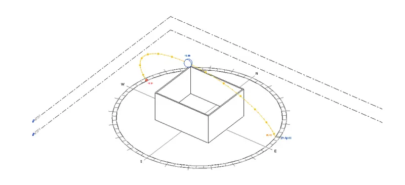
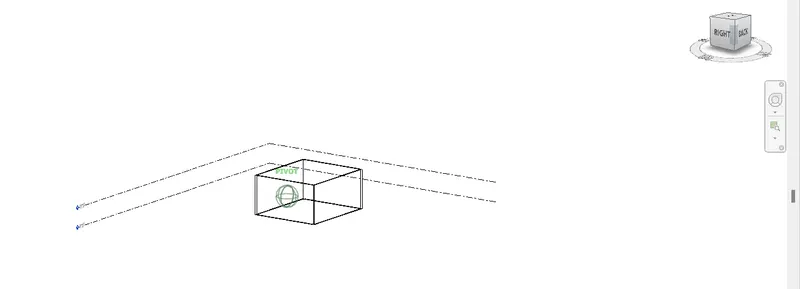
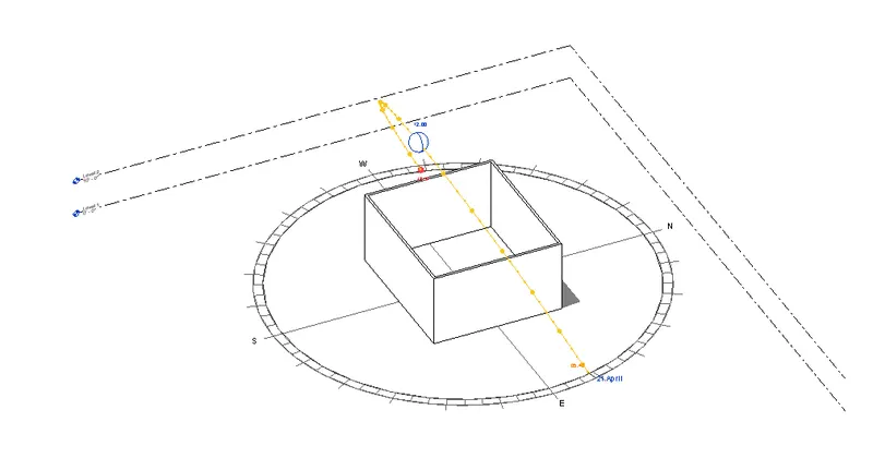
- First of all move the cursor to the view cube and press the left click on the view cube and hold the view cube with the cursor and rotate the view in the different directions in which direction we want to rotate.
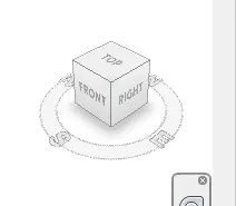
- This is the picture of the view cube.
- Now with the help of this view cube we can rotate the 3D model in different directions as shown in the below figures:
Now using the pan/orbit:
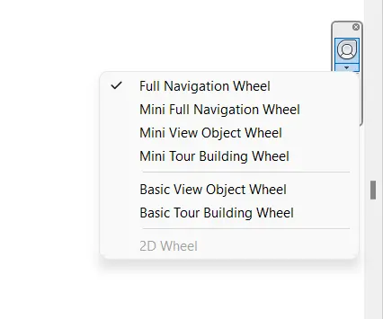
- We can find the steering wheel on the right side of the screen.
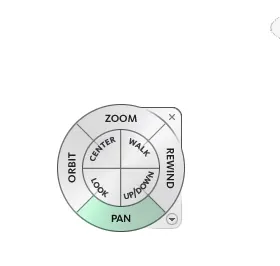
- After doing this we have to select the pan option fron this steering wheel. It is on the bottom of the steering wheel.
- Click on the Pan option, then hold and move the 3D model to view the different position as shown in the below figure:
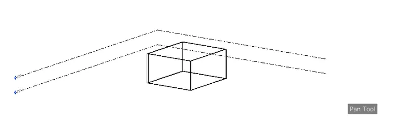
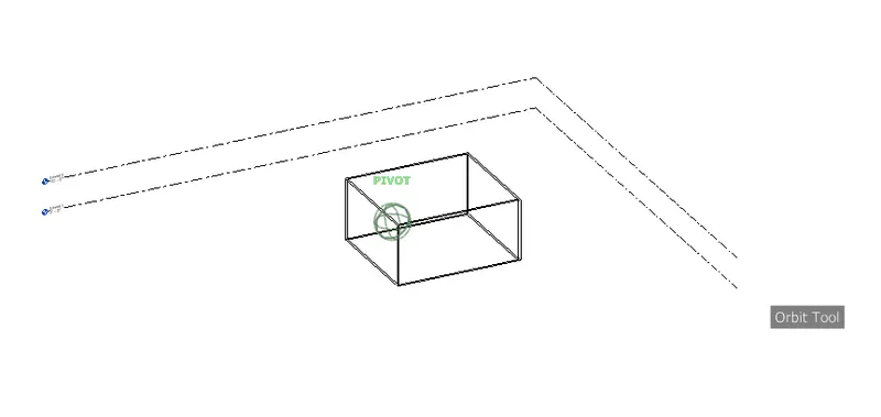
- Now repeat the same procedure as we had done for the pan option. And this time click on the orbit option.
- From here we can find the streering wheel on the right side of the screen.
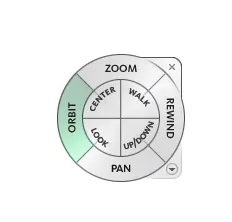
- After doing this we have to select the orbit option from this steering wheel. It is on the left side of the steering wheel.
- Click on the Orbit option, then hold and move the 3D model to view the different position as shown in the below figure:
Question 8) Use the visibility settings option below to switch model to shaded, realistic, hidden lines options.
AIM: To switch the model to shaded,realistic,hidden lines option using the visibility setting options.
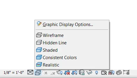
INTRODUCTION: Visibility settings allow as to cange the visibility of the models such as:
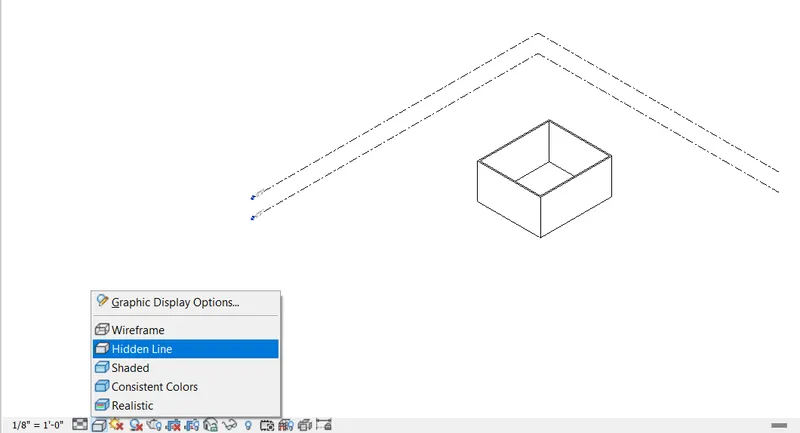
- Wireframe.
- Hiddenlines.
- Shaded.
- Consistent colours.
- Realistic.
PROCEDURE:
- We can find the visibility setting option at the bottom of the screen from there we can change the visuality of the models.
- To change the visuality of the models we have to click on the cube like sign on the bottom its a visual setting sign. After clicking on it a box pops-ups and in that box there are few visual setting options.
- Now Click on the bottom on the graphic display setting option then from there select the Realistic option and then Enter.
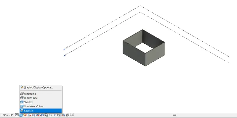
- This will change the visual setting of the object to to Realistic.
- To change the visuality of the models we have to click on the cube like sign on the bottom its a visual setting sign. After clicking on it a box pops-ups and in that box there are few visual setting options.
- Now Click on the bottom on the graphic display setting option then from there select the shaded option and then Enter.
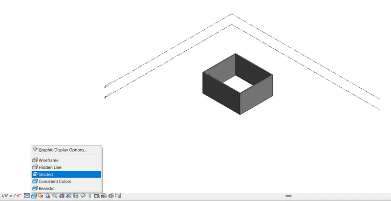
- This will change the visual setting of the object to Shaded.
- To change the visuality of the models we have to click on the cube like sign on the bottom its a visual setting sign. After clicking on it a box pops-ups and in that box there are few visual setting options.
- Now Click on the bottom on the graphic display setting option then from there select the hidden lines option and then Enter.
Question 9) Turn the sun path on and off to view shadings in the layout created.
Aim: To turn the sun path on and off to view shadings in the layout created.
INTRODUCTION: To learn the impact of the sun position on your building we use the sun and shadow settings in the Revit to visualize the position of the sun at any time or day.
PROCEDURE:
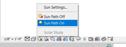
- First of all click on the sun path icon which is at the bottom of the screen.
- And select the sun path ON option.
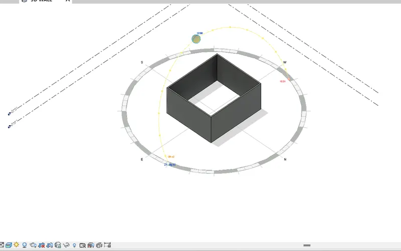
- After clicking on the sun path ON option then it displays the compass, the position of the sun and the time and date of the year on the screen.
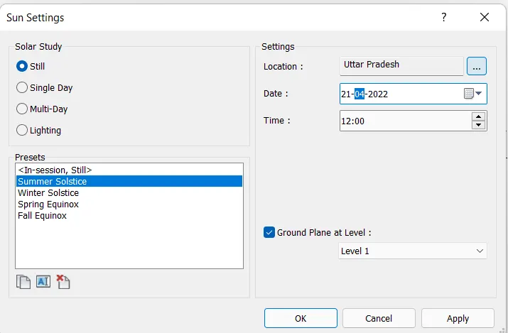
- We can also change the sun settings by clicking on the option Sun Setting.
Question 10) Use the Manage toolbar to enter project settings, project name, and project issue date (choose according to your convenience).
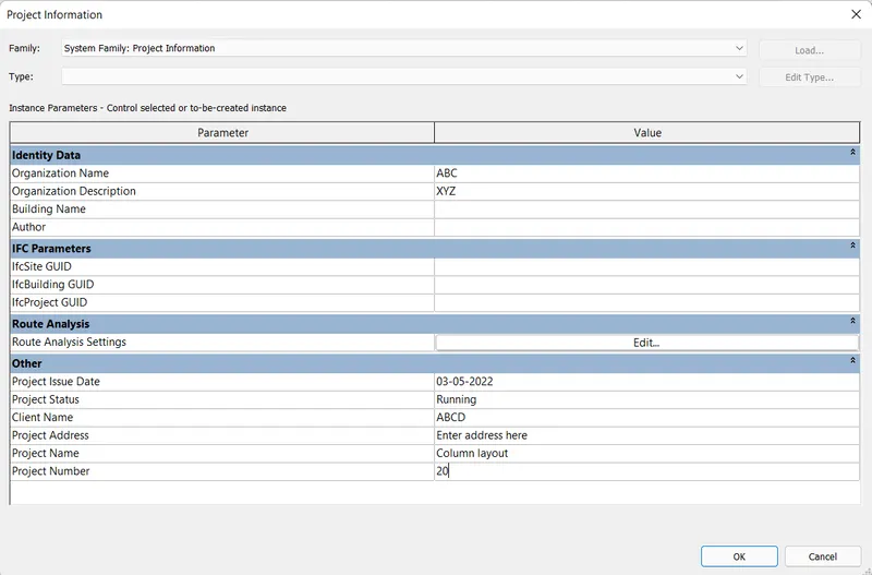
AIM: To use the manage toolbar to enter the project settings,project name and the issue date.
INTRODUCTION: In manage toolbar we can manege various things. like material,snaps,object styles,project information,shared information,ptrojects units,location,coordinates etc.
In this toolbar we need to select the manage toolbaar and give the details of the project.
PROCEDURE:
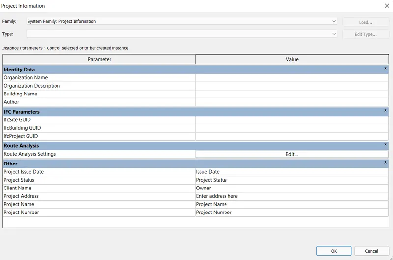
- Firstly click on the manage toolbar, we need to select the project information and enter the project details.

- After selecting the project information, a new window opens as shown in the below figure:
- Now we have to fill the required details related to the project in the project in formation window as shown in the below figure:
Question 11) What is the Analyze toolbar used in Revit? How it is beneficial for design and modeling.
Answer: Analyze tool bar : Analyze tool bar is used to perform the analysis on our structures.

- Its boundary conditions helps us to define the point,line and area boundary conditions in our drawing.
- We can also apply point load to our drawing to analyze the performance.
- Load: Using this option we can apply or we can say that we can add the different loads to the building to analyze the design standards.
- Load cases: Using the load cases options we can add the loads on the building or we can say that we can edit the loads on our projects.
- Load combinations: Using this option of load combination we can combine different load cases using this option.
- In analytical model tools option we can adjust the model, reset the model and can perform the checks on the model.
- In the reports and schedule options we can prepare the heating and cooling load reports, panel schedules ,duct pressure report etc.
Question 12) What are the links that Revit supports to be linked to the model?
Answer: Open an existing model. Click on the insert tab link pannel and after clicking on the insert tab we can find the links that revit supports to be linked to the model and they are:
- Link Revit.
- Link IFC.
- Link CAD.
- Manage links.

- Link Revit: Using this option we can link the other models like architectural or structural or mechanical model. We can link the other Revit models to the current revit models.
- LInk IFCS: To links IFC file to the current model to reference its information for additional design work.
- Link CAD: In this option Revit allows us to link any 2D cad file to the revit file to make the 3D by using the revit tools.
- Manage links: From using this link we can also link revit models and CAD files to the current drawing. It provides the feature to manage the links to the building models.
Question 13) Why do you need the Collaborate tab in Revit? How it supports modeling and its efficiency.
Answer: We need collaborate tab in revit because it provide to collaborate with the other team menbers who are also using the Revit software.
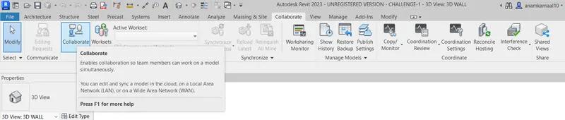
- Using this collaboration tab in revit we can link multiple Revit models all together, allowing other team members to work together.
- Using the LAN network, peoples can work together in the same revit model.
- If the collaboration needs among the different geographical location i.e those who are not in the same LAN network Revit allows to work together even with the different geographical location by using the Revit server or Revit cloud worksharing optin.