Independent Research Project
REPORT
TRANSIENT STRUCTURAL ANALYSIS ON FOUR CYLINDER ENGINE
AIM
To perform transient structural analysis on four cylinder engine and to find equivalent stress, strain and deformation developed in the engine while the engine is operating in real life condition.
FOUR CYLINDER ENGINE
A 4-cylinder engine is a common type of internal combustion engine used in cars, motorcycle and trucks. It has four cylinders, all are aligned in a row. Each cylinder contains a piston, which moves up and down, converting the burning fuel into mechanical power.
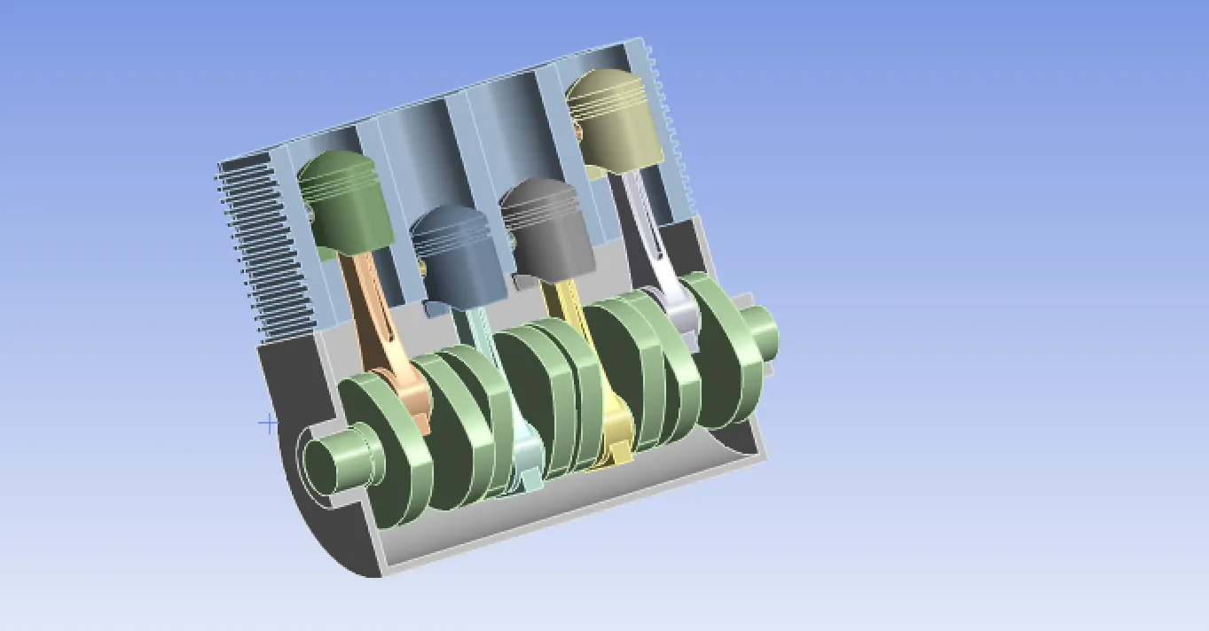
MOTIVATION FOR THIS PROJECT
The four cylinder engine plays a critical role in the automotive industry and serves as a practical and reliable engine type. This makes it a valuable focus area for the project.
Transient structural analysis plays a crucial role in design, optimization and reliability assessment of an engine.
PROCEDURE
Choose transient structural in Ansys. Import the model in Ansys work bench and supress the crank case.
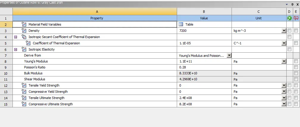
First we need to choose materials for each parts of the engine. For cylinder block, Gray cast iron is used,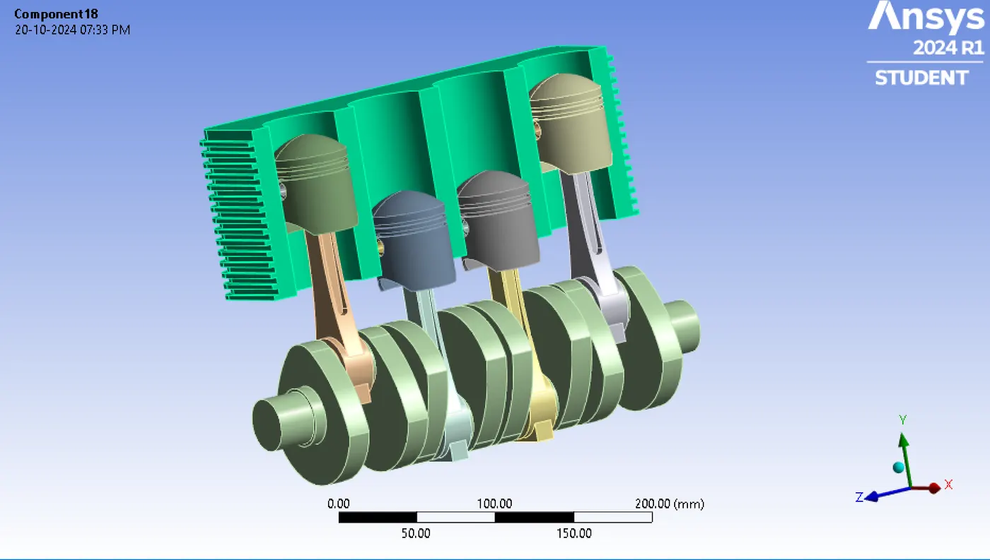
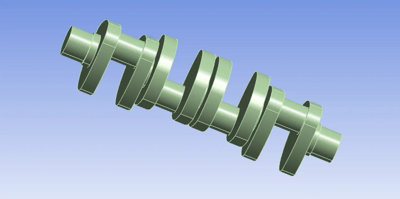
For crank shaft, forged steel is used.
 Forged steel is created using the properties shown below,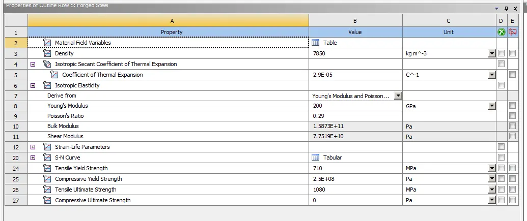
The crank shaft is essentially the backbone of the internal combustion engine. It converts linear motion into a rotational motion. Forged steel have high strength and fatigue resistance.
For connecting rod, forged steel is also used.
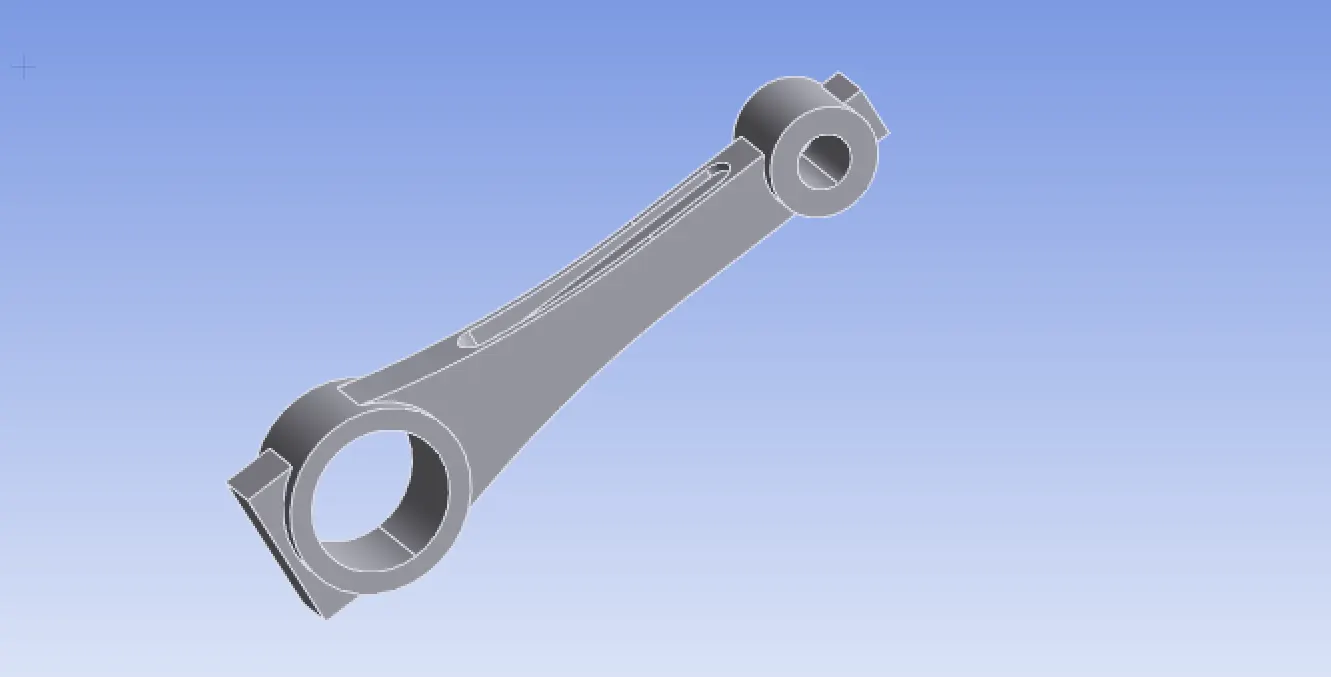
Connecting rod transfers up and down motion of the piston to the crank shaft.
PISTON
The main function of the piston is to convert the energy formed during combustion into mechanical work. Pistons are always moving up and down.
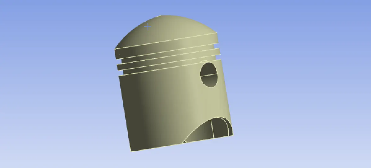 Aluminium alloy is used for piston and the properties are below,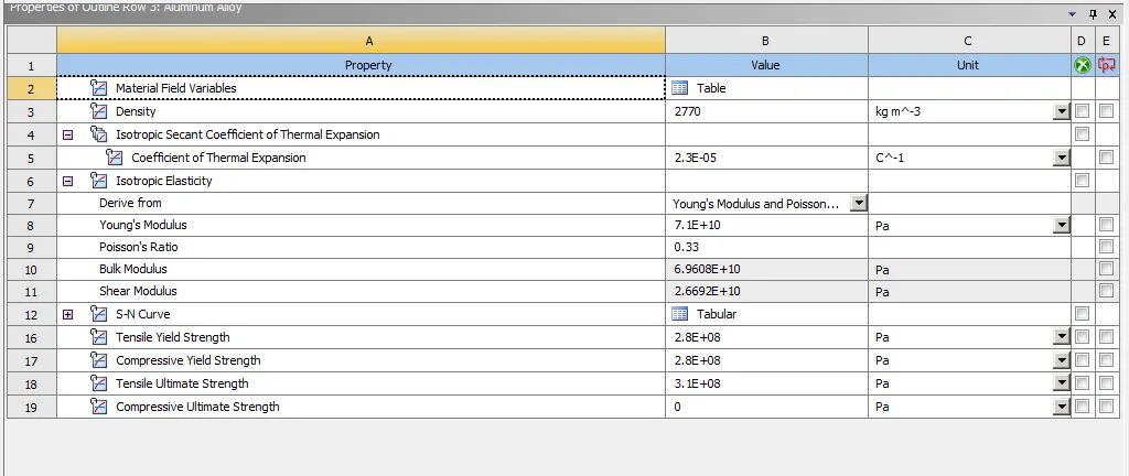
PISTON PIN
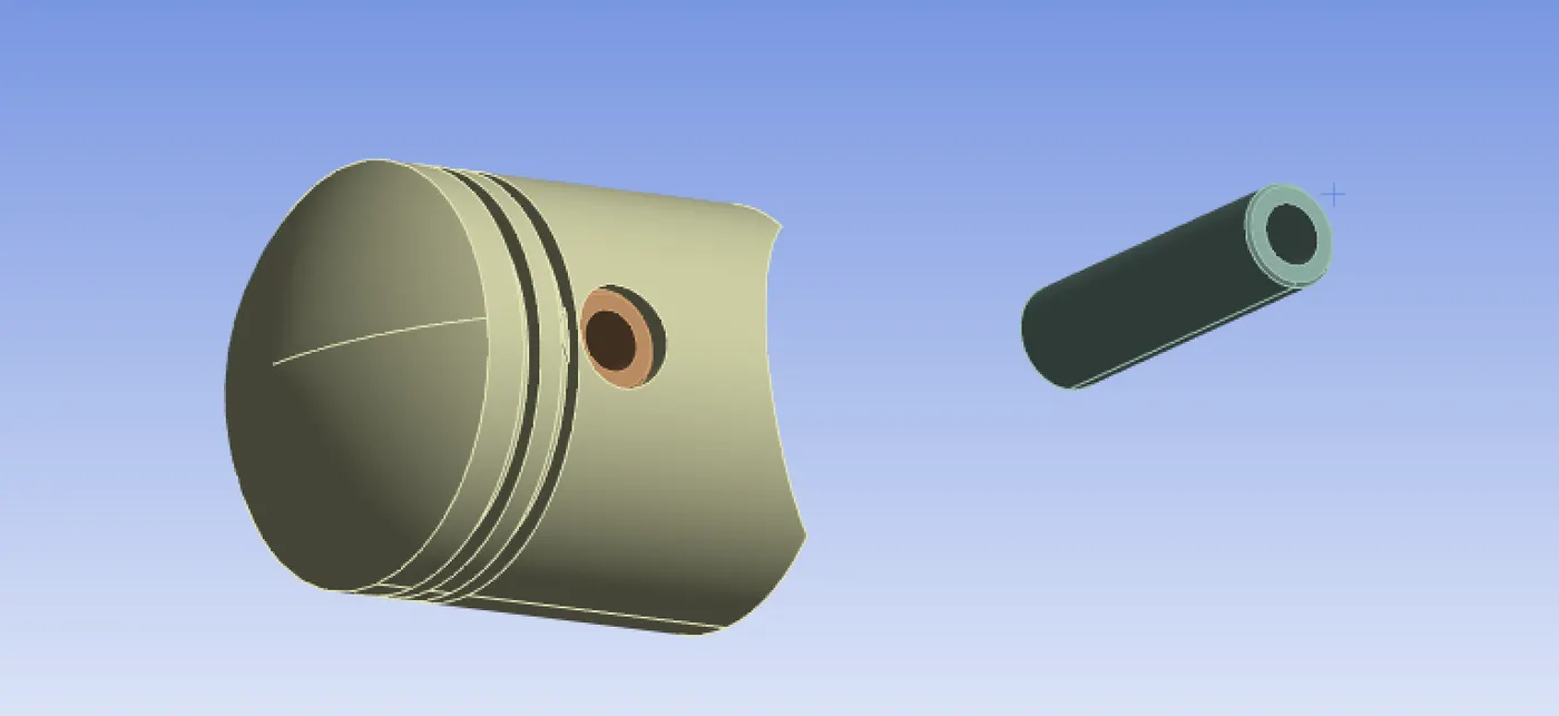 It connects the piston to the connecting rod and provides a pivot point between the connecting rod and the piston. Piston pins are made hollow to reduce inertia load due to reciprocating motion.
Here I am using titanium alloy for the piston pins,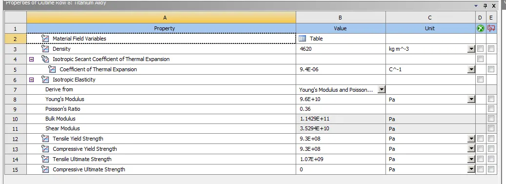
There is only one half of cylinder block, so the other half can be included using symmetry option.
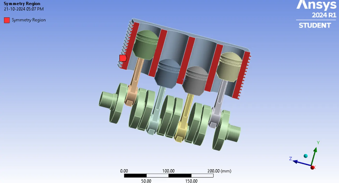
For contacts, the contacts between piston and cylinder is applied and given a frictional coefficient of 0.05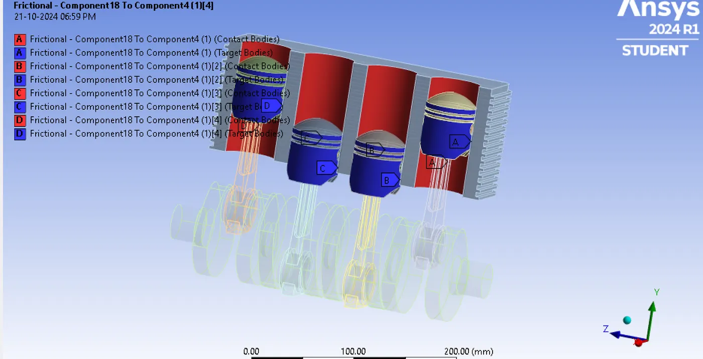
JOINTS
Body to ground-Revolute joint is applied to the crank shaft.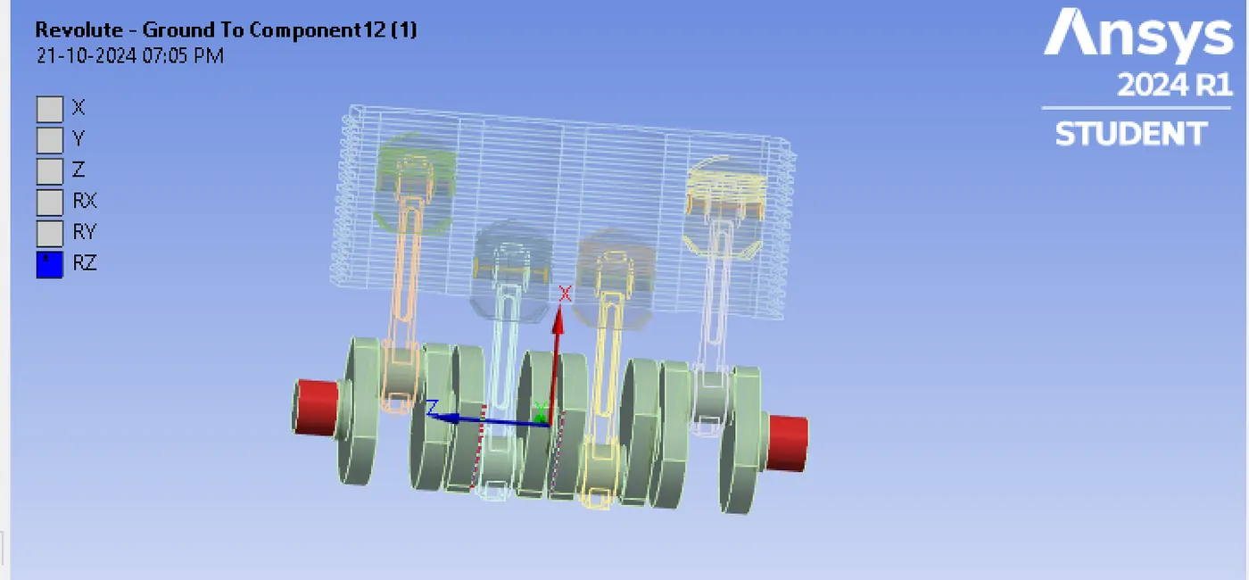
Body to body-Revolute joint is applied between crank shaft and connecting rod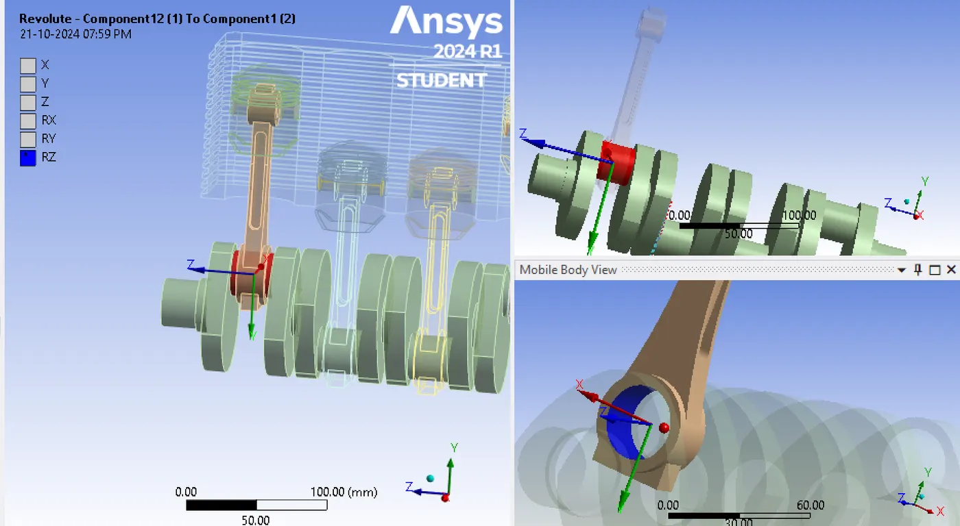
It is applied for all four connection between crank shaft and connecting rod.
Body to body-Revolute joint is applied between connecting rod and piston pin.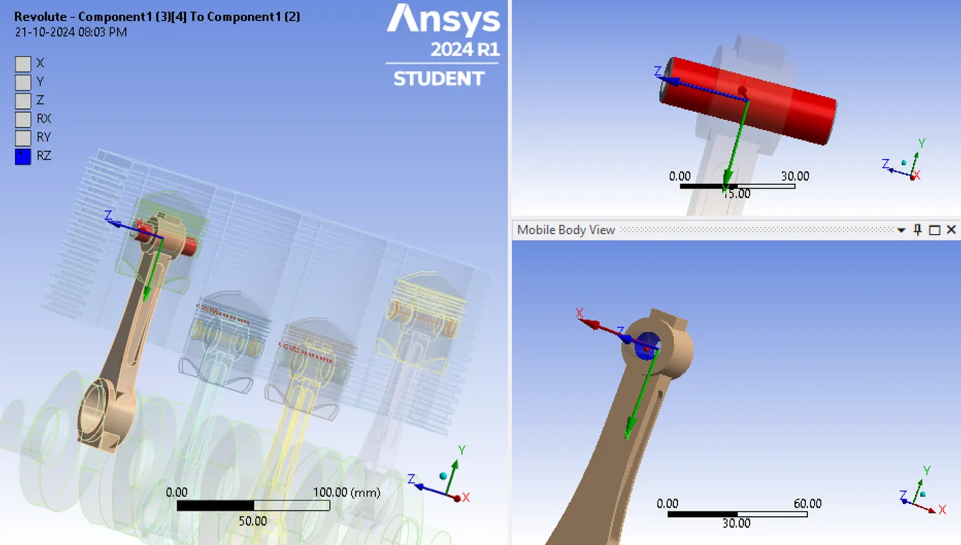
It is applied for all 4 connection between piston pin and crank shaft.
Body to body-Fixed joint is applied between piston and piston pin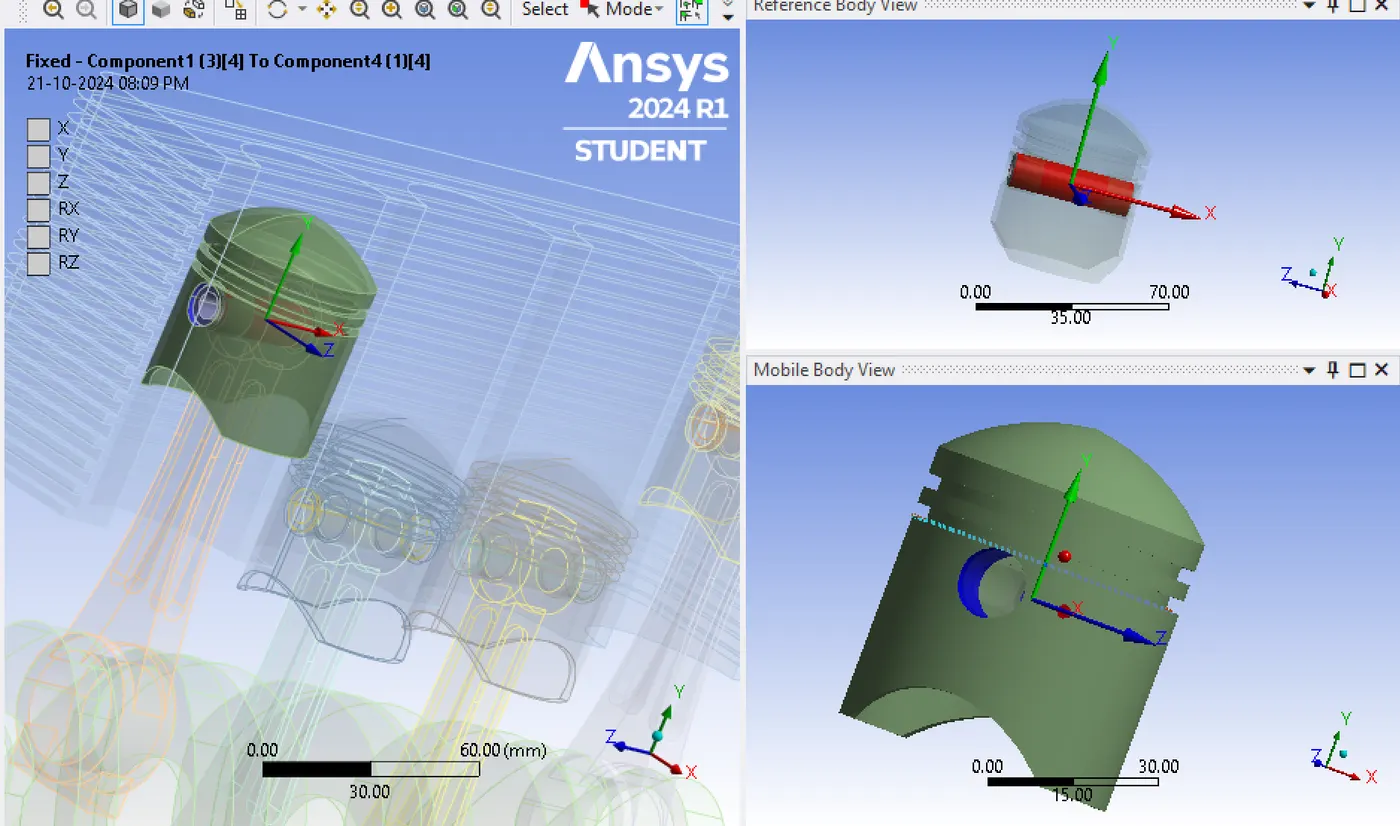 and it is applied to all four connections.
Body to ground-Translational joint is applied to the cylinder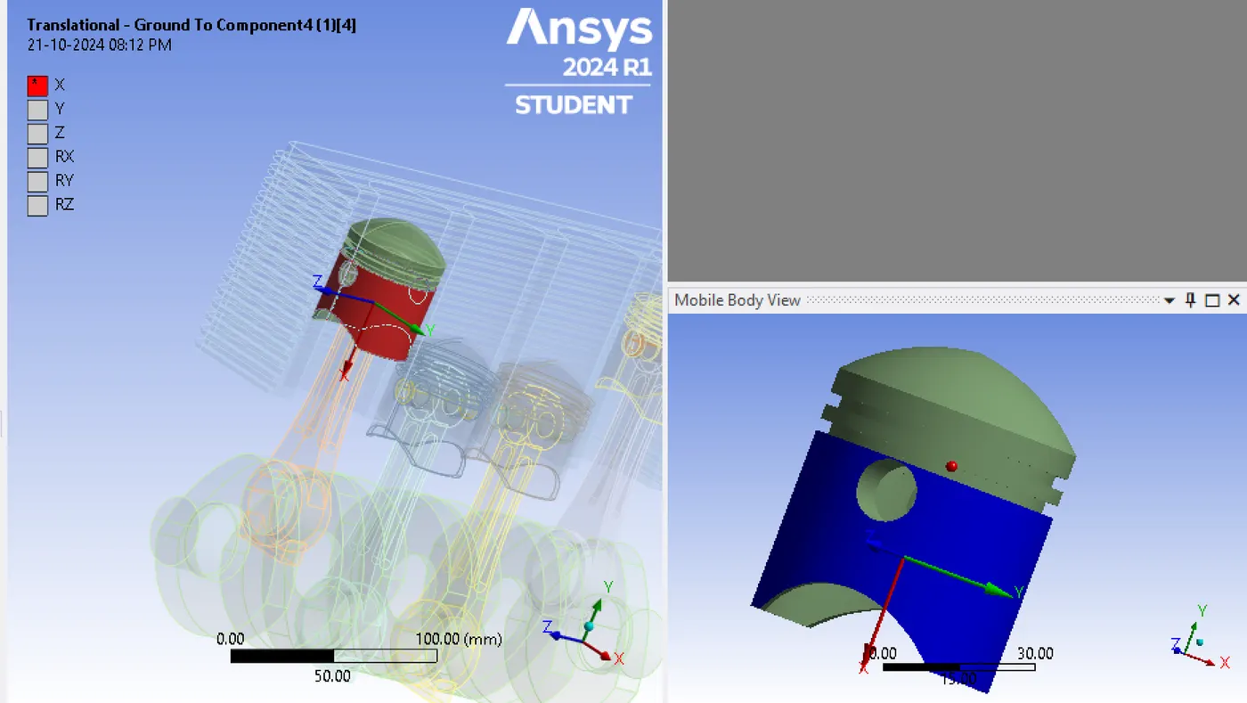 for all four cylinders, to have up and down motion the translational joints are applied.
MESH
For the contacts between piston and cylinder, a face sizing of 6mm is applied 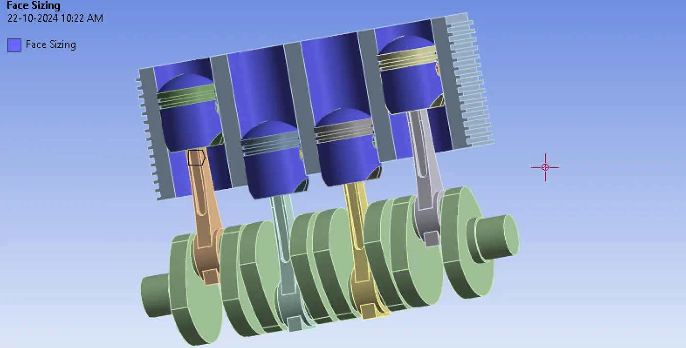 and for the other parts, a 10mm mesh is provided.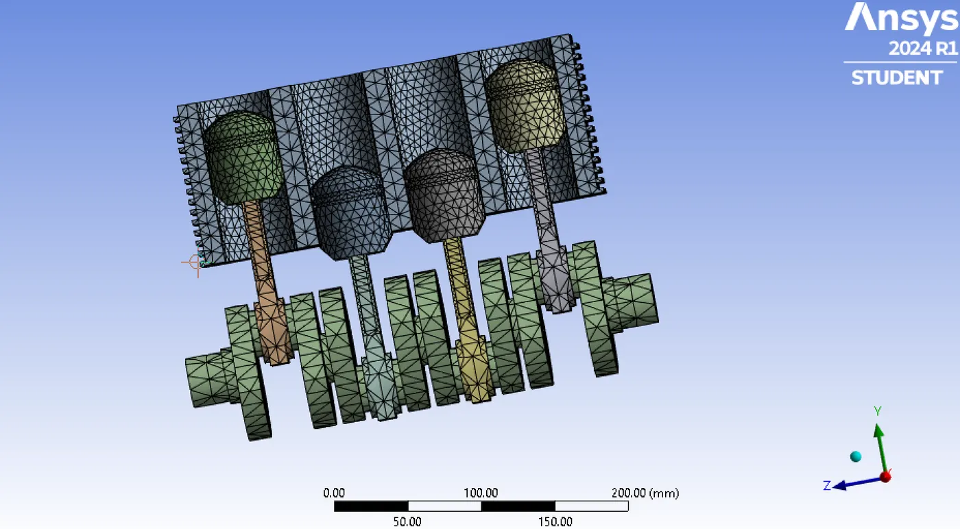
ANALYSIS SETTING
This analysis is running through 6 steps and the details for the analysis setting including time steps are below,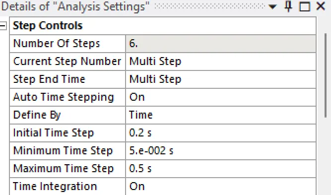
LOADING CONDITIONS
Fixed support is provided for the cylinder block.
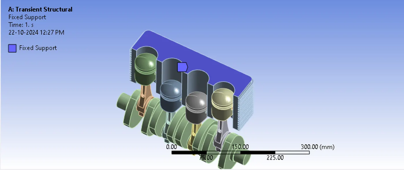
The power generation in internal combustion engine consist of four strokes,
1. The Intake stroke
2. The Compression stroke
3. The Power stroke
4. The Exhaust stroke
The useful mechanical power is generated in the power stroke. Here the combustion of air-fuel mixture takes place. The combustion generates high pressure gases and the gases expand rapidly forcing the piston down with great force.
Here I am giving a constant pressure of 6 MPa for all steps.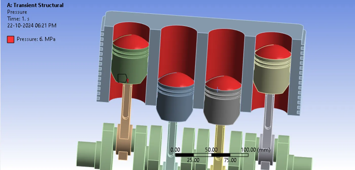
High temperature will be developed during the combustion process, so I gave constant thermal conditions to the cylinder and the pistons.
Temperature of 250 Degree Celsius is given to pistons.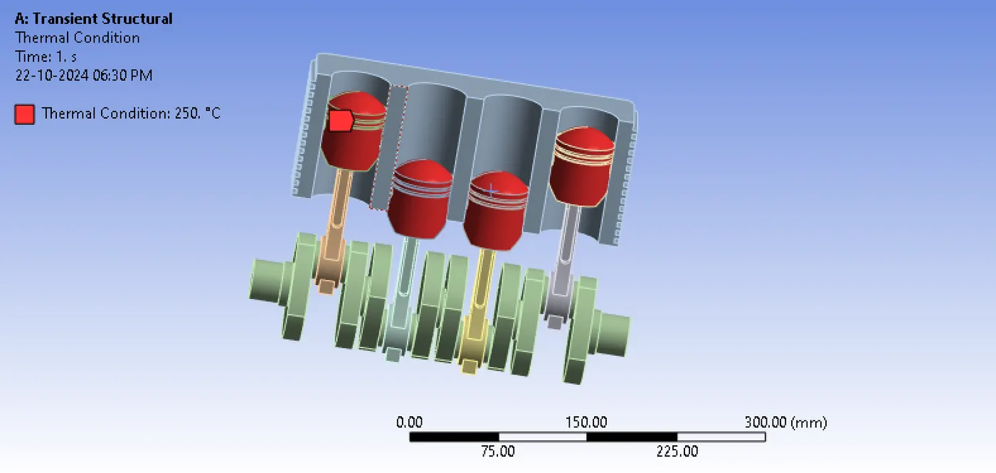
Temperature of 150 Degree Celsius is given to cylinder block.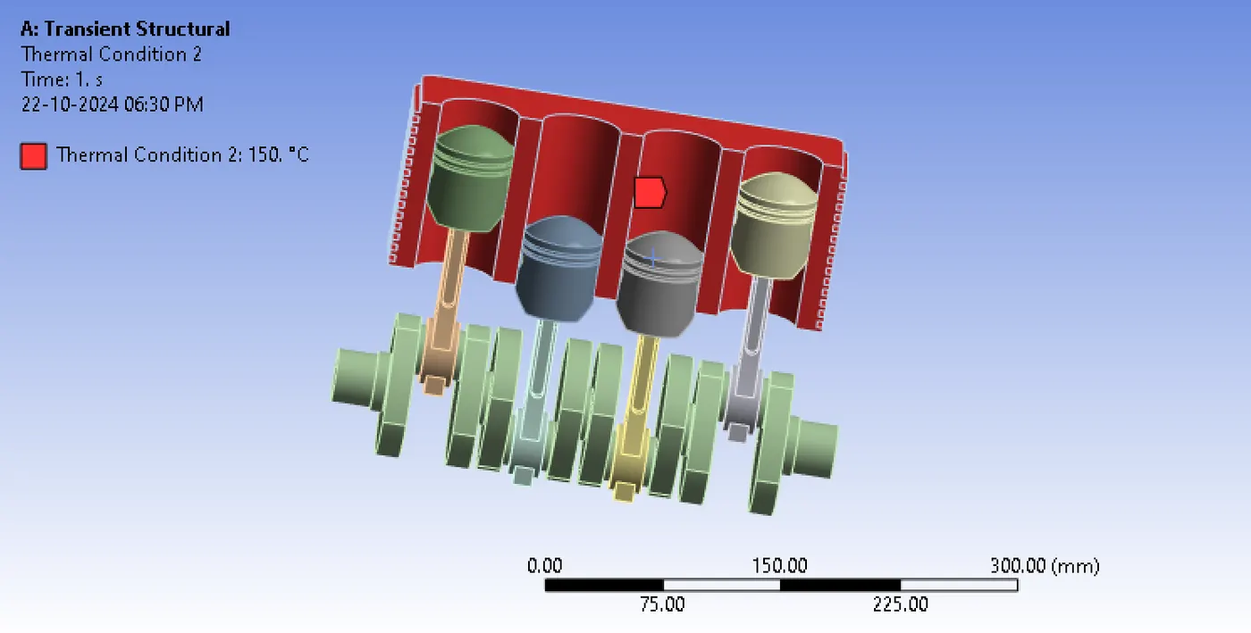
The crank shaft is rotated to 720 degrees through six steps.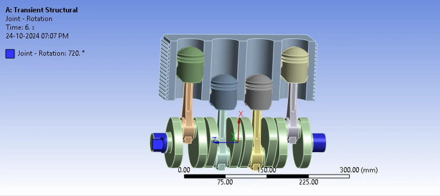
Now it is all set to run the simulation, the aim to analyse the deformation, stress and strain developing in this engine while working.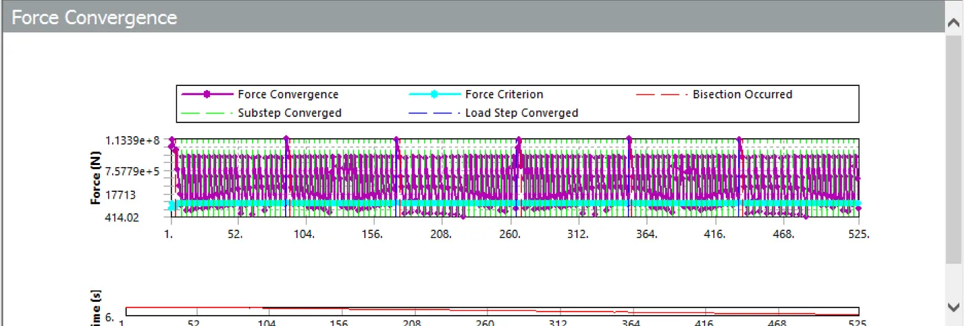
The above diagram is showing that the solution has converged.
RESULTS
THE EQUIVALENT STRESS
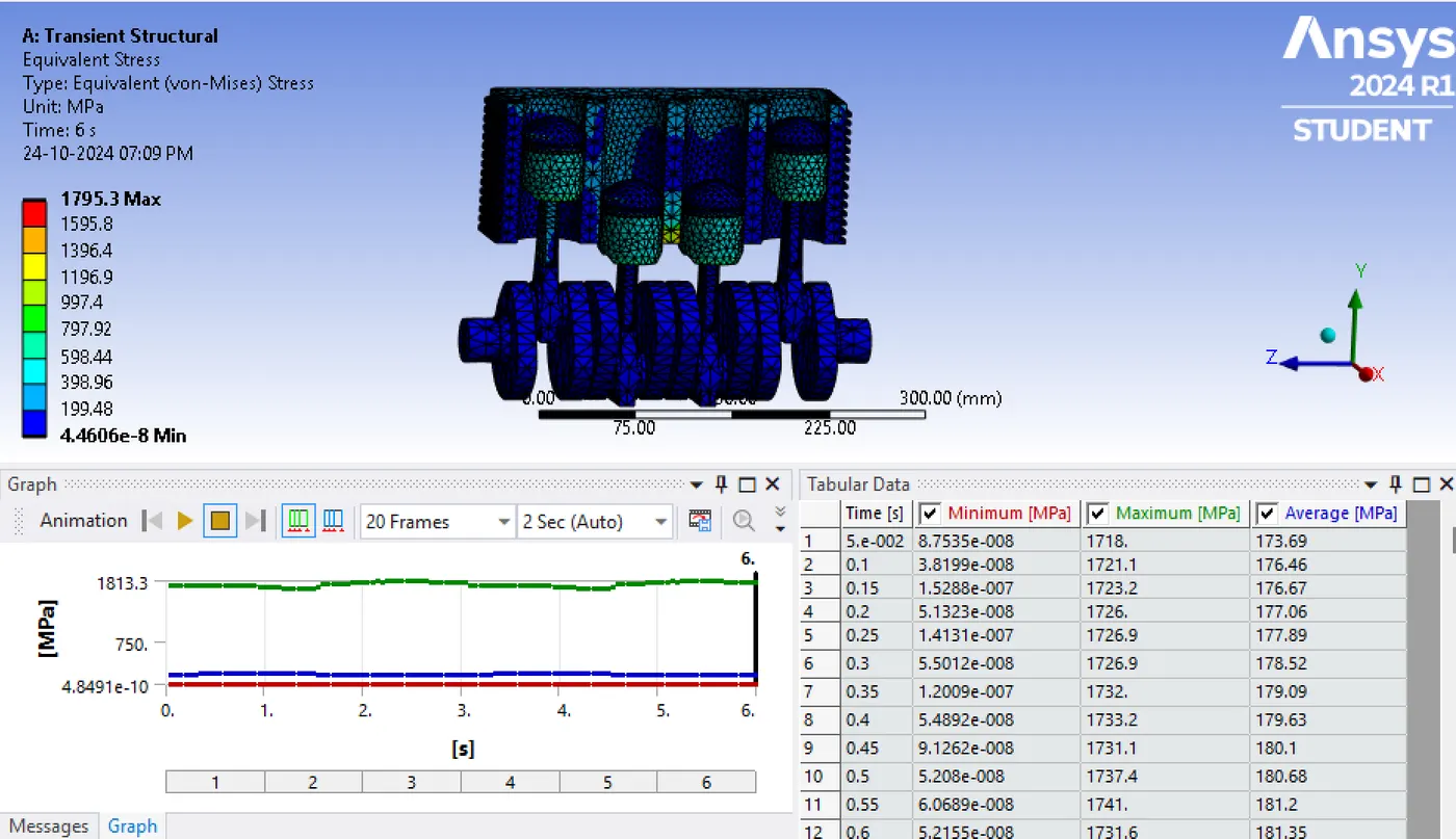
THE EQUIVALENT ELASTIC STRAIN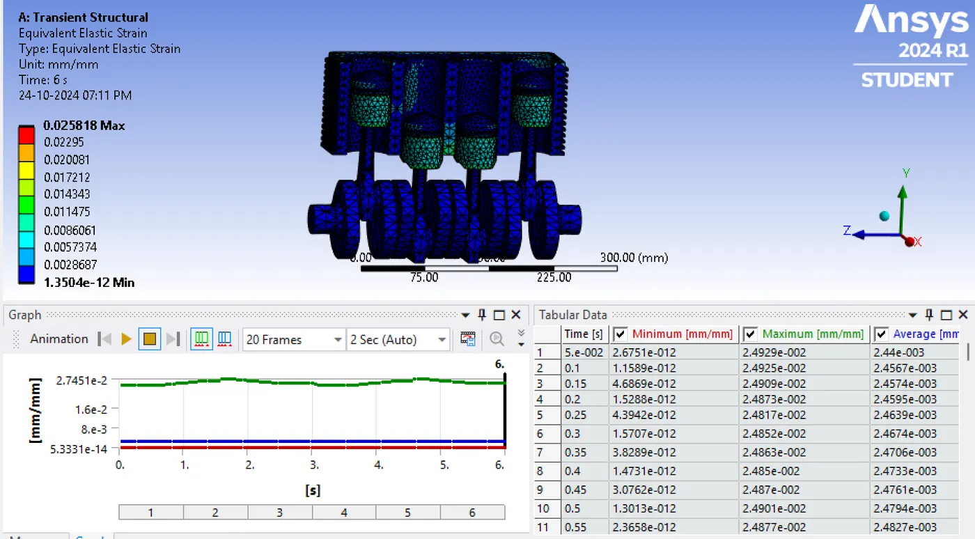
TOTAL DEFORMATION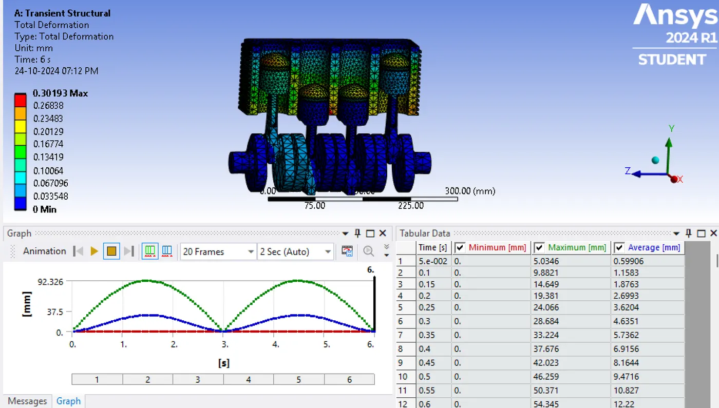
DIRECTIONAL DEFORMATION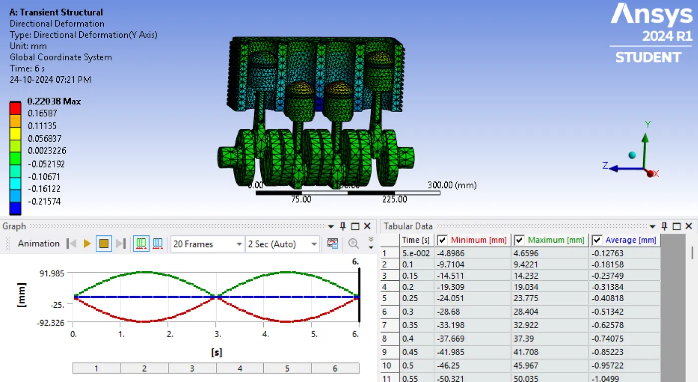
CONCLUSION
The transient structural analysis of a four cylinder engine has been successfully done. The stress, strain and deformation developed on the engine when it is subjected to real life condition has been found out.
The maximum stress, strain and deformation at critical points are identified.
This analysis ensures that the engine does not experience structural failure when subjected to loading condition and this analysis is often used in early stages of engine design to identify potential weak areas. This aids material optimization, suggesting where extra material or reinforcement might be necessary without making engine too heavy.
The maximum stress, strain and deformation at critical points are identified