Independent Research Project
#CFD #ANSYSFLUENT
Topic: A Parametric study and Computational assessment of the MQ-1 Predator (UAV) Aircraft using Ansys Fluent.
AIM: To study and simulate MQ-1 Predator using Ansys.
OBJECTIVE:
- To describe MQ-1 Predator and its importance. simulate three velocities from 100 m/sec to 300 m/sec with the default air properties in fluent.
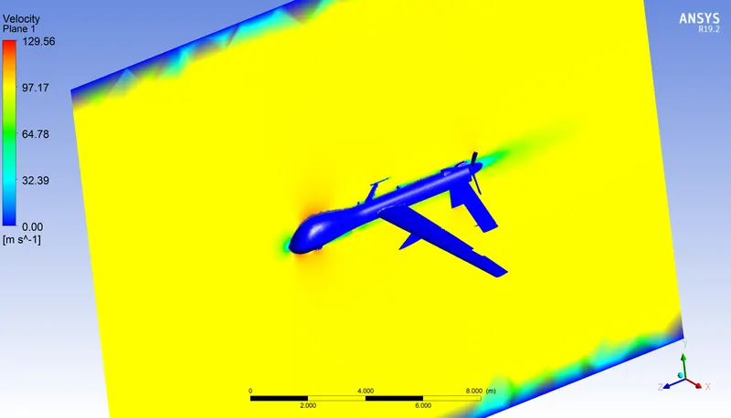
- To calculate the pressure and velocity contours of the whole aircraft model.
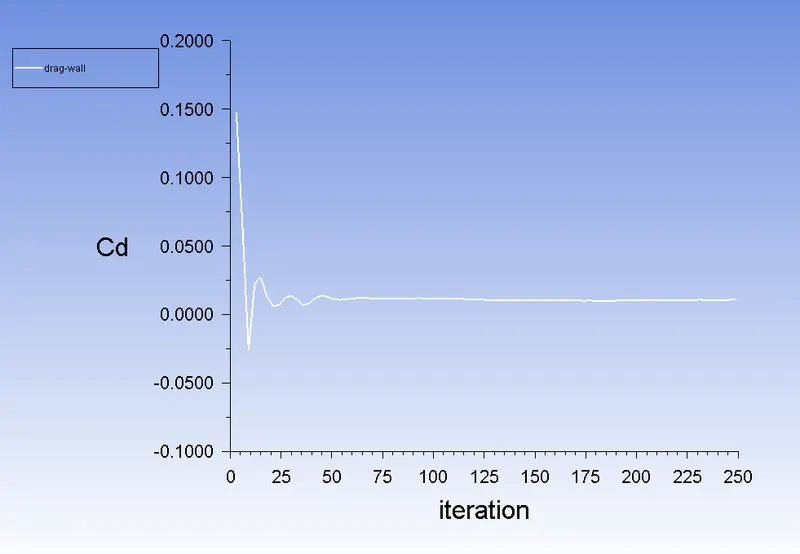
- To calculate and analyse the drag coefficient and drag lift.
- The main objective of this project is to study and analyse the MQ-1 Predator, considering all parameters in real-time.
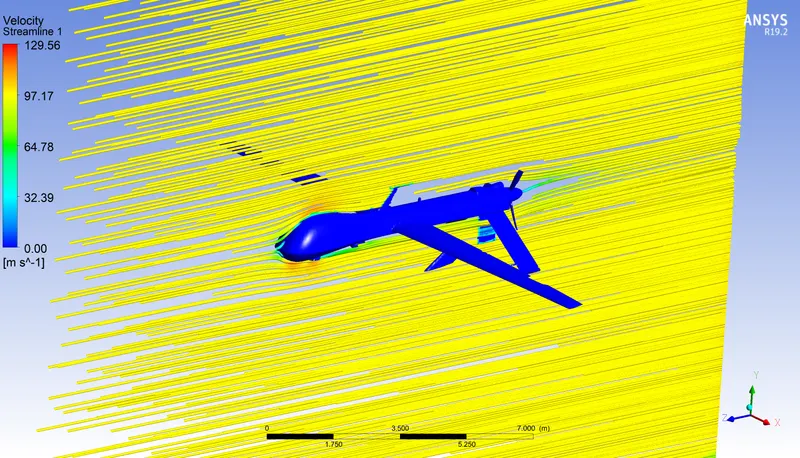
- A pictorial simulation of flow over an aircraft model.
INTRODUCTION:
- The national security of any country is affected by a variety of factors, one of which is the possession of unmanned aerial vehicles (UAVs). They are far superior to manned ones because they can work in boring and predictable, dirty, and dangerous conditions. Such benefits entice anyone in this field to investigate the common ones, particularly the long service-life aircraft. As a distinctive UAV, the MQ-1 Predator was described in 2012 as one of the most accident-prone aircraft in the USA Air Force fleet.
- Various CFD studies have been applied to investigate the behaviour of unmanned aircraft. when using modifications, the aerodynamic characteristics changed as the lift dropped and the drag increased due to these modifications. Also, they stated that choosing suitable locations for external modifications are needed to get better aerodynamic performance. All previous studies have focused on how external modifications affect the aerodynamic performance of the aircraft.
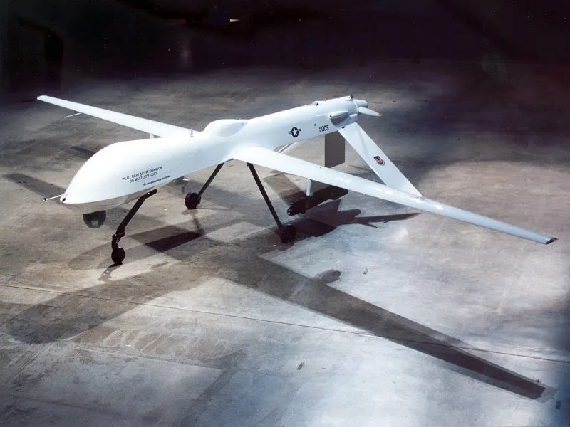
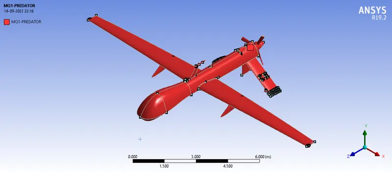
- However, CFD provides an effective alternative and can help to study and analyze the effects of external modifications in an efficient, yet accurate manner. Due to the lack of computational and experimental studies on the MQ-1 Predator, Figure1, the present study focuses on studying the baseline aircraft and then applying modifications by adding slots to the wing and comparing the change in the aerodynamic performance.
Governing Equations:
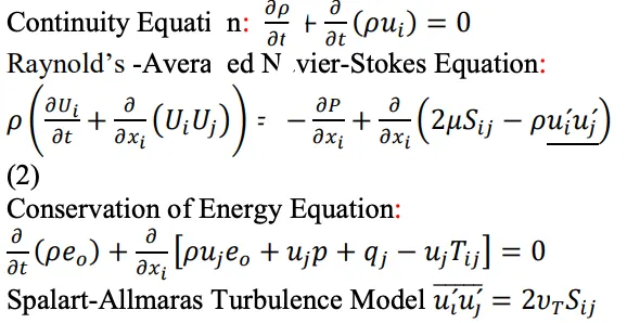
- The simulation is governed by continuity, Navier-Stokes (momentum conservation), and energy equations. For the turbulent flow, the Reynolds-Averaged version of these equations was used. The Spalart-Allmaras turbulence model was used to close the Reynolds-Averaged equation set. The Spalart-Allmaras turbulence model has been developed for aerospace applications that are wall-bounded and subject to adverse pressure gradients.
- The Spalart-Allmaras model has only one equation, which solves the kinematic eddy viscosity. The variables of the problem are solved in all cell centres of the mesh. There are six variables to solve for three components of velocity, pressure, temperature, and kinematic eddy viscosity. The equations are given as follows:
SOLIDWORKS Modeling:
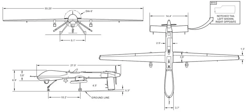
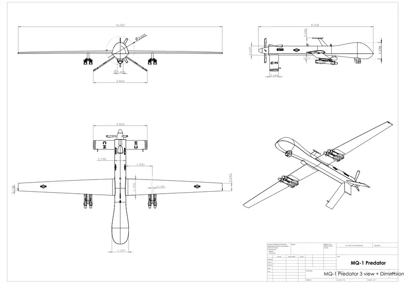
- Without any available geometry provided by the designer of MQ-1 Predator and depending on the drawings shown in the below figure, professionals provided a 3D CAD model of the whole aircraft with full system payload in GrabCAD. Some issues have been faced with this model such as gaps, interferences, zero thickness features, and multiple parts. These problems were fixed, obtaining the shown CAD model. Then, all the models of the case studies and domains were constructed out of this baseline model.
GEOMETRY SETUP:
- The geometry of the MQ-1 Predator is shown below,
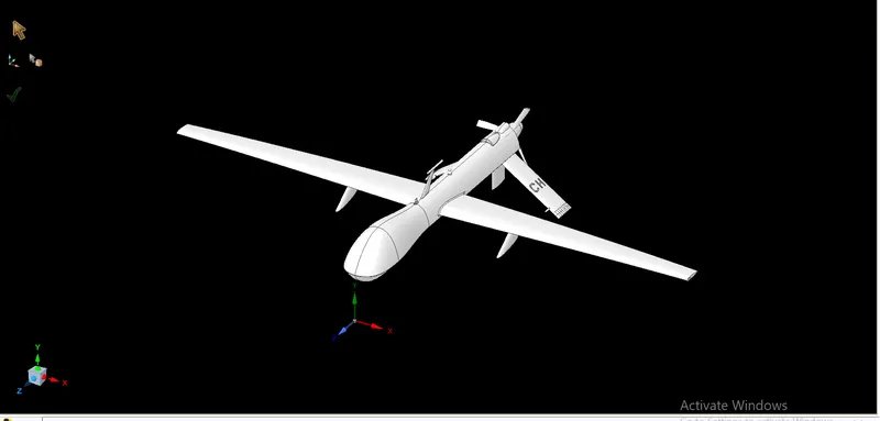
- Load the MQ-1 Predator model into SpaceClaim and convert the units from millimetres to meters.
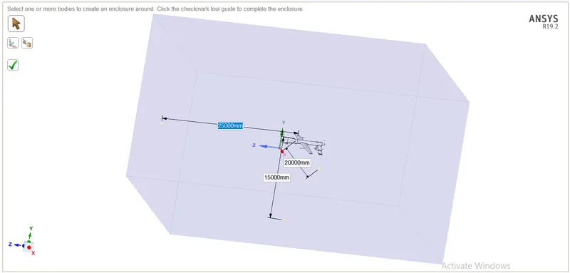
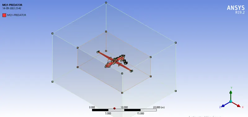
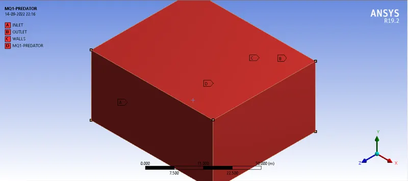
- Creating the rectangular box around the body, As the body is perfectly symmetric, we simulation by considering the only half body. once the enclosure is done, we can create another close enclosure around MQ-1 Predator so that we can refine the mesh in that enclosure and keep the total cell countless.
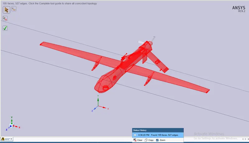
SHARE TOPOLOGY:
MESHING:
- In this meshing we can assign the named selection for Inlet, Outlet, Symmetry wall and Predator Wall, We can use the different types of meshing processes for this model.
-
Meshing will be done for the outer enclosure chosen as a method of the Multizone and this will create the mesh, The element size used for this is 1 m.
- For the inner enclosure we choose the body sizing method to make more refinement, the element size we use for this is 0.5 m.
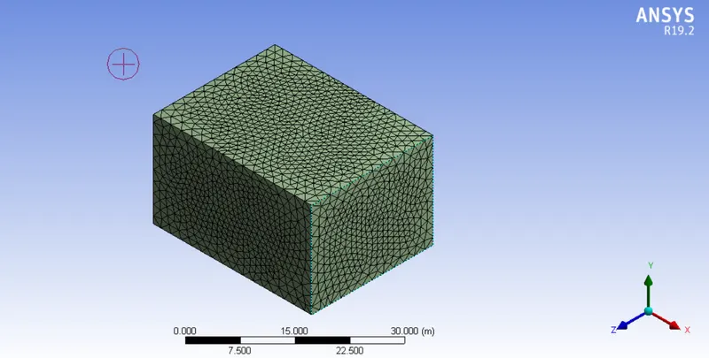
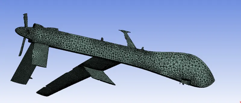
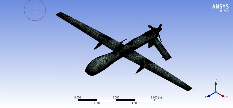
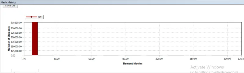

- From the above images, the fine Mesh quality is associated and the total no of nodes and elements is shown above.
NAMING SELECTION:
- The Inlet, outlet and main body are named during meshing.
SIMULATION SETUP:
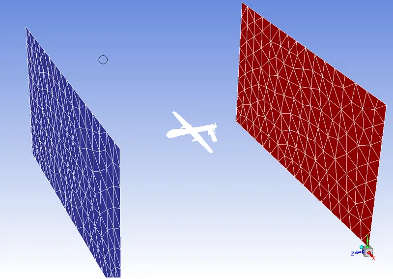
- Importing mesh into the setup.
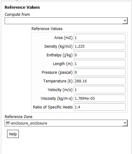
REFERENCE VALUE:
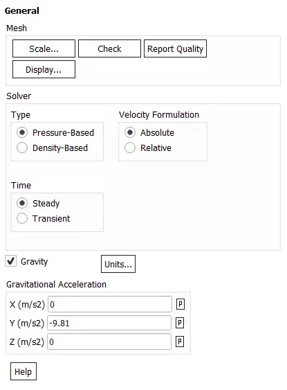
- Solver type: Pressure based
- Check the Energy equation
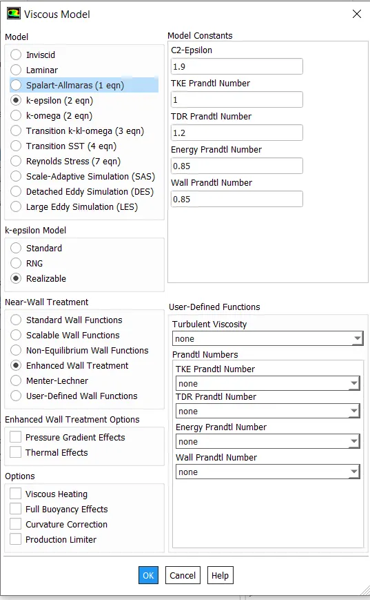
- Turbulent Model: K-Epsilon, Realizable, Enhanced Wall Treatment.
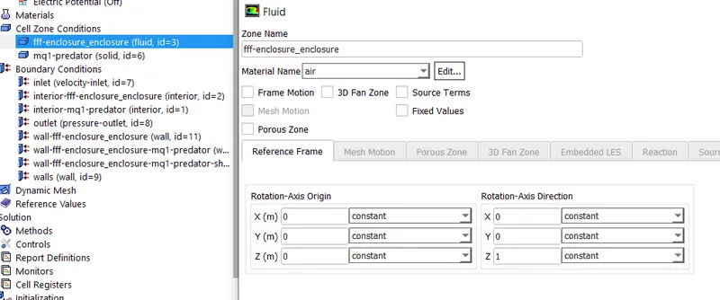
- Fluid Material: Air
- Gravity -9.81 on the Y-axis.
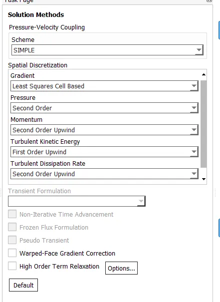
- In the solution method, the second order upwind is selected in Turbulent Dissipation Rate.
Material Selection:
- Air is selected in this simulation.
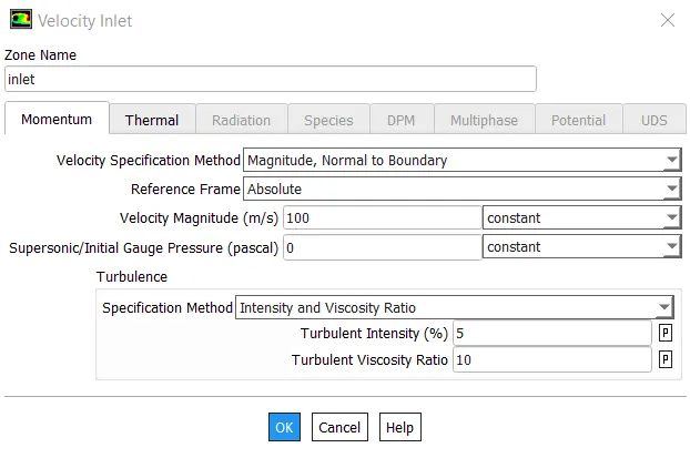
Boundary Condition:
Initialization:
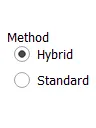
- Here Hybrid initialization is carried out
SOLUTION:
FOR CASE-1:
Inlet velocity : 100 m/s.
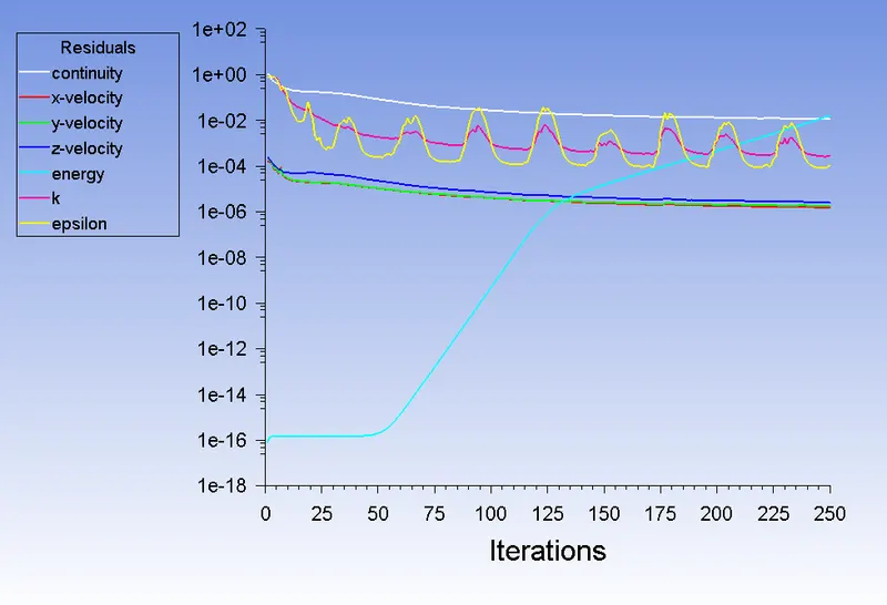
- RESIDUAL PLOT:
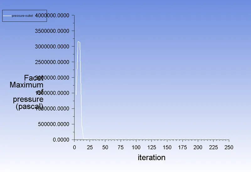
- PRESSURE GRAPH:
- VELOCITY GRAPH:
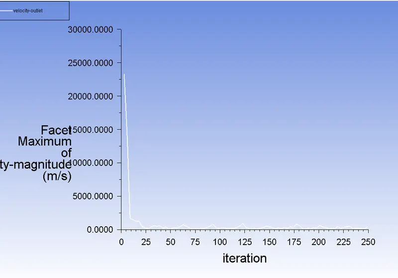
- DRAG WALLS:
- VELOCITY CONTOURS:
- VELOCITY STREAMLINE:
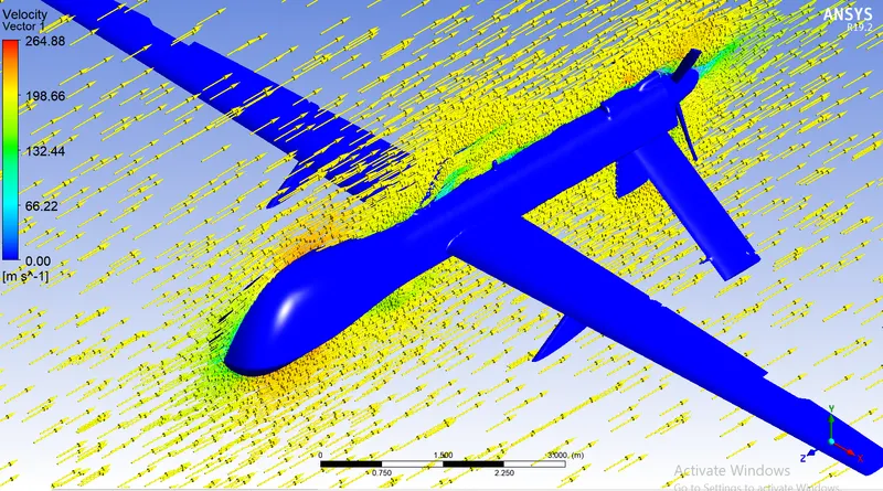
- VELOCITY VECTOR:
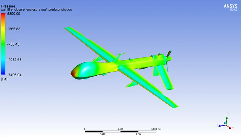
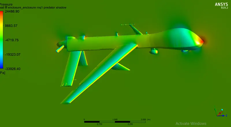
- PRESSURE CONTOURS:
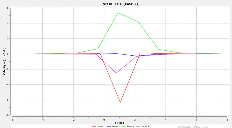
- VELOCITY-U CHART:
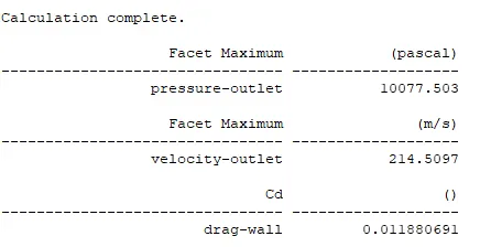
- RESULT FOR CASE -1:
- ANIMATION:
FOR CASE-2:
Inlet velocity : 200 m/s.
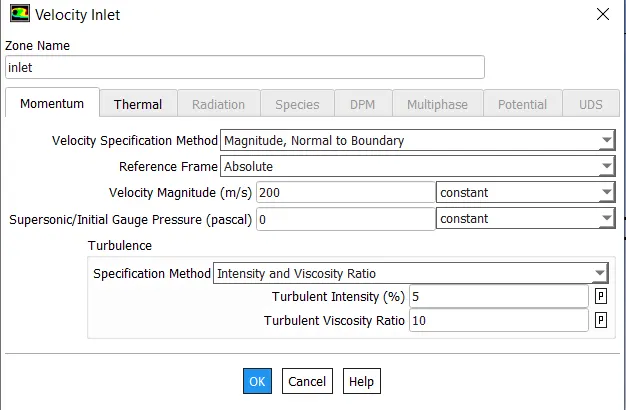
BOUNDARY CONDITIONS:
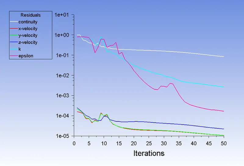
- RESIDUAL PLOT:
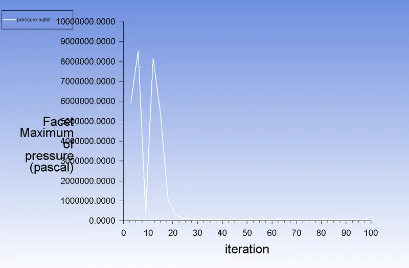
- PRESSURE GRAPH:
- VELOCITY GRAPH:
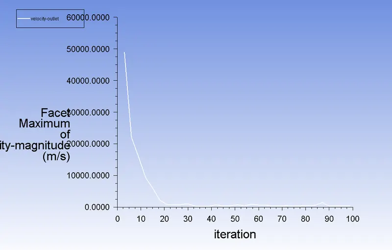
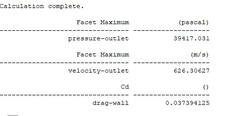
- DRAG WALLS:
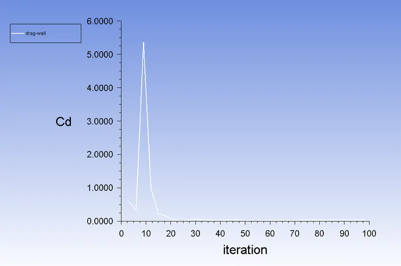
- VELOCITY CONTOURS:
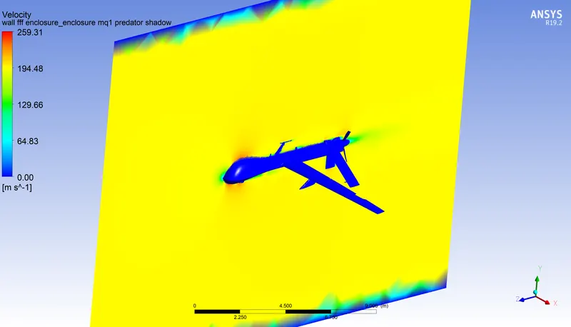
- VELOCITY STREAMLINE:
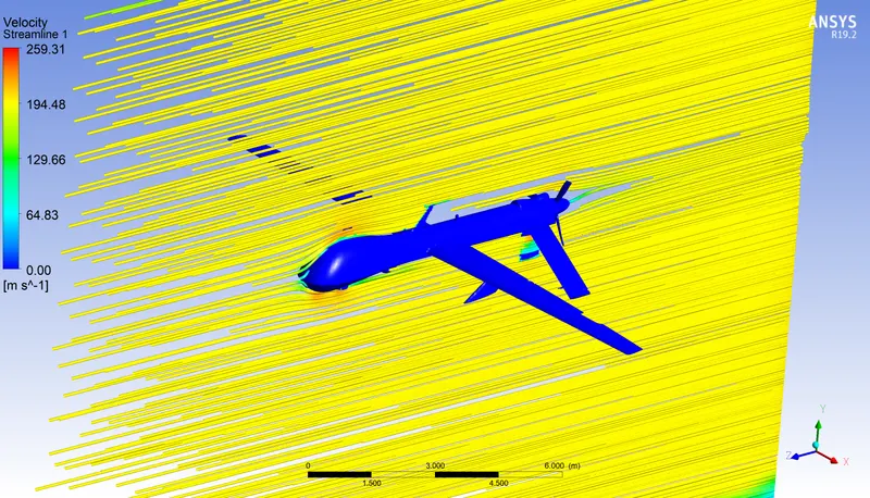
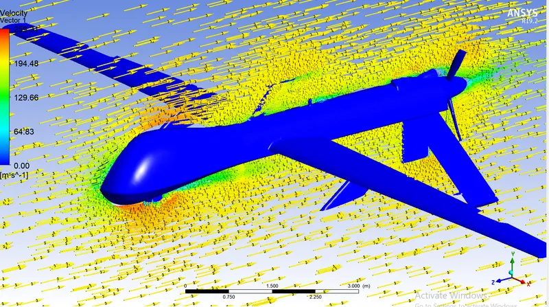
- VELOCITY VECTOR:
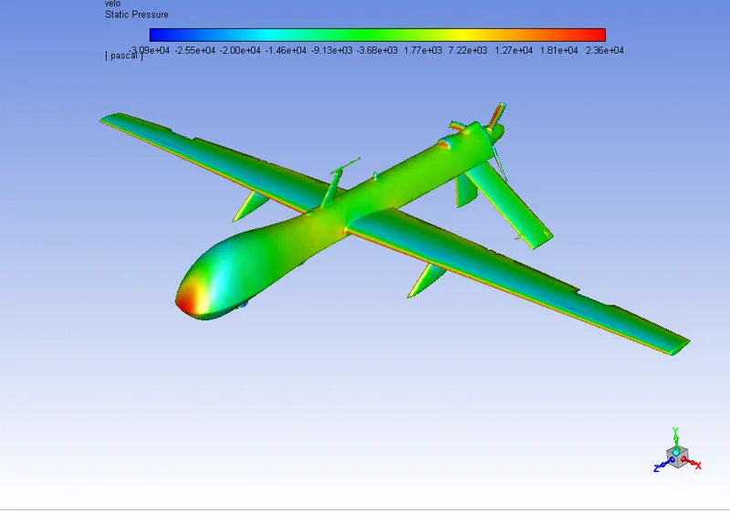
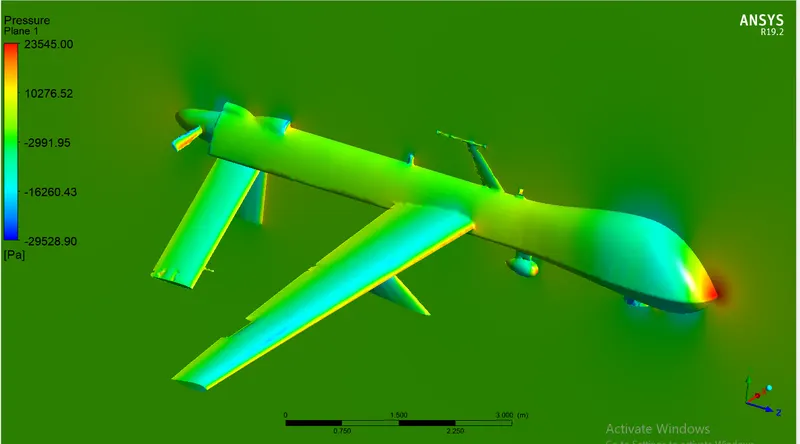
- PRESSURE CONTOURS:
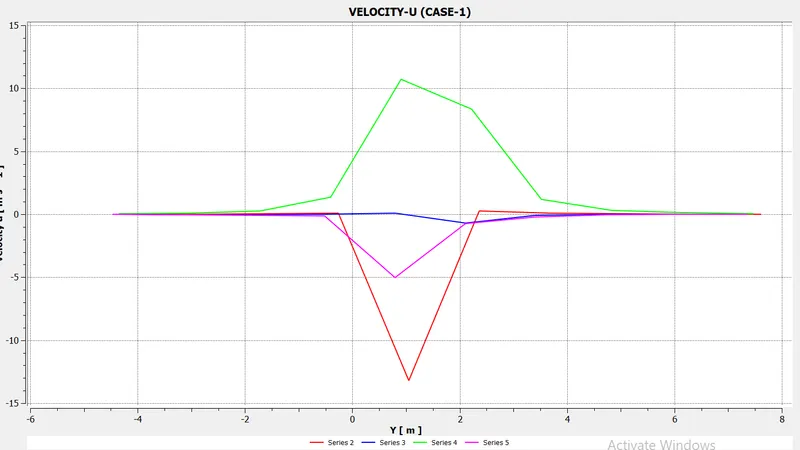
- VELOCITY-U CHART:
- RESULT FOR CASE -2:
- ANIMATION:
FOR CASE-3:
Inlet velocity : 200 m/s.
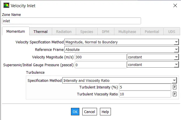
BOUNDARY CONDITIONS:
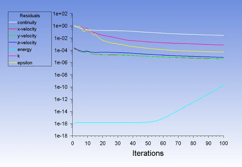
- RESIDUAL PLOT:
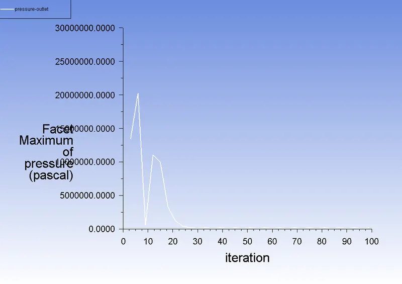
- PRESSURE GRAPH:
- VELOCITY GRAPH:
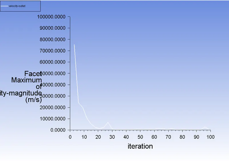
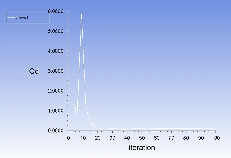
- DRAG WALLS:
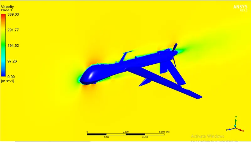
- VELOCITY CONTOURS:
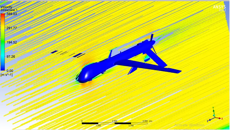
- VELOCITY STREAMLINE:
- VELOCITY VECTOR:
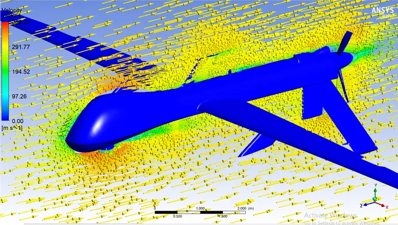
- PRESSURE CONTOURS:
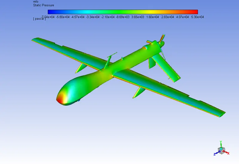
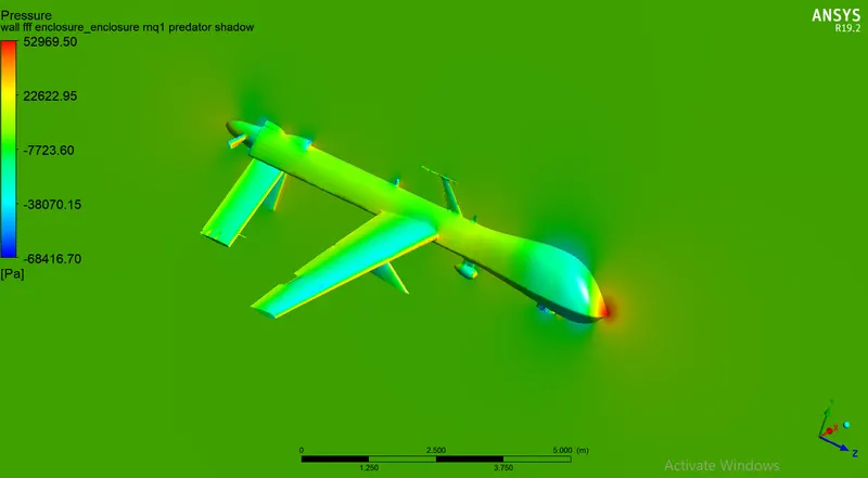
- VELOCITY-U CHART:
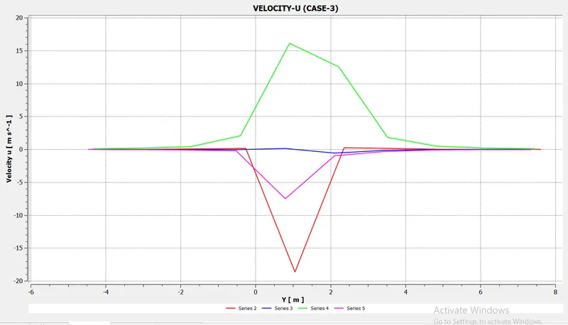
- RESULT FOR CASE -3:
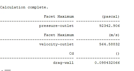
- ANIMATION:
CONCLUSION:
- The AMQ-1 Predator frontal region experiences high pressure because of the air's loss of kinetic energy.
- Because of the flow separation caused by the model's geometry, an adverse pressure gradient is produced close to the wake regions. The pressure gradient changes as a result of flow separation, which in turn changes the drag and lift coefficients.
- Detachment of the fluid should occur farther from the body in order to reduce the size of the wake region, which can be accomplished by increasing the slant angle. The numerical results get closer to the experimental results as the mesh size is increased.
- The AMQ-1 Predator aircraft model shows that the drag coefficient is higher. Due to the full configuration simulation of the aircraft model with the modified wing, the advantage of the modified wing disappeared as a result of flow interaction between the weapon system of the aircraft and the slot of the modified wing.
- The modified design is manufactured using Carbon fibre, laser-cut wooden parts and 3D printed parts for supporting the structure. A simple control system is developed, and the manufactured model will be used for further testing.
REFERENCES: