Independent Research Project
Heat Transfer Analysis of a Shell and Tube Heat Exchanger
Aim:
Design of shell and tube heat exchanger using CFD. To study the temperature inside the tube with different velocity.
Objectives:
- Run the simulation by varying the tube velocity from 1m/s to 5m/s for at least 3 velocities
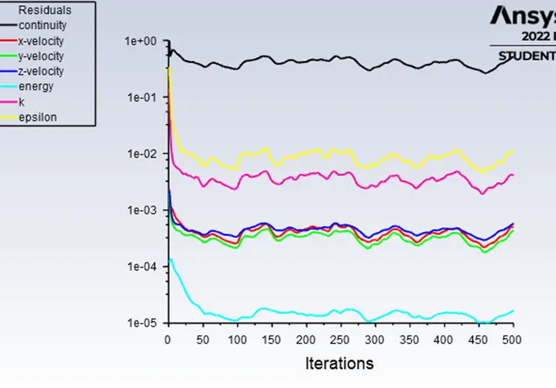
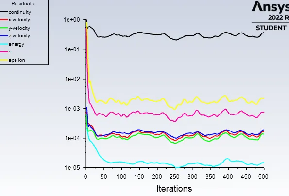
- Prove that the simulation has achieved convergence with appropriate images and plots.
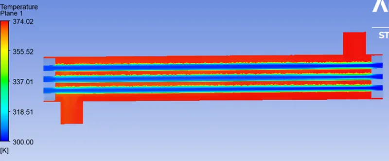
- Find out the maximum temperature of fluids in outlets.
Types of Heat Exchanger
On the basis of nature of heat exchange procedure:
- Direct contact heat exchanger: In this HE, fluids are mixed with each other and heat transfer will take place.
- Indirect contact heat exchanger: In this HE, fluids are separated by a thin wall and heat transfer takes place by convection and conduction.
Indirect contact HE has two types:
(a) Regenerator type: In this HE, hot and cold fluid pass alternately through a space which contains solid matrix. When hot fluid pass through matrix then it heats the matrix and after that cold fluid pass through it then hot matrix transfer heat to the cold fluid.
(b) Recuperator type: It is most useful HE in which two or more fluid pass simultaneously but they are not allowed to be mixed. in this type of HE, heat transfer takes place in both side of dividing wall(pipes or tubes).
On the basis of relative direction of fluid motion:
- i) Parallel flow heat exchanger: In this HE, both fluid flowing in the same direction.
- ii) Counter flow heat exchanger: In this HE, both fluid flowing the opposite direction.
iii) Cross flow heat exchanger: In this HE, one fluid flows at some angle to the other fluid.
Applications of Heat Exchanger
- IC engines and Automobile radiators.
- Open hearth and glass melting furnaces.
- Air heater and blast furnaces.
- Oil coolers, Intercoolers, Air preheaters, Economizers, Super heaters, Condensers, and surface feed heaters of steam power plants.
- Milk chiller and Pasteurizing Plant.
- Evaporator of Ice plant etc.
Shell and Tube Heat Exchanger
For high pressure application, there is a heat exchanger called shell and tube heat exchanger is used. It is an indirect contact type heat exchanger under the subdivision of recuperator. It is a most versatile heat exchanger. By some modification, it can be act as a parallel flow, counter flow and cross flow as well. Shell and tube heat exchanger consists of a shell, tubes and headers. Tubes are generally made of cylindrical shape with circular cross section whereas shell has a wide variety according to the requirement. One fluid flows through the tubes and the other fluid pass through the shell. Heat exchanges between these two fluids are by convection-conduction- convection mode. Shell and tube heat exchanger has high value of log mean temperature difference correction factor.
A simple shell and tube heat exchanger can work as a parallel flow and counter flow heat exchanger but to make it a cross flow heat exchanger, some modification is to be done. Introducing baffles in the shell side is one of the modification
Need of Baffles
Baffles are provided in the shell side.
- To give structural rigidity.
- To prevent vibration.
- To prevent the tubes from sagging.
- To divert the flow of shell side fluid.
- Baffles are used to obtain higher coefficient of heat transfer.
Types of Baffles
There are various types of Baffles used in the industries
- Plate Baffle
- Helical Baffle
- Segmental Baffle
- Ladder type fold Baffle etc.
Spacing between the baffles affecting the heat transfer coefficient and heat transfer rate also. Baffle spacing the distance between two adjacent baffles. Segmental and plate Baffles are provided with cut called baffle cut to passing the fluid. During the fluid flow in shell side, recirculation and eddies are formed near the baffles. Other Baffles are expensive and difficult in manufacturing. Now a day researchers are trying to optimize the segmental baffles for better heat transfer and effectiveness.
Navier-Stokes Equation:
It is named after Claude-Louis Navier and Gabriel Stokes, He described the motion of fluid substances. It’s also a fundamental equation being used by ANSYS and even in the present project work. These equation arise from applying second law of newton to fluid motion, together with the assumption that the fluid stress is sum of a diffusing viscous term, plus a pressure term. The derivation of the Navier Stokes equation begins with an application of second law of newton i.e conservation of momentum. In an inertial frame of reference,
the general form of the equations of fluid motion is :-
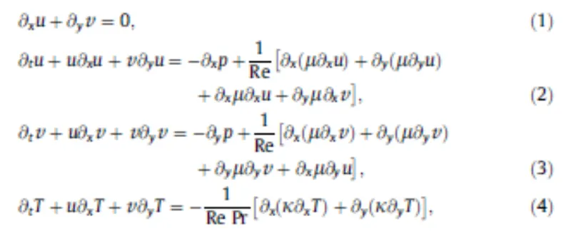
This Navier Stokes Equation solve in every mess shell and the simulation shows the result.
Procedure:
Geometry:
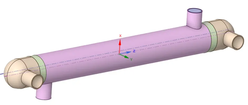
Geometry
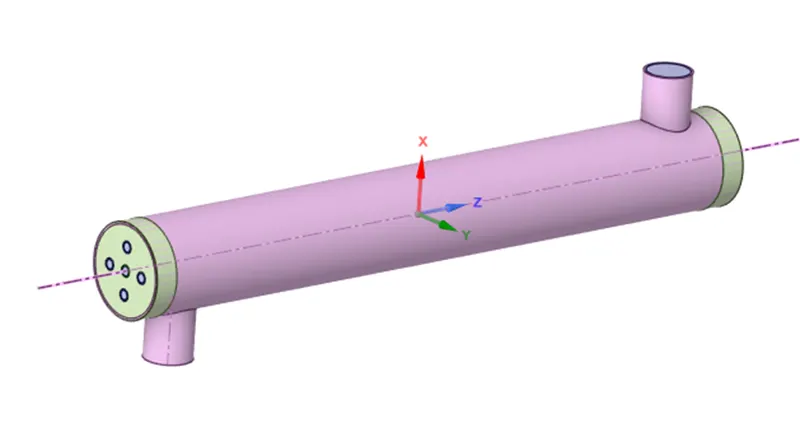
Solids and fluid domains
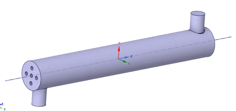
Shell fluid domain
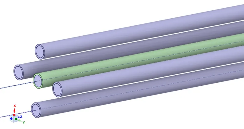
Tube fluid domain
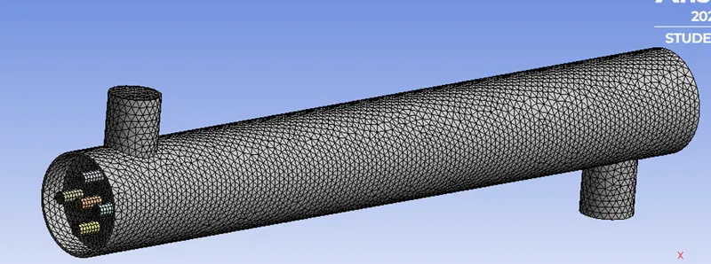
Meshing:
Initially a relatively coarser mesh is generated with 1.8 Million cells. This mesh contains mixed cells (Tetra and Hexahedral cells) having both triangular and quadrilateral faces at the boundaries. Care is taken to use structured cells (Hexahedral) as much as possible, for this reason the geometry is divided into several parts for using automatic methods available in the ANSYS meshing client. It is meant to reduce numerical diffusion as much as possible by structuring the mesh in a well manner, particularly near the wall region. Later on, for the mesh independent model, a fine mesh is generated with 4.982 Million cells. For this fine mesh, the edges and regions of high temperature and pressure gradients are finely meshed.
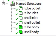
Name selection:
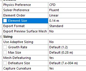
Total number of mesh elements and size:

Case setup:
- In the Fluent solver Pressure Based type was selected, absolute velocity formation and steady time was selected for the simulation.
- In the model option energy calculation was on and the viscous was set as standard k-e, standard wall function (k-epsilon 2 eqn).
- In cell zone fluid Air was selected. Aluminum was selected as materials for both domains.
- Boundary condition was selected for both inlet, shell inlet 1 kg/s velocity and temperature was set at 373k.Across each tube 3 kg/s velocity and 300k temperature was set.
Solution initialization:
Pressure Velocity coupling selected as COUPLED. Skewness correction was set at zero.
In Spatial Discretization zone Gradient was set as least square cell based, Pressure was standard, Momentum was Second order Upwind, Turbulent Kinetic energy was set as First order Upwind, and Energy was set as Second order upwind.
In Solution control, Pressure was 0.7, Density 1, Body force 1, Momentum 0.2, turbulent kinetic and turbulent dissipation rate was set at 1, energy and turbulent Viscosity was 1.
Solution initialization was standard method and solution was initialize from inlet with 300k temperature.
Under the Above boundary condition and solution initialize condition simulation was set for 1000 iteration.
Results:
Case 1:
Shell inlet velocity = 1 m/s.
Tube inlet velocity = 2 m/s.
Residuals:
Temperature plane:
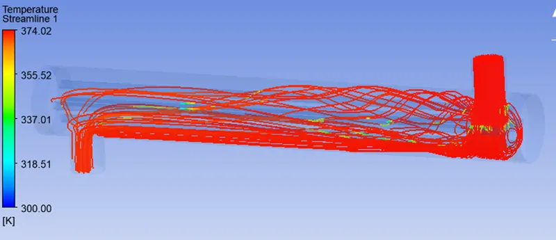
Temperature streamline:
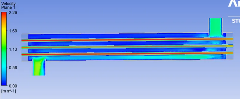
Velocity plane
Velocity streamline:
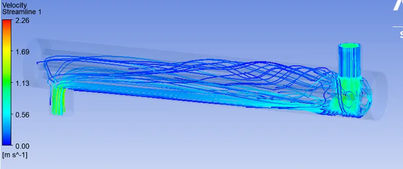
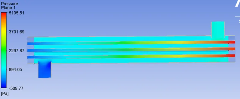
Pressure plane:
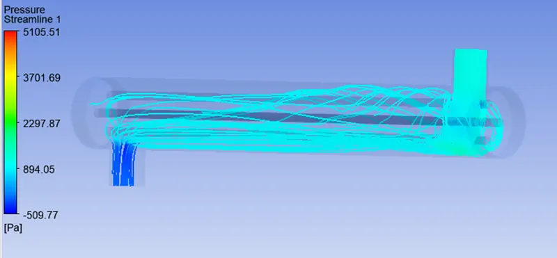
Pressure streamline:
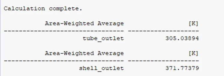
Temperature outlet temperature of heat exchanger:
Mass flow rate shell inlet and outlet:
Shell inlet = 0.249849 kg/s-1
Shell outlet = -0.248839 kg/s-1
Mass flow rate tube inlet and outlet:
Tube inlet = 0.117345 kg/s-1
Tube outlet = -0.117345 kg/s-1
Case 2:
Shell inlet velocity = 1 m/s.
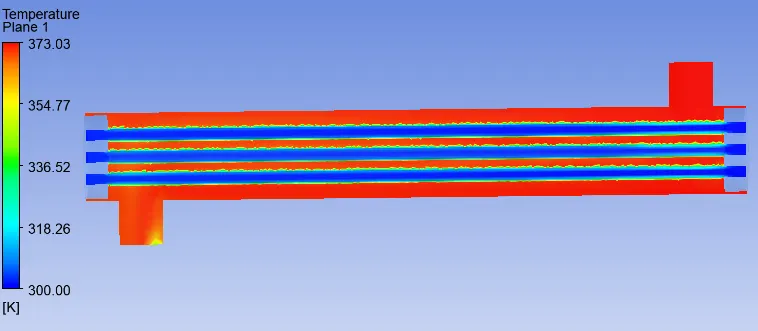
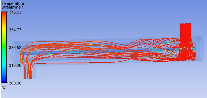
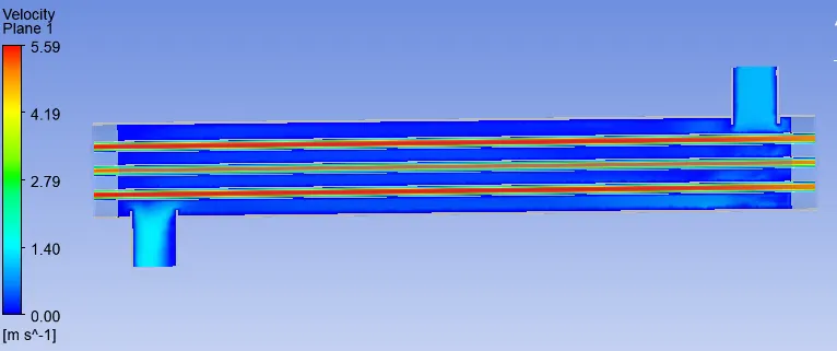
Tube inlet velocity = 3 m/s.
Residuals:
Temperature plane:
Temperature streamline:
Velocity plane:
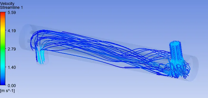
Velocity streamline:
Temperature results:
Shell outlet = 370.37 K.
Tube outlet = 303.69 K.
Case 3:
Shell inlet velocity = 1 m/s.
Tube inlet velocity = 5 m/s.
Residuals:
Temperature plane:
Temperature stream line:
Velocity plane:
Velocity streamline:
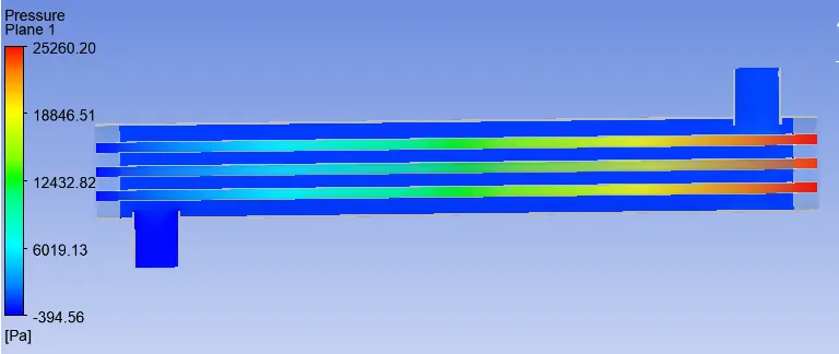
Pressure plane:
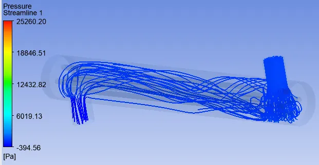
Pressure streamline:
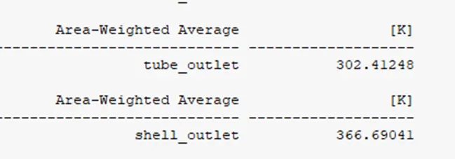
Temperature results:
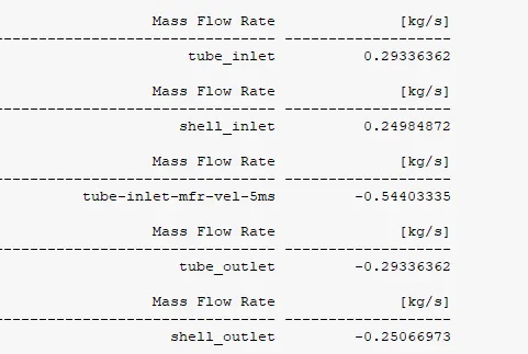
Mass Flow Rate results:
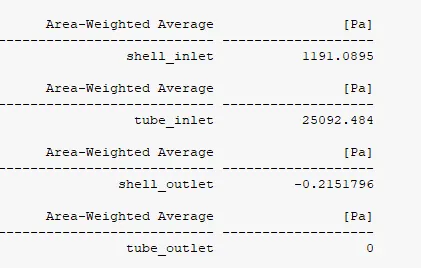
Pressure results:
Conclusions:
The model predicts the heat transfer and pressure drop with an average error of 20%. Thus the model can be improved. The assumption worked well in this geometry and meshing expect the outlet and inlet region where rapid mixing and change in flow direction takes place. it will help in more turbulence across shell side and the heat transfer rate will increase. If different flow rate is taken, it might be help to get better heat transfer and to get better temperature difference between inlet and outlet. Moreover the model has provided the reliable results by considering the standard k-e and standard wall function model, but this model over predicts the turbulence in regions with large normal strain. Thus this model can also be improved by using Nusselt number and Reynolds stress model, but with higher computational theory. Furthermore the enhance wall function are not use in this project, but they can be very useful. Thus the design can further be improved by creating cross-flow regions in such a way that flow doesn’t remain parallel to the tubes. It will allow the outer shell fluid to have contact with the inner shell fluid, thus heat transfer rate will increase.
References:
- Diaper, A.D. and Hesler, L.E., (1990), "Crossflow Pressure Drop and Flow Distributions within a Tube Bundle Using Computational Fluid Dynamic", Proc. 9th Proc. 9th Heat Transfer Conf., Israel, pp. 235-240.
- Jian-Fei Zhang, Ya-Ling He, Wen-Quan Tao , “ 3d numerical simulation of shell and tube heat exchanger with middle-overlapped helical baffle”, a journal ,School of energy and power engineering,china.
- Li, H., Kottke, “Effect of baffle spacing on pressure drop and local heat transfer in shell and tube heat exchangers for staggered tube arrangement”, source book on Int. J. Heat Mass Transfer 41 (1998), 10, pp. 1303–1311.
- Thirumarimurugan, M., Kannadasan, T., Ramasamy, E., Performance Analysis of Shell and Tube Heat Exchanger Using Miscible System, American Journal of Applied Sciences 5 (2008), pp. 548-552.